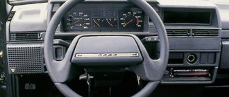
Vehicle controls
The placement of controls is shown in Fig. 1-4.
- 1 – sound signal switch.
- 2 – device composition panel.
- 3 – control wheel.
On a car with a steering wheel with a built-in safety pad, to turn on the sound signals, press the steering wheel trim in the area marked with the appropriate emblem.
- 4 – shield fastening screw.
- 5 – external lighting switch.
When you press the shoulder button to the first fixed position, the side lights turn on, and to the second fixed position, additional headlights. At the same time, the lamp in the switch illuminates the button.
- 6 – heater electric fan switch.
When you press the shoulder of the key to the first fixed position, the low speed of the electric fan is turned on, and to the second fixed position - the highest speed. When the external lighting is turned on, the key illumination lamp lights up.
- 7 – windshield blower nozzles.
- 8 – central nozzles of the interior ventilation and heating system.
- 9 – control unit for the interior ventilation and heating system.
- 10 – rear window heating switch.
The heated rear window is turned on by pressing the button on the shoulder. When the external lighting is turned on, the key illumination lamp lights up.
- 11 – plug.
- 12 – switch for rear fog lights.
The fog lights turn on when the headlights are on in conditions of limited visibility (fog, snow, rain) by pressing the shoulder button. When the external lighting is turned on, the key illumination lamp lights up.
- 13 – glove box.
- 14 – nozzles for blowing glass of front doors.
- 15 – shelf for a first aid kit, magazines and newspapers.
- 16 – plug.
- 17 – plug.
- 18 – socket for installing radio equipment.
The car is equipped with the installation of radio equipment, corresponding in size to international standards (ISO 7736, DIN 7736), with its positive wire connected to the INT terminal of the ignition switch. With all this, you should keep in mind that the current consumption should not exceed 10 A, and a fuse of the appropriate rating is needed in the power supply circuit of the radio device.
- 19 – gear shift lever.
- 20 – gear shift lever in the transfer case.
- 21 – ashtray.
- 22 – key for fixing the parking brake lever.
- 23 – parking brake lever.
By moving the lever upward, the brake pads of the rear wheels are activated. To return the lever to its initial position, press key 22 and lower the lever.
- 24 – cigarette lighter.
To use, press the chuck key to a fixed position. After approximately 15 seconds, the cartridge will automatically return to its initial position, ready for use. When the device lighting is turned on, the lamp illuminates the cigarette lighter socket.
- 25 – differential lock lever in the transfer case.
- 26 – rear window cleaner and washer switch.
When you press the shoulder of the key to the first fixed position, the windshield wiper is turned on, and to the second non-fixed position, the washer is additionally turned on.
- 27 – switch lever for wipers and washers of the windshield and headlights.
- 28 – gas pedal.
- 29 – control lamp for closing the carburetor air damper.
Lights up orange when the ignition is turned on and handle 30 is pulled out.
- 30 – handle for closing the carburetor air damper.
Serves to start a cool engine. When the handle is pulled out one hundred percent, the carburetor air damper is closed; when it is recessed, it is open.
- 31 – alarm switch.
When you press the button, the blinking light of the direction indicators and the warning lamp in the button itself turns on. The alarm goes off when the key is pressed again.
- 32 – brake pedal.
- 33 – ignition switch.
- 34 – clutch pedal.
- 35 – direction indicator switch lever.
- 36 – fuse blocks.
- 37 – hood lock drive lever.
- 38 – device lighting regulator.
Rotating the knob adjusts the brightness of the device lighting and the illumination of signs if the external lighting is turned on.
- 39 – headlight hydraulic corrector.
By rotating the knob, depending on the load of the vehicle, the angle of the headlight beam is adjusted so that oncoming drivers are not dazzled.
The position of the handle in the order of increasing diameters of the circles on the hydraulic corrector scale means:
- one driver;
- all seats are occupied or all seats are occupied plus cargo in the luggage compartment up to the permissible overload on the rear axle;
- one driver plus cargo in the luggage compartment up to the permissible overload on the rear axle.
For other loading options, without exceeding the useful weight, the middle position of the handle is selected.
- 40 – headlight switch lever.
- 41 – composition of devices.
Source: www.vazbook.ru
Controls and dashboard layout
Note The page presents two options for the layout of controls
Option from 2022 release
1 – nozzles of the interior ventilation and heating system. 2 – control wheel. 3 – sound signal switch. 4 – composition of devices. 5 – switch lever for windshield wipers and washers. 6 – rear window wiper switch. 7 – rear window washer switch. 8 – rear window heating switch with indicator light. 9 – air conditioner switch with light indicator (in a variant). 10 – recirculation mode switch with indicator light (in a variant). 11 – glove box cover. 12 – glove box handle. 13 – heating and ventilation unit control unit. 14 – alarm switch. When you press the button, the blinking light of the direction indicators and warning lamp in the device composition is turned on. The alarm goes off when the key is pressed again. 15 – socket for installing radio equipment. (Installation of radio equipment must be carried out only at a LADA dealer with a permanent mark in the service book). 16 – cup holders. 17 – switch for electric heating of the front passenger seat (in a variant). The heating is turned on only when the engine is running. 18 – switch for electric heating of the driver’s seat (in a variant). The heating is turned on only when the engine is running. 19 – gear shift lever. 20 – gear shift lever in the transfer case. 21 – control unit for electric drive of external mirrors and electric windows of front doors (in a variant). 22 – differential lock lever in the transfer case. 23 – sockets for connecting additional electrical equipment. (Used to connect only 12-volt electronic devices with a power of no more than 120 W with a maximum current of 10 A. Electromagnetic compatibility characteristics must comply with DIN VDE 40839.) 24 – gas pedal. 25 – brake pedal. 26 – clutch pedal. 27 – ignition switch. 28 – headlight hydraulic corrector. (By rotating the knob, depending on the load of the vehicle, the angle of the headlight beam is adjusted so that oncoming drivers are not dazzled). 29 – direction indicator switch lever. 30 – headlight switch lever. 31 – lighting control module.
Option until 2022 release
Rice. 13. Controls
The placement of controls is shown in Fig. 13.
1 – horn switch . 2 – device composition panel . 3 – control wheel . 4 – shield fastening screw. 5 – external lighting switch . When you press the shoulder button to the first fixed position, the side lights turn on, and to the second fixed position, additional headlights. At the same time, the lamp in the switch illuminates the button. 6 – heater electric fan switch. When you press the shoulder of the key to the first fixed position, the low speed of the electric fan is turned on, and to the second fixed position - the highest speed. When the external lighting is turned on, the key illumination lamp lights up. 7 – windshield blower nozzles . 8 – central nozzles of the interior ventilation and heating system . 9 – control unit for the interior ventilation and heating system. 10 – rear window heating switch . The heated rear window is turned on by pressing the button on the shoulder. When the external lighting is turned on, the key illumination lamp lights up. 11 – block of indicator lamps for turning on the heated rear window and turning on the differential lock . 12 – plug . 13 – glove box. 14 – nozzles for blowing glass of front doors. 15 – shelf for a first aid kit, magazines and newspapers. 16 – plug . 17 – rear fog light switch . The fog lights turn on when the headlights are on in conditions of limited visibility (fog, snow, rain) by pressing the shoulder button. When the external lighting is turned on, the key illumination lamp lights up. 18 – socket for installing radio equipment . The installation of radio equipment must be carried out only on a certified PSSS with an indispensable mark in the service book.
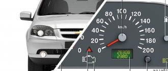
Niva instrument panel: description of indicator lamps
| Number | Description |
| 3/4 | The turn indicators turn on simultaneously when the hazard warning lights are activated. |
| 7 | Insufficient fuel level in the gas tank. |
| 8 | The vehicle's side lighting is on. |
| 9 | Emergency situation in the brake system. |
| 10 | The long-range illumination of the head optics is activated. |
| 12 | Vehicle mileage monitor. |
| 13 | Check engine light. If the indicator lights up, you need to carefully check the power plant. |
| 14 | Hazard warning light. |
| 15 | Clock display. |
| 16 | If the lamp lights up, you need to check the generator and battery charging. |
| 17 | Handbrake activated |
| 18 | The engine oil level has dropped critically. |
| 19 | Most configurations include a backup lamp. |
You should also highlight the colors of the car's indicators. They can be divided into three parts.
- Green/blue – indicators of these colors indicate normal operation of machine components.
- Orange/yellow - tells the driver that a certain unit requires attention or service.
- Red is the most dangerous color. If a lamp of this color lights up on the dashboard, the car must be urgently shown to a mechanic.
Exclamation mark on the Niva panel
Indicates that the fluid level in the brake system has decreased. You will need to open the expansion tank cap and add brake fluid to the required level. It is recommended to check the line for leaks and pad wear.
Controls of VAZ 21214
External lighting switch When you press the lower arm of the key, the side lights are turned on before the first fixed position, and the headlight circuits are additionally energized before the second fixed position. At the same time, a special lamp in the switch illuminates the button.
Heater fan switch Is energized when the ignition is on. When you press the lower arm of the key, the low speed of the electric fan is turned on to the first fixed position, and the highest speed is turned on to the second fixed position. At the same time, a special lamp in the switch illuminates the button.
Rear window heating switch Is energized when the ignition is on. The heated rear window is turned on by pressing the lower arm of the button. If the device lighting is turned on, an orange lamp illuminates the switch button.
Rear fog light switch Is energized when the headlights are on. The fog lights are turned on in conditions of limited visibility (fog, snow, rain) by pressing the lower arm of the key.
Parking brake lever Moving the lever upward activates the brake pads on the rear wheels. To return the lever to its initial position, press key 22 and lower the lever.
Cigarette lighter To use, press the key to the fixed position. After approximately 15 seconds, the cartridge will automatically return to its initial position, ready for use. When the device lighting is turned on, a special lamp illuminates the cigarette lighter socket.
Rear window wiper and washer switch Is energized when the ignition is on. When you press the lower arm of the key to the first fixed position, the windshield wiper is turned on, and to the second non-fixed position, the washer is additionally turned on.
The indicator lamp for closing the carburetor air damper lights up in orange when the ignition is turned on when handle 30 is pulled out.
Hazard warning switch When you press the button, the blinking light of the direction indicators and the warning lamp in the button itself turns on. The alarm goes off when the key is pressed again.
Device lighting control Rotate the knob to adjust the brightness of device lighting if the external lighting is turned on.
Hydrocorrector of headlights Rotating the knob, depending on the load of the vehicle, adjusts the angle of the light beam so that drivers of oncoming traffic are not dazzled by low-beam headlights. The position of the handle in the order of increasing diameters of the circles on the hydraulic corrector scale means: – one driver; – all seats are occupied; – all seats are occupied plus cargo in the luggage compartment up to the permissible overload on the rear axle; – one driver plus cargo up to the permissible overload on the rear axle.
For other loading options, without exceeding the useful weight, the middle position of the handle is selected.
Source: zinref.ru
Niva: tidy does not work
There are several ways to solve the problem.
- On the version with a carburetor, check the fuse and the device itself. Turn signals and other vehicle devices can work.
- If the car does not start, the malfunction probably occurred on the injection machine. Here you will need to perform computer diagnostics.
The Niva's tidy was constantly changing and updating. The board, regardless of modification, is informative and easy to perceive.
Specialization : Graduated from the State Automobile University, worked for 20 years at GAZ-56, now I drive a Zhiguli.
Source
VAZ-2131. Controls
Rice. 13. Controls
The placement of controls is shown in Fig. 13.
1 – sound signal switch. 2 – device composition panel. 3 – control wheel. 4 – shield fastening screw. 5 – external lighting switch. When you press the shoulder button to the first fixed position, the side lights turn on, and to the second fixed position, additional headlights. At the same time, the lamp in the switch illuminates the button. 6 – heater electric fan switch. When you press the shoulder of the key to the first fixed position, the low speed of the electric fan is turned on, and to the second fixed position - the highest speed. When the external lighting is turned on, the key illumination lamp lights up. 7 – windshield blower nozzles. 8 – central nozzles of the interior ventilation and heating system. 9 – control unit for the interior ventilation and heating system. 10 – rear window heating switch. The heated rear window is turned on by pressing the button on the shoulder. When the external lighting is turned on, the key illumination lamp lights up. 11 – block of indicator lamps for turning on the heated rear window Ш] and turning on the differential lock 1-Ф1. 12 – plug. 13 – glove box. 14 – nozzles for blowing glass of front doors. 15 – shelf for a first aid kit, magazines and newspapers. 16 – plug. 17 – switch for rear fog lights. The fog lights turn on when the headlights are on in conditions of limited visibility (fog, snow, rain) by pressing the shoulder button. When the external lighting is turned on, the key illumination lamp lights up. 18 – socket for installing radio equipment. The installation of radio equipment must be carried out only on a certified PSSS with an indispensable mark in the service book.
Body and interior of Niva Chevrolet …………………….4
- Car keys……………………..4
- Remote control system….5
- Chevrolet Niva instructions for replacing the battery of the key with remote control………………………..8
- Doors……………………………………………………………9
- Seats………………………………………………………11
- Adjusting the steering wheel position……………………12
- Seat belts………………………..13
- Airbags…………………14
- Safety of infants and small children …………………………..17
- Installing a child seat……………18
- Interior equipment Chevrolet Niva operating manual……………19
- Hood…………………………………………………………..21
- Fuel tank cap………………….21
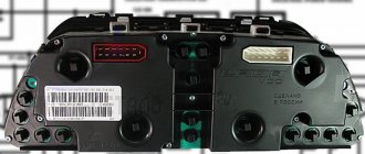
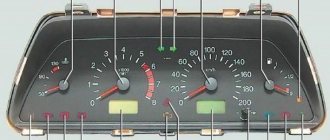
VAZ-2131. Device panel
ATTENTION! Do not allow the engine to operate in the reddish zone, or the engine to operate at a frequency of less than 800 min-1 when starting and driving.
Rice. 14. Composition of devices
3 – control lamp for turning on the direction indicators on the left side. Lights up with a greenish flashing light when the left turn is turned on. 4 – control lamp for turning on the direction indicators on the right side. Lights up with a greenish blinking light when the right turn is turned on. 5 – speedometer. 6 – fuel level indicator. 7 – fuel reserve warning lamp. Lights up orange if there are at least 4 - 6.5 liters left in the fuel tank.
8 – control lamp for turning on the side light. Lights up green when external lighting is turned on. 9 – warning lamp for emergency condition of the working brake system. Lights up reddish when the water level in the brake hydraulic reservoir drops below the “MIN” mark. ATTENTION! When the warning light comes on, movement is prohibited until the circumstances surrounding the drop in water level are eliminated. 10 – indicator lamp for turning on high beam headlights. Lights up blue when the headlights are on high beam. 11 – reset key. 12 – mileage indicator. The top line of the indicator indicates the total mileage of the vehicle, and the bottom line is the daily counter of the distance traveled. Reset the day counter readings by holding key 11 pressed for more than 5 seconds when the vehicle is stopped. Resetting the day counter to zero also occurs when the terminal is removed from the battery. 13 – “check engine” warning lamp. The lamp lights up when the ignition is turned on and goes out after the engine starts, if there are no malfunctions in the engine control system. If any deficiency is detected in the system, the lamp glows constantly or flashes. 14 – warning lamp for turning on the hazard warning lights. Lights up with a reddish flashing light when the hazard warning lights are turned on. 15 – indicator of clock, temperature and voltage of the on-board network. Switching between the time display, ambient temperature display and on-board power supply voltage display is carried out by briefly pressing key 11. When the ignition is turned on at an ambient temperature above +20C, the clock display constantly appears. When the ambient temperature drops below +20C, the indicator displays the clock readings for 3 s, and then switches to the temperature display, which is displayed in a flashing mode for the first 10 s. When the outside air temperature rises above +30C and drops again to +20C: – in the case of a clock indication, the indicator automatically switches to a temperature indication, the readings of which are displayed in a flashing mode for the first 10 s; – in the case of temperature indication, its normal mode is interrupted by a ten-second flashing mode. Setting the hours and minutes is done in the time display mode by rotating key 11 towards the symbols “h” - hours and “mo-minutes”. After removing the terminal from the battery and the next restoration of voltage, the time is counted from zero. 16 – battery charge indicator lamp. Lights up with a reddish light when the ignition is turned on and goes out after the engine is started. The colorful lighting of the lamp or its glow at full intensity while the engine is running indicates a weak tension (break) in the generator drive belt or a malfunction in the charging circuit, or perhaps the generator itself. 17 - indicator lamp for turning on the parking brake. Lights up reddish when the parking brake is applied. 18 – indicator lamp for insufficient oil pressure. Lights up with a reddish light when the ignition is turned on and goes out after the engine is started. When the engine is running, it lights up with a reddish light if the pressure in the engine lubrication system is insufficient. 19 – reserve.
ATTENTION! Never allow fuel to run out completely. This increases wear on the fuel system components and can lead to an emergency on the road due to an unexpected stop of your car, as well as overheating and damage to the converter.
ATTENTION! If the emergency oil pressure warning light comes on, immediately stop driving, turn off the engine and contact a certified service center to troubleshoot the problem, because Insufficient pressure in the lubrication system will lead to serious damage to the engine.
Source: sinref.ru
Maintenance and current repair of a car Manual Niva Chevrolet ………………………….51
- Engine lubrication system………………52
- Engine cooling system………53
- Brake system………………………….54
- Hydraulic clutch release ..55
- Power steering ..56
- Battery …………………57
- Washer fluid…………………….58
- Spark plugs……………………………58
- Caring for Chevrolet Niva tires Manual………………..59
- Replacing wheels……………………………………61
- Replacing fuses ....62
- Replacing lamps…………………………………….64
- Body care……………………………67
- Car storage……………………..70
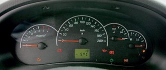
Niva controls
Controls of the VAZ-21213 GENERAL INFORMATION Controls
1 – horn switch; 2 – device composition panel; 3 – control wheel; 4 – shield fastening screw; 5 – external lighting switch; 6 – heater electric fan switch; 7 – windshield blower nozzles; 8 – central nozzles of the interior ventilation and heating system; 9 – control unit for the interior ventilation and heating system; 10 – rear window heating switch; 11 – plug; 12 – switch for rear fog lights; 13 – glove box; 14 – nozzles for blowing glass of front doors; 15 – shelf for a first aid kit, magazines and newspapers; 16 – plug; 17 – plug; 18 – socket for installing a radio receiver; 19 – gear shift lever; 20 – gear shift lever in the transfer case; 21 – ashtray; 22 – lever fixation key; 23 – parking brake lever; 24 – cigarette lighter; 25 – differential lock lever in the transfer case; 26 – rear window cleaner and washer switch; 27 – switch lever for windshield and headlight cleaners and washers; 28 – gas pedal; 29 – control lamp for covering the carburetor air damper; 30 – handle for closing the carburetor air damper; 31 – alarm switch; 32 – brake pedal; 33 – ignition switch; 34 – clutch pedal; 35 – direction indicator switch lever; 36 – fuse blocks; 37 – hood lock drive lever; 38 – plug; 39 – device lighting regulator; 40 – headlight hydraulic corrector; 41 – headlight switch lever; 42 – composition of devices
Shield Niva 21213
A transitional link between the classical and modern systems. The dial indicators and indicators are similar to the dashboard of the VAZ 2105, which many car enthusiasts do not like, and they want to change it.
Which panel is suitable for Niva 21213
Users often install panels from a VAZ 2114 or 2110 car. A minimum number of alterations and modifications will be required here. Contact groups and wiring terminals are reinstalled under the required pins. Refinement of plastic and seat will be required.
How to use a transfer case in a field, box design
The relatively complex scheme for distributing the torque from the internal combustion engine to the wheels is explained by the universally suitable purpose of the Niva 2121 - when used correctly, it can comfortably move around in the city and along a muddy country road. Such characteristics are ensured by the presence of a transfer case with a center differential lock, complementing a 4- or 5-speed manual transmission, depending on the year of manufacture. The lever, located closer to the dashboard , is responsible for turning off/on the center differential, the 2nd “small” lever controls the range multiplier and has 3 positions: high and low rows, also neutral.
Chevrolet Niva operating manual
The Niva Chevrolet manual describes the operation of the main vehicle systems: engine, brakes, amplifiers, electronics, and also provides guidance on setting up the equipment.
For easy reading of the Niva Chevrolet manual, select “Presentation mode” in the upper right corner of the pdf. You can also download the manual.
Design and principle of operation of the Niva 2121 transfer case
The transfer case mechanism includes more than 60 independent parts, which is confirmed by the presented drawing. Therefore, it is entirely prudent to name the main elements and their purpose.
- Housing Differential housing Shafts Couplings Seals Pinions Gears Flanges Levers
A pair of gears are tightly seated on the drive shaft, one of them (large) is designed for high gear, the 2nd (small) is responsible for low gear. They have serrations with straight and oblique profiles. The first ones are in contact with the coupling, the second ones are in contact with the intermediate shaft. The inclusion of one or another row sets the clutch in motion along the hub in the horizontal direction, after which it is connected to the gear on the transfer case drive shaft.
The middle position turns off the gearbox ( the gearbox is open ); moving the car in this mode is impossible. To control the differential, there is a front helical gear on the intermediate shaft. The locking is activated, or the rigid coupling of the drive shafts of both axles, is carried out through the clutch. The system is typical for modifications 21213 and 21214, while the latter is additionally equipped with a speed sensor drive.
In operating condition (with a transfer case reduction gear attached), the gear ratio in the first stage changes from 4.4 to 7.83, the 2nd - from 2.52 to 4.58, the third - from 1.63 to 2.9, to the fourth - from 1.2 to 2.14, the fifth - from 0.98 to 1.75, which is expressed in an increase in traction on the wheels.
Possible faults
If the instrument panel of the VAZ 21214 has stopped working, this may be caused by various reasons.
What malfunctions are typical for the device:
- Light bulbs don't work. If all the backlight fails at once, most likely the problem lies in poor power supply. If only a few or one lamp does not work, then the indicator should be replaced with a new one.
- The speedometer does not work. An electronic problem can be solved by dismantling the device and looking for a bad contact or a failed board element. The problem of tachometer breakdown is solved in the same way.
- Mechanical damage to the device due to impacts and other impacts on it. If the device stops working because of this, it must be removed and tested to determine the failed element.
- Broken wires, this malfunction can also be attributed to mechanical failures.
- Once connected, the new device may not work due to incorrect connection.
- Oxidation of the contacts on the plugs, which may cause sensors and controllers to not work. The problem is solved by cleaning the contacts.
Also interesting: Chevrolet Niva fuse box with description (up to 2009 model year)
How to use a transfer case with a range multiplier on a Niva 2121
The usual position for the RK handles, ensuring adequate behavior on the road of good quality:
- Front - away from you Back - towards you
The special mode of operation of the box is turned on not long before the car begins to overcome an obstacle (rut, mud, ford or rise). The transition to the lower row must be done while stopping. Returning to top gear is possible on the move, although it causes difficulties for beginners due to the lack of a conventional synchronizer. It is somewhat more difficult to correctly handle the forced manual locking of the center differential. On the contrary, it engages with small (up to 20 km/h) movement of the machine due to misalignment of the grooves on the locking clutch, satellites and ring gear. To make it easier to turn the lever into the required position, taking into account the Niva 2121 transfer case, pick up a low speed, then, shaking the steering wheel, pull the handle towards you.
Obstacles can also appear when the lock is turned off, since the clutch teeth practically cling to the crown. Engage reverse and, rocking the steering wheel, push the lever away from you. This action is done immediately after overcoming a difficult section in order to avoid overloading the checkpoint (Checkpoint - a point designed to control passage (visit) and access to the territory of any object)
. It is better to disable the differential along with the transition to lower stages. In this case, the Niva 4x4 can be stopped only by hanging the wheels diagonally, since standard inter-wheel locking is not provided. When performing the above operations, it is forbidden to give free rein to physical strength. An attempt to “push” the transmission will most likely result in costly repairs.
Possible problems
Harsh operation and insufficient attention to how to use the transfer case on the Niva 2121 lead to the appearance of:
- Vibrations in the body while moving Vibrations when starting Hum Noise when maneuvering Tight switching on modes
Experience shows that the culprits are: insufficient oil level, incorrect centering of the steering wheel, loosening of the support fastenings and damage to the rubber bands. An additional influence is exerted by the condition of the cardan and the engine itself.
All-wheel drive jeep VAZ-2121 "Niva". This car became a real sensation in the domestic automobile industry. Her appearance was preceded by numerous rumors, conjectures and gossip. The Soviet car enthusiast, not spoiled by the quality of roads, has long needed a comfortable passenger all-wheel drive SUV, which could be used with equal success both on asphalt and off-road. And in 1977, it rolled off the assembly line of the Volzhsky Automobile Plant - the first mass-produced all-wheel drive Niva.
It cannot be said that before the release of the Niva there were no off-road vehicles in the country. Were. True, mostly not civilian jeeps, but military cargo-passenger all-terrain vehicles, intended primarily for use in the armed forces. Of course, a certain number of these vehicles ended up in the national economy, but there were practically no all-terrain vehicles in personal ownership.
Nevertheless, the Soviet automobile industry has repeatedly made attempts to create comfortable passenger SUVs. Thus, back in pre-war 1938, a prototype of the first Soviet passenger all-terrain vehicle, intended for the senior command staff of the Red Army, was created at the Gorky Automobile Plant.
The car, named GAZ-61, was created on the basis of the GAZ-11-73 emka with a six-cylinder engine producing 85 hp. The car turned out to be extremely successful - on the highway with a full load, the all-wheel drive Emka reached speeds of up to 107.5 km/h, and its cross-country ability was such that even today it could easily compete off-road with the coolest modern jeeps. SUVs. Serial production of the GAZ-61 began at the beginning of 1941; it continued until August of the same year. Many of these vehicles survived the entire war; Such prominent Soviet commanders as G. Zhukov, I. Konev and K. Rokossovsky drove the GAZ-61.
In the post-war years, with the launch of the GAZ-M20 Pobeda car into production, the question of creating a domestic comfortable all-terrain vehicle was again raised - mainly for the party and economic leadership of rural areas. This SUV, called the GAZ-M72, was created on the basis of the Pobeda body and units of the GAZ-69 army all-terrain vehicle. This car became the embodiment of the concept of comfortable jeeps - foreign automobile companies did not even think about such cars at that time.
The first domestic passenger SUV GAZ-61 (1941)
All-wheel drive GAZ-M72 is a hybrid of the GAZ-69 army jeep and the Pobeda M-20 passenger car (1955)
Comfortable subcompact jeep "Moskvich-410" produced by MZMA (1957)
Rural SUV LyA3-969M based on the units of the Zaporozhets car (1979)
Experimental "Moskvich-416" based on the all-wheel drive vehicle "Moskvich-410N" (youth of the 1950s)
The domestic comfortable jeep VAZ-2121 is the first original development of the Volga Automobile Plant (1977)
The car was equipped with a transfer case with a range and a switchable drive front axle. With 16-inch wheels with increased lugs (such as the all-wheel drive Niva is now equipped with), the car had significant ground clearance, which provided it with good cross-country ability in mud, sand, snow, arable land and broken roads. The car was produced in a small series from 1955 to 1958. It’s a pity that the production of this kind of car was not properly continued - for our country, with its off-road conditions, such a car would be priceless. With the completion of the Pobeda production, the production of the GAZ-M72 also ceased.
The need for a similar all-terrain vehicle, however, not only remained, but even increased. In the 1950s, ordinary passenger cars “Muscovites” and “Pobeda”, which did not have all-terrain qualities, increasingly began to become the personal property of citizens. During these same years, the mass allocation of gardening and dacha plots to city residents began, which, as a rule, were cut off by off-road conditions from the few paved roads.