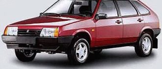
To help the auto electrician, all the electrical circuits of the Russian OKA car (VAZ-1111, VAZ-11113, VAZ-11116,) are collected here. Circuit diagrams are in high resolution, so click on it to enlarge or download to your computer to view in full screen. For greater reliability and convenience, several options for electrical circuits are provided. There is also a photo of the blocks, diagram and functions of all Oka relays and fuses. At the end of the article there are some tips on repairing and maintaining the electrical part of this car.
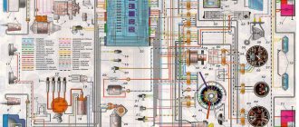
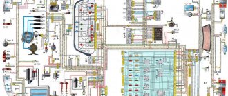
General wiring diagram
Content
- Headlights;
- Front direction indicators;
- Electric fan activation sensor;
- Sound signal;
- Electric engine cooling fan;
- Side direction indicators;
- New formation moment sensor;
- Spark plug;
- Ignition coil;
- Windshield washer pump motor;
- Accumulator battery;
- Generator;
- Oil pressure warning light sensor;
- Carburetor solenoid valve;
- Coolant temperature sensor;
- Reversing light switch;
- Switch;
- Plug socket for portable lamp;
- Brake fluid level sensor;
- Starter;
- Windshield wiper motor;
- Relay-breaker for direction indicators and hazard warning lights;
- Headlight high beam relay;
- Relay for low beam headlights;
- Starter activation relay;
- Electric fan switch relay;
- Fuse box;
- Parking brake warning light relay;
- Windshield wiper relay;
- Rear window wiper and washer switch;
- Rear window heating switch;
- Rear fog lamp switch;
- Carburetor choke warning lamp switch;
- Fog light circuit fuse;
- Carburetor air damper warning lamp;
- Hazard switch;
- External lighting switch;
- Heated rear window relay;
- Heater fan motor switch;
- Brake light switch;
- Cigarette lighter;
- Additional resistor for heater fan motor;
- Ignition switch relay;
- Ignition switch;
- Three-lever switch;
- Interior lighting;
- Lamp switches located in the door pillars;
- Instrument cluster;
- Parking brake warning lamp switch;
- Level indicator and fuel reserve sensor;
- Heater fan motor;
- Tail lights;
- Rear window wiper motor;
- Rear window heating element;
- License plate lights;
- Rear fog lamp;
- Rear window washer pump electric motor; A
- The order of conditional numbering of the plugs in the block of the spark torque sensor;
B
— The order of conditional numbering of plugs in the gear motor blocks of the windshield and rear window wipers and the windshield wiper relay breaker;
B
- The order of conditional numbering of plugs in the blocks of the ignition switch and three-lever switch;
D
- Order of conditional numbering of plugs in the instrument cluster blocks
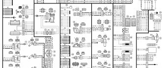
Wiring diagram SeAZ VAZ-11116
in high resolution (1 MB).
1/1 – High beam headlight lamp; 1/2 – Low beam headlights; 1/4 – Side light lamp; 2 – Front direction indicator lamp; 3 – Side direction indicator lamp; 5 – Generator with built-in voltage regulator; 9 – Hall sensor; 10 – Ignition coil; 12 – Starter Lada Oka; 13 – Spark plugs; 14 – Sound signaling device; 17 – Water temperature indicator sensor; 18 – Oil pressure warning lamp sensor; 23 – Battery; 25 – Reversing light switch; 26 – Brake light switch; 30 – Relay-breaker for direction indicators; 31 – Handbrake warning lamp relay; 32 – Windshield wiper relay; 33 – Additional resistance of the heater electric motor; 35 – Windshield wiper motor; 37 – Heater electric motor; 38 – Radiator cooling fan electric motor; 39 – Electric fan relay; 42/1 – Turn indicator switch; 42/2 – Headlight switch; 42/3 – Windshield wiper and washer switch; 42/4 – Horn switch; 44 – Ignition switch; 46 – External lighting switch; 48 – Hazard switch; 49 – Heater motor switch; 52 – Instrument cluster; 63 – Speed sensor Lada Oka; 74/1 – Thermal cigarette lighter element; 74/2 – Cigarette lighter lamp; 75 – Brake fluid level sensor; 76 – Handbrake warning lamp switch; 77 – Diagnostic block; 81 – Cartridge for connecting a portable lamp; 83 – Windshield washer pump; 87 – Interior lighting switch in the front door; 89 – Interior lamp; 93 – Sensor for level indicator and fuel reserve; 98/1 – Side light lamp; 98/2 – Direction indicator lamp; 98/3 – Brake light lamp; 98/4 – Reversing lamp; 99 – License plate light lamp; 104 – Electric fan thermal switch; 108 – Rear fog lamp; 112 – Rear window wiper motor; 113 – Rear window washer motor; 115 – Rear window heating element; 121 – Relay for turning on the heated rear window; 125 – Additional relay; 126 – Headlight high beam relay; 127 – Relay for low beam headlights; 129 – Starter relay; 133 – Rear window heating switch; 136 – Rear fog lamp switch; 137 – Rear window wiper switch; 138 – Rear window washer switch; 158 – Fuel injectors; 159 – OKA watch; 168 – Relay for rear fog lights; 169 – Additional brake signal; 170 – Fuel pump relay; 171 – Electric fuel pump; 172 – Idle speed regulator; 173 – Throttle position sensor; 174 – Knock sensor; 175 – Canister purge valve; 176 – Oxygen sensor; 177 – Absolute pressure sensor; 178 – Main relay; 221 – Controller.
Useful: Pinout and diagram of a fuel pump with a VAZ relay
Windshield wiper and washer diagram
- Windshield washer motor;
- Windshield wiper motor;
- Ignition switch;
- Fuse box;
- Windshield wiper and washer switch;
- Conventional numbering of plugs in the switch block;
- Windshield wiper relay;
- Conventional numbering of plugs in the relay blocks and the windshield wiper motor.
Maintenance, repair
Of all the car’s electrical appliances, only power supplies require maintenance:
- Battery (periodic recharging using chargers, monitoring the level and density of the electrolyte);
- Generator (periodic check of drive tension, replacement of worn graphite brushes).
It is also important to monitor the condition of the wire insulation and prevent it from being damaged to avoid a short circuit. Oxidation of contacts often occurs at the wiring junctions, which can lead to failure of electrical appliances.
Most of the electrical network components are maintenance-free and must be replaced if they fail. Such elements include light bulbs, small electric motors, switches, relays, fuses, and sensors.
In the starter, generator, electric. In the heater and cooling system fan motors, mechanical breakdowns may occur - wear of bearings, bushings, brushes. All these components are repairable and it is often possible to restore their functionality by disassembling, troubleshooting and installing new parts to replace worn ones.
Rear window cleaner and washer
- Fuse box;
- Tailgate wiper and washer switch;
- Tailgate glass washer motor;
- Tailgate glass wiper motor;
- Tailgate glass heating element;
- Tailgate glass heating relay;
- Tailgate glass heated switch;
- Ignition switch.
Common faults
All malfunctions in the wiring on the VAZ 2111 Oka can be divided into several groups:
- Failure of the device itself. For example, if we are talking about headlights, then the lamps in them may burn out. If the rear window heating system refuses to work, then the unit itself may be faulty.
- Broken electrical wiring. As a rule, this problem is more relevant for wires that are laid in places where there are moving or rubbing elements. For example, wires from door locks are laid in the doors themselves, and to connect to the fuse box they are laid in special rubber corrugations. Despite such protection, wires can also break in the corrugation.
- No contact. The lack of contact may be due to either a broken wire or oxidation of the contact; in some cases, it may simply move away from the installation socket. In case of oxidation, the problem is solved by stripping.
- The fuse or relay has blown. This happens especially often in cars where there are power surges. The fuse simply cannot withstand the power of the on-board network and fails, thus protecting the device from burnout. If your car actually has power surges, then you need to either check the on-board network yourself or contact an electrician.
- Also one of the most common malfunctions is battery discharge. Car owners usually face this problem with the onset of cold weather; in some cases, it may be due to improper maintenance (the author of the video is the Milin0915 channel).
Low/high/fog beam diagram
- Headlights;
- Fuse box;
- Relay for low beam headlights;
- Ignition switch;
- Fog light switch;
- Rear fog light;
- High beam indicator lamp;
- External lighting switch;
- Fog light circuit fuse;
- Headlight switch;
- Headlight high beam relay.
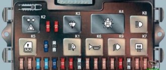
Relay block
On the left side under the instrument panel there is a block of five identical relays (90.3747-10 / 113.3747-10 / 2105-3747210-20)
p, blockquote 9,1,0,0,0 —>
Scheme
Designation
| 1 | Engine radiator fan relay |
| 2 | Low beam relay |
| 3 | High beam relay |
| 4 | Starter relay |
| 5 | Heated rear window relay |
Diagram of hazard warning lights and direction indicators
- Front direction indicators;
- Ignition switch;
- Hazard switch;
- Turn signal switch;
- Side direction indicators;
- Turn signal lamps in the rear lights;
- Turn signal indicator lamp (in the instrument cluster);
- Relay-breaker for direction indicators and hazard warning lights;
- Fuse box.
Prevention measures
What you need to consider to prevent problems with electrical equipment:
- If you notice voltage surges or short circuits, immediately contact an electrician or fix the problem yourself.
- Carry out regular battery maintenance, at least twice a year. During maintenance, pay attention to diagnosing the liquid level in the cans, inspect the body for damage, and also charge the battery to replenish its discharge.
- When laying wiring, all wires must be securely insulated.
- Do not turn on the appliances, radio or heater at full power if the engine is not running. This will cause the battery to drain faster.
- Never install homemade safety devices (in the form of a jumper, wire or coin) into the fuse box.
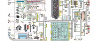
Instrument cluster diagram
- Coolant temperature indicator sensor;
- Fuel level indicator with reserve indicator lamp;
- Indicator lamp for brake fluid level and parking brake system;
- Oil pressure warning lamp;
- Coolant temperature gauge;
- Fuse box;
- Ignition switch;
- Parking brake warning lamp switch;
- Parking brake warning lamp relay;
- Brake fluid level sensor;
- Oil pressure warning light sensor;
- Level indicator and fuel reserve sensor.
- Headlight high beam warning lamp;
- Coolant temperature gauge;
- Side light indicator lamp;
- Turn signal indicator lamp;
- Instrument cluster lighting lamp;
- Battery discharge warning lamp;
- Oil pressure warning lamp;
- Fuel level and reserve indicator;
- Fuel reserve indicator lamp;
- Indicator lamp for parking brake system and brake fluid level.
Common electrical faults
Common problems with electrical equipment on VAZ-1111 and 1113:
- Failure of external lighting devices. A common cause of failure is burnt out lamp filament; the unit must be replaced. If the light bulb is intact, then there may be a defect in the electrical wiring, due to which a short circuit occurs and the fuse fails. The fuse link is replaced with an identical one; it is prohibited to use parts designed for a higher current. It is also unacceptable to install homemade jumpers (“bugs”), as this can cause a fire. If a repeated burnout occurs, it is necessary to check the circuit and eliminate the wiring fault.
- Wire breaks occur at points where the insulation is subject to bending or friction against moving surfaces. An example of such a point is the junction of the door and the body. Damaged areas must be replaced with products made of similar material with an identical cross-section.
- Oxidation of contact surfaces due to moisture or aggressive liquids (for example, battery electrolyte). It is necessary to clean the surfaces down to metal, restoring the transmission of electric current.
- Relay failure associated with burnt contacts or coil breakage. The unit cannot be repaired; it must be replaced with a new one. In the event of a rapid re-failure, the vehicle's electrical system must be checked at a car service center.
- Sudden battery discharge is due to an internal short or current leakage. In winter, a partially charged battery may lose capacity due to low air temperatures. You need to charge the battery and check the condition of the wiring. If necessary, the power source must be replaced.
- Pulsating operation of external lighting lamps with an unusually bright glow indicates a breakdown of the relay regulator on the generator. Repair requires removing the unit and replacing failed components.
- Insufficient battery charge (the warning light does not go out when the engine is running). The cause may be wear on the brushes or commutator, or insufficient tension on the drive belt. The generator needs to be repaired, since the battery charge is enough for 150-200 km during the daytime.
- Poor contact between the ends of the cylindrical fuses and the spring-loaded elements in the mounting block. It arises due to the design features of the unit. Many owners, tired of dealing with the defect, install homemade blocks for knife inserts. Usually a short section from the GAZ-3110 is used, designed for 13 seats. There are self-assembled units designed for fuses and relays.
conclusions
Many advantages are provided by such a simple unit in a contactless ignition system as a switch. This includes an increase in power, even if only slightly, a reduction in fuel consumption, and a significant improvement in the engine in terms of reliability. And most importantly, there is no need for constant monitoring and timely adjustment of the system. The modern driver does not want to repair a car, he needs a means of transportation. Moreover, it is reliable and will not let you down at the most crucial moment. Regardless of which switch is used in the BSZ, its efficiency is much higher than that of a contact breaker.
Connecting the switch
Cases vary, and it is possible that you will have to change the wiring. Therefore, you will need to take into account the purpose of all pins on the switch plug. This will allow the connection to be made correctly, and there will be no risk of damaging it. The first pin of the switch is the output. In other words, the amplified signal is removed from it. It must be connected to the terminal of the “K” coil. The second contact is connected to ground - the negative of the battery.
All three wires from the Hall sensor go to the VAZ switch. Moreover, the signal wire is connected to the sixth terminal of the switch. The fifth is the power output (the voltage on it is stable 12 Volts). The third output of the switch is ground (minus power). The third is connected inside the block to the second. But between the fourth, which is supplied with power from the battery, and the fifth there is a constant resistance and a voltage stabilizer.
Main devices
This car, VAZ Oka, in terms of the design of its engine is almost no different from any other car from this plant, the same classic. If we take it apart, we will see just half of the engine from the VAZ 2108, in which the pistons move synchronously. Because of this, two balancer shafts had to be added to balance the motor. Everything else is already taken ready, the same brakes, cooling system and ignition system.
A non-contact ignition is installed here, the same one that can be found even on the modernized VAZ 2101. It includes:
- Spark sensor.
- Switch.
- Ignition coil.
- Candles.
- Relays and high-voltage wires.
We won’t dwell on the topic of how exactly the ignition works on the VAZ Oka, since it works like any contactless ignition on a classic.
Spark plug
The spark plug is designed to ignite the combustible mixture in the cylinders by a spark discharge between the electrodes. Oka cars can be equipped with FE65PR or FE65CPR spark plugs made in Bosnia. The difference between the FE65CPR spark plug is that it has a copper core in the central electrode to improve heat dissipation from the end of the electrode to the body (this is indicated by the letter C in the designation of the spark plug). The letter F in the designation indicates that the spark plug body has an M14X1.25 thread, and the second letter (E) indicates that the length of this thread is 19 mm. The numbers (65) characterize the glow number of the candle. The letter P means that the thermal cone (skirt) of the insulator protrudes beyond the end of the housing, and the letter R means that the spark plug has a certain internal resistance to suppress radio interference.
Similar domestically produced spark plugs A17DVR, or A17DVRM, or A17DVRM1 can also be installed.
The design of the candles is non-separable. In the steel housing 22, a ceramic insulator 20 is rolled, inside of which there is a composite electrode consisting of a contact rod 21 and a central electrode 26. The side electrode 27 is welded to the housing. The lower part of the rod 21 and the upper part of the central electrode are filled with a special conductive glass sealant 23 with a resistance of 4...10 kOhm. It prevents gases from breaking through the insulator hole and at the same time acts as a resistor to suppress radio interference. To prevent gas leakage through the body thread, a sealing washer 24 made of soft iron is used, which is clamped between the spark plug body and the end surface of the socket in the cylinder head.
The gap between the spark plug electrodes should be within 0.7...0.8 mm. It is adjusted by bending the side electrode 27. It is not allowed to adjust the gap by bending the central electrode, since the insulator skirt can be broken. When the spark plug operates, metal is transferred from the side electrode to the center electrode. As a result, a notch is formed on the side electrode, and a tubercle is formed on the central electrode. Therefore, it is necessary to check the gap between the spark plug electrodes not with a flat, but with a round wire probe.
The gap between the spark plug body and the insulator is sealed using a steel washer 25 and heat-setting of the body. Thermal shrinkage consists of heating the body belt (under the hexagon) with high frequency currents to a temperature of 700...800 ° C and subsequent crimping of the body with a force of 20...25 kN. Washer 25 simultaneously serves to remove heat from the insulator to the body, maintaining the temperature of the insulator skirt at a certain level.
The temperature of the insulator during engine operation mainly depends on the length of the skirt and on the thermal stress of the engine. The longer the skirt, the worse the heat dissipation from the skirt to the body and the “hotter” the spark plug. The optimal temperature of the insulator skirt should be within 500...600 ° C. If the temperature is below 500 ° C, i.e. the skirt is short and the spark plug is “cold”, then soot will be intensively deposited on the insulator skirt. If the temperature is above 600° C, then the carbon deposits will burn, but the engine will experience premature ignition of the combustible mixture from the heated skirt, and not from a spark. This phenomenon is called glow ignition. It is manifested by knocking in the engine and the fact that after turning off the ignition the engine continues to run for some time.
Glow ignition is a harmful phenomenon. It leads to a decrease in power and to overheating of the engine, to premature wear of its main parts, and can cause cracks in the spark plug insulators and burnout of the electrodes.
To assess the ability of a candle to glow ignition, its designation includes the glow number - an abstract value proportional to the average indicator pressure in the engine cylinders at which glow ignition occurs. It is determined on special single-cylinder engines by gradually increasing the operating pressure (and therefore temperature) in the cylinder. The greater the pressure in the cylinder at which glow ignition occurs, the greater the glow number, i.e., the “colder” the spark plug.
For each engine model, the spark plug is selected individually according to its heat rating. Therefore, it is not allowed to use any other spark plugs other than those indicated above on Oka cars.
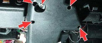
Installation and repair of a starter in an OKA car (VAZ-11111)
Skoda octavia fuses (Skoda Octavia) a5: where are they located, replacement
Like any internal combustion engines of passenger vehicles, the power units of the Oka car modifications 1111, 11113 are started using a starter - a power electric motor with remote control. The task of this unit is to spin the crankshaft to create the necessary conditions for ignition of the air-fuel mixture.
Models, characteristics, location
The designers did not borrow a starter from other VAZ models, but made a new one - for Oka engines. The impossibility of unifying starters for owners of this small car often results in problems, since the “native” starter is not a particularly reliable unit.
It is noteworthy that Oka’s power electric motors were produced by several manufacturers. The most common is the unit with the factory index 39.3708 (KZATE Samara plant), which we will consider in the future. Also, the VAZ-1111 was equipped with Belarusian-made components (1111-3708010-5) and Slovenian ones - AZE-1517.
The main characteristics of model 39.3708 are as follows:
- Power – 0.9 kW;
- Current consumption – 230A;
- Weight – 5 kg;
This unit is mounted on the left side of the engine (in the direction of travel) above the gearbox, and the thermostat housing is located above it. Fixation is carried out with only two fasteners - a bolt and a nut, with which the starter is attracted to the clutch housing. This arrangement is convenient because you can dismantle the unit from the car without removing anything additional.
The starter on the Oka is a commutator electric DC motor. Its main components are:
- Stator with field windings;
- Brush holder (brush assembly) with 4 graphite brushes;
- Anchor;
- Bendix (drive gear with freewheel);
- Solenoid relay with drive plug;
- Lids;
All elements are assembled into a single structure and secured with coupling bolts.
The stator due to the passage of electrical energy through its windings, ensures the emergence of an electromagnetic field. The second magnetic field is created by the armature winding. Electric current is supplied to it through graphite brushes to the commutator, to the plates of which the ends of the armature winding are soldered. The magnetic fields generated around the windings lead to the rotational movement of the armature.
On one side of the armature shaft there are splines on which a bendix is mounted, consisting of a gear and an overrunning clutch. Bendix has the ability to move along the shaft, and due to the spline connection, rotation is transmitted to it.
How does a switch work?
Essentially, a switch is a simple signal amplifier. It can even be compared to a Darlington assembly, which is used in microcontroller technology to convert a weak signal from an output port to the required level. The basis of this assembly is field-effect transistors operating in switch mode. An operating voltage is applied to them, a signal is sent to the control terminal, which is amplified and removed from the collector.
The ignition switch has an almost similar operating scheme. Only the signal from the Hall sensor is used. It has three outputs - control, common, plus power. When a metal plate appears in the sensor area, a current is generated, which is supplied to the input of the switch. Next, the signal is amplified and supplied to the primary winding of the coil. The entire system is powered only after the ignition is turned on (after turning the key).
Ignition coil
Content
The ignition coil is high energy grade 29.3705, with two high-voltage terminals and an open magnetic circuit. It is attached with two nuts to the bracket on the mudguard of the left wheel.
The ignition coil has a core 4 made of thin electrical steel plates. A primary (low-voltage) winding 5 is wound on top of the core on a cardboard frame, and then a secondary (high-voltage) winding 2. The layers of windings are separated by electrically insulating paper, and the windings are insulated with plastic. The ends of the primary winding are soldered to plugs 3, and the secondary windings are soldered to sockets 6. The core with windings is filled with plastic. The resistance of the primary winding is (0.5±0.05) Ohm, and the secondary winding is (11+1.5) kOhm.
On Oka cars, an interchangeable ignition coil type 3012.3705 can also be used. It is a transformer with a core made of W-shaped electrical steel plates. The windings are powered by insulating plastic. The resistance of the primary winding of coil 3012.3705 is (0.35±0.035) Ohm, and the secondary winding is (4.23±0.42) kOhm.
How to check
There is nothing complicated in this procedure. The easiest way is to use a known-good node, since you can check the switch this way in literally a matter of minutes. But if there is none, and you need to determine exactly whether the fault is in the coil or in the switch, it is wiser to use other methods. You will need a simple incandescent lamp. If you don’t know where to get it, then unscrew it from the interior lamp or from the side lights.
Connect one terminal of the lamp to the negative of the battery. Connect the second one to pin “1” of the switch. This is the same pin from which the amplified signal is removed. If the lamp lights up, then the device is working properly. A more advanced testing method is carried out using an oscilloscope. On the screen you can see the magnitude and shape of the signal, and also compare it with the reference one.
Additional relays
Depending on the configuration and design, additional relay placement is possible.
p, blockquote 13,0,0,1,0 —>
Scheme
Purpose
- Hazard warning and direction indicator relay (494.3747 / 2105-3747010-01) - located behind the instrument cluster.
- Front wiper relay (RS-514 (2101-5205150)) - located under the upholstery, left side panel.
- Parking brake warning lamp relay (RS-492 (2101-3803150)) - located behind the instrument cluster, next to the turn signal relay (see point 1).
- Additional relay (90.3747-10 / 113.3747-10 / 2105-3747210-20).
- Ignition relay (90.3747-10 / 113.3747-10 / 2105-3747210-20) - secured with a self-tapping screw from inside the instrument panel.
High voltage wires
The wires transmit high voltage pulses from the coil to the spark plugs. They can be of two brands: PVVP-8 or PVPPV-40. Due to the increased thickness of the insulation, they have an outer diameter of 8 mm instead of 7 mm for the wires of a conventional ignition system.
The core of the wire is a cord 32 of flax fiber, enclosed in a sheath 31 of plastic with the maximum addition of ferrite. On top of this shell is a conductive winding made of an alloy of iron and nickel. This wire design has resistance distributed along its length and reduces radio and television interference. The winding resistance is 2000±200 Ohm/m for PVVP-8 wires and 2550±270 Ohm/m for PVPPV-40 wires. On the outside, the wire is insulated with red polyvinyl chloride compound (PVVP-8 wires) or blue irradiated polyethylene (PVPPV-40 wire).