Lada Vesta, like all modern cars, has a large amount of electronics and electrical equipment. In order for this whole thing to work and function properly, the car requires electrical wiring, which, like the veins in the human body, literally permeates the entire body of the car. If we pull out all the wiring of the Lada Vesta and measure its length, we will get a figure of several hundred meters.
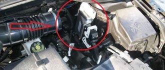
The need to study electrical circuits most often arises when an element breaks down or fails. In this case, it is necessary to correctly diagnose and establish the cause of the breakdown - to “sentence” the element itself or the wiring to replacement. Let's look at a small example. The car lost idle speed. The diagnostics revealed an error in the XX regulator. There may be several reasons - either the regulator itself has failed, or poor contact on the wire chips, or a break in the wiring. Before buying a regulator, you need to make sure that the problem is not a broken electrical circuit. We can do this with a tester and test the wiring. But here's the problem. The IAC wires are located under the hood, and control comes from the ECU in the cabin. So what should we do? In this case, the Lada Vesta electrical diagram will help us. Using the diagram, we can find where the contact is coming from the ECU to the IAC and make a call without any problems. This is a seemingly very simple situation, but without knowledge of the Lada Vesta electrical circuit it would not be possible to solve it in a short time.
In this article you will find all the electrical equipment diagrams of the Lada Vesta with a detailed description. So, let's go.
Connection diagram for rear auxiliary wiring harness
Front left door wiring harness connection diagram
Where can I buy?
You can buy it at a dealership, but in the showroom it is usually very expensive. As an alternative site, you can use the resources presented in the table below. However, it is worth considering that prices may vary, and the part is not always available.
| Online store | vendor code | Price, rub.) |
| lada-vesta-shop.ru | 231A03142R | 10100 |
| www.zzap.ru | 231A03142R | 7430-8890 |
| autopiter.ru | 231A03142R | 11511 |
| avtoazbuka.net | 231A03142R | 8888 |
| renault-largus.ru | 231A03142R | |
| www.auto-tech.ru | 231A03142R | 8890 |
| www.avtogrin.ru | 231A03142R | 10500 |
As you can see, the price of an additional Vesta body electronics unit is quite high, so the replacement is not cheap. However, all work in the service center takes no more than 60 minutes.
Problems when paying with bank cards
Sometimes difficulties may arise when paying with Visa/MasterCard bank cards. The most common of them:
- There is a restriction on the card for paying for online purchases
- A plastic card is not intended for making payments online.
- The plastic card is not activated for making payments online.
- There are not enough funds on the plastic card.
In order to solve these problems, you need to call or write to the technical support of the bank where you are served. Bank specialists will help you resolve them and make payments.
That's basically it. The entire process of paying for a book in PDF format on car repair on our website takes 1-2 minutes.
If you still have any questions, you can ask them using the feedback form, or write us an email at
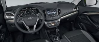
Description of functions
A review of the Lada Vesta on-board computer shows which parameters are displayed on the display or front panel display. This makes the life of a Lada car enthusiast much easier. On Vesta, the standard on-board computer shows the following information, in addition to error codes:
- The magnitude of the vehicle network voltage;
- Cruising range on fuel in the gas tank;
- Current and average fuel consumption;
- Remaining fuel in the tank;
- Travel time along a specific route;
- Average speed;
- Watch;
- Total mileage;
- Controls the outside air temperature;
- Gives gear shift hints (with or without sound);
- On a Lada with cruise control, information about the installed parameters is displayed;
- If there is an AMT, the gear engaged or the auto - manual mode is displayed.
On-board computer Lada Vesta The on-board computer on the Lada Vesta is configured using two keys on the right steering column switch. Using the keys, entering the menu, you can control the readings of Vesta BC, displaying the necessary data on the control panel. Thus, the driver constantly has the opportunity to control the required parameters of Vesta.
Settings
After reading the operating instructions, operating the on-board computer will not seem difficult. In order to set or manage parameters, press the up key and hold for a while. We get to the settings menu, where you can:
- Set time;
- Reset previous mileage;
- Reset average flow and average speed.
Setting the clock
Some car owners have a question about how to set the clock. For this:
- Press the top key (hold it for about 3 seconds) to enter the editing mode.
- The previously set time is displayed on the screen.
- Again holding the top button for about 2 seconds.
- The first value, the clock, starts blinking. Use the arrows to set the required value.
- Hold up again and go to setting the minutes.
- After the time has been set, it is necessary to secure the readings. To do this, you again need to hold the up key for a long time.
The time setting is complete.
Description of fuses on a Lada Vesta car: location, diagram, price
Lada Vesta cars are equipped with knife-type modules in the following modifications:
The manufacturer abandoned the installation of cylindrical modules 7 years ago due to the obsolescence of the model.
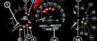
Relay-breaker layout diagram
| Designations | Who is responsible for what/what provides |
| K 1 | Lighting, seat heating |
| K2 | Responsible for the cigarette lighter |
| K 3 | Heated rear window |
| K 4 | Front windows |
| K5 | Interior heater (stove) |
| K 6 | Window lifter for rear doors |
| K 7 | Gasoline pump |
| K 8 | Car socket (powered by 12 Volts) |
| K9 | Heated windshield |
| K 10 | Heating relay |
| K11 | Starter |
| K 12 | Sound signal |
| K 13 | Beep (optional) |
| K 14 | Relay KSUD |
| K 15 | Air conditioning system |
| K 16 | Compressor clutch |
| K 17 | Cooling fan |
Lada Vesta fuse installation diagram
| Marking/amperage | What he is responsible for (with description) |
| F (F-1) / 20 | Windshield washer |
| F (F-2) / 5 | Understeering's shifter |
| F (F-3) / 10 | High beam (left headlight) |
| F (F-4) / 10 | Steering column switch (left) |
| F (F-5) / 20 | Heated seats |
| F (F-6) / 30 | Side lights (right) |
| F (F-7) / 30 | Left dimensions |
| F (F-8) / 7.5 | Rear fog lights |
| F (F-9) / 10 | Right turn signal repeaters |
| F (F-10) / 10 | Automated gearbox selector |
| F (F-11) / 10 | Low beam (left side) |
| F (F-12) / 10 | Direction indicators |
| F (F-13) / 30 | Power circuit |
| F (F-14) / 30 | Stop signals |
| F (F-15) / 10 | Rain sensor, external lighting, hydraulic headlight range control |
| F (F-16) / 15 | Stop light (optional) |
| F (F-17) / 15 | Illumination of the glove box, thresholds |
| F (F-18) / 10 | Turn signal repeaters (left) |
| F (F-19) / 10 | Low beam (right) |
| F (F-20) / 10 | Heated mirrors (external) |
| F (F-21) / 5 | Instrument panel (panel) |
| F (F-22) / 5 | –/– |
| F (F-23) / 5 | –/– |
| F (F-24) / 5 | ERA GLONASS |
| F (F-25) / 5 | ES9.1 controller |
| F (F-26) / 5 | Gasoline pump |
| F (F-27) / 20 | Parktronic |
| F (F-28) / 15 | Electric power steering |
| F (F-29) / 15 | Line output to tow hitch |
| F (F-30) / 20 | ERA GLONASS (optional) |
| F (F-31) / 15 | ERA GLONASS (optional) |
| F (F-32) / 15 | Engine compartment lighting |
| F (F-33) / 5 | Window lifters |
| F (F-34) / 15 | Steering wheel rotation sensor |
| F (F-35) / 5 | Door program block |
| F (F-36) / 15 | Radio, diagnostic connector |
| F (F-37) / 15 | Stop light (optional) |
| F (F-38) / 15 | Stop light (optional) |
| F (F-39) / 15 | Daytime Running Lights |
| F (F-40) / 20 | High beam (right) |
| F (F-41) / 20 | Standard cigarette lighter |
| F (F-42) / 20 | Bus power |
| F (F-43) / 20 | Door locks |
| F (F-44) / 20 | Window lifters |
| F (F-45) / 20 | Heater fan (interior) |
| F (F-46) / 20 | Windshield wiper (windshield wipers) |
| F (F-47) / 15 | PDS, LBS, LGO |
| F (F-48) / 15 | Windshield wiper (optional) |
| F (F-49) / 15 | PTF, ZPTO, license plate |
| F (F-50) / 15 | PDS, LBS, LGO (optional) |
| F (F-51) / 70 | Electric power steering |
| F (F-52) / 30 | Heated rear window |
| F (F-53) / 40 | Stability Program (ESP) |
| F (F-54) / 15 | Air conditioning system |
| F (F-55) / 5 | Reservation |
| F (F-56) / 15 | Automatic transmission |
| F (F-57) / 15 | Reservation |
| F (F-58) / 70 | Transmission optional |
| F (F-59) / 15 | Air conditioner |
| F (F-60) / 15 | Fuse supply circuit |
| F (F-61) / 60 | Generator |
| F (F-62) / 10 | Beep (optional) |
| F (F-63) / 5 | Reversing light |
| F (F-64) / 15 | Anti-theft alarm |
| F (F-65) / 15 | central locking |
| F (F-66) / 20 | Canister, air flow sensor, timing valve |
| F (F-67) / 15 | Fuel pump, charging |
| F (F-68) / 15 | Reservation |
Causes of fuse failure
- Failure to comply with the scheduled technical inspection schedule;
- Installation of non-original spare parts;
- Unprofessional installation;
- Mechanical damage to adjacent mechanisms and units;
- Short circuit in the wiring;
- Damage to the insulating layer;
- Oxidation of contacts;
- Loose fixation of terminal blocks;
- Condensation formation, moisture penetration into the structure.
Removing and installing the ignition switch
If, while checking the switch with a multimeter, it turns out that it is time to change it, you need to act. To begin, perform the same steps on your Vesta as when checking:
- Stop the car, remove the negative terminal.
- Remove the steering column covers, release the lock of the immobilizer wire block, and disconnect the switch from the network.
- Place the chisel under the cap of one of the bolts securing the switch to the steering column. Tap it slowly until the bolt comes out counterclockwise.
- Tighten it using pliers.
- Before installation, insert a new key and turn it to the third position. Secure the switch housing in place and reassemble the steering column.
OBD 2 pinout
Brands and years:
Gasoline passenger cars and light commercial vehicles manufactured or imported into the United States since 1996 (US CARB and EPA legislation) and in Europe (EOBD) since 2000-2001 (European Union Directive 98/69EG) and Asia (mainly since 1998). ).
Conclusions and their purpose:
| № | Color | Purpose |
| 2 | J1850 Bus + | |
| 4 | Body grounding | |
| 5 | Signal Ground | |
| 6 | Line CAN-High, J-2284 | |
| 7 | K-line diagnostics (ISO 9141-2 and ISO/DIS 14230-4) | |
| 10 | J1850 Bus- | |
| 14 | Line CAN-Low, J-2284 | |
| 15 | L-line diagnostics (ISO 9141-2 and ISO/DIS 14230-4) | |
| 16 | Power supply +12V from battery |
Diagnostic connector pins for used protocols
Pins 4, 5, 7, 15, 16 - ISO 9141-2.
Pins 2, 4, 5, 10, 16 - J1850 PWM.
Pins 2, 4, 5, 16 (without 10) - J1850 VPW.
The ISO 9141-2 protocol is identified by the presence of pin 7 and the absence of pins 2 and/or 10 on the diagnostic connector.
If pin 7 is missing, the system uses the SAE J1850 VPW (Variable Pulse Width Modulation) or SAE J1850 PWM (Pulse Width Modulation) protocol.
All three data exchange protocols operate via a standard OBD-II J1962 connector cable.
Methods for diagnosing ECUs and errors on Lada Vesta via OBD2
Let's look at examples of analyzing machine systems in different ways.
Check Engine light on Vesta?
Detailed article on the causes of Check Engine and how to clear the Check. If your Check Engine light comes on, read this article immediately. The material explains what a Check Engine is, what to do if it appears, and how to remove this error yourself.
Is the Check Engine light on?
TOP 15 reasons why the Check Engine light comes on and ways to solve the problem. Read the article to solve the Check Engine problem.
To enter the BC diagnostic mode, hold down the top key and turn on the ignition.
Reviews of diagnostic scanners for LADA VESTA
Read detailed articles on the review of car scanners, including those compatible with LADA VESTA.
Reviews of OBD2 diagnostic car scanners
This section provides descriptions of diagnostic scanners and adapters. Before purchasing a scanner for your car, it is recommended that you read reviews of the most popular equipment models.
New software is written using programmers. There are open and closed ECUs.
- In a diagnostic way. Without removing the ECU from the vehicle via the diagnostic connector using flash loaders and a program such as Combiloader.
- Work via BSL mode of the ECU processor. With this method, programming the ECU is carried out by removing the latter from the car using bootloaders that work with the ECU processor via BSL mode.
On-board computer control algorithm
1. Selection of on-board computer functions (carried out using the keys on the right steering column switch).
2. Selecting trip meters and switching between clock and temperature.
3. Enter parameter setting mode, select parameter.
3.1. Setting the time.
When you exit the time setting mode, the seconds counter is reset to zero (reset without rounding). If there are no button presses within 60 seconds, the time setting mode will exit automatically.
4. Display mode of parameters of the “Cruise control” or “Speed limiter” functions.
In the mode of displaying the parameters of the “Cruise control” or “Speed limiter” functions, it is possible to switch the displayed function of the on-board computer (point 1) and the total and daily mileage counters (point 2), the indication of outside air temperature and time is not available, parameter setting modes (point 3 ) are not available.
- “short” – press for less than 1.5 seconds, triggered when released.
- “long” – press for more than 1.5 seconds, triggered by time.
- yellow color – the segment is blinking (square wave, 1 Hz).
- When resetting the route parameters (clause 3(d)), the following parameters are reset to zero: average fuel consumption, fuel consumed, travel time, average speed.
Bookmaker settings are also shown in the video:
To change the sound of the turn signals, you need to go to the secret menu (it does not work on the instrument cluster). To do this, press two BC buttons at the same time. More detailed instructions in the video:
Are you satisfied with the functions of the Lada Vesta on-board computer? Let us remind you that other operating instructions for this vehicle can be found in this section.
It is difficult to imagine a modern car without an on-board computer (alternative names: “BC”, “carputer”, “onborder”), which allows you to increase engine efficiency, reduce gasoline consumption, optimize the operation of the gas distribution system and synchronize the interaction of all units. In addition to the above, BC reduces the concentration of harmful emissions. The onborder performs the functions of cruise control, climate control, and displays the information necessary for the driver, allowing him to make the right decisions on transport management and optimal movement along the chosen route. That is why all modern Lada Vesta models are equipped with BCs that successfully perform the functions assigned to them.
MMC malfunctions and methods for their elimination
Obviously, the standard radio is one of the first developments of the AvtoVAZ concern; there are defects and shortcomings. For example, the display does not load the “LADA” logo:
- We remove the digital storage medium from the connector.
- Disconnect the power terminal from the battery for 10 seconds.
- On the laptop, format the SD card in FAT 32 format, create an empty file “explorer.txt” in the root directory.
- We connect the battery terminals and restart the audio system.
If this method does not help, then problems with the software code of the electronic control unit are obvious. You need to reflash your digital gadget.
The second, no less common malfunction is “cannot find satellites.”
The solution to the problem is quite simple:
- Remove the power terminals from the battery.
- Reset the device to factory settings.
- We restart the gadget again.
To reset to factory settings, you must hold the “Power” button for 15 seconds.