Correctly adjusting headlights does not always ensure safe driving. This is due to the fact that any change in the vehicle's suspension height, which may be caused by loading the trunk or the presence of passengers, leads to a change in the trajectory of the light flux. This in turn may reduce road illumination or dazzle oncoming drivers. To constantly adjust the position of the optics axis in the vertical plane, depending on the degree of vehicle load, special devices are used - headlight correctors; do not confuse them with automatic headlight switching sensors.
Today, various types of autocorrectors are produced that maintain a given vertical position of the axis of the head optics relative to the angle formed between the axes of the car frame (floor, body) and suspension. Depending on the design features and operating principle, headlight range control units can be quasi-static or dynamic.
Rules for adjusting car headlights
Changing the direction of the axis of the light beam when adjusting the headlights is ensured by rotating the parabolic reflector, the focus of which is the light bulb, by moving it relative to the vertical and horizontal planes.
The correct position of the reflector is established by two vertical and horizontal adjustment screws, which are located on the rear surface of the headlight unit.
To correctly adjust the headlights, it is necessary to combine the light spot formed by the optics with the reference adjustment diagram, which is usually provided by the car manufacturer (in our case, the headlight adjustment diagram for Tavria and Slavuta cars).
Car headlight adjustment diagram
The headlights are adjusted in the following order:
- An unloaded car is placed on a flat horizontal platform at a distance of 5 meters from the screen. Any wall or low fence (up to one meter) is quite suitable as a screen.
- A vertical line “0” is applied to the screen, lying in the plane of symmetry of the machine (look at the adjustment diagram). To the left and right of it, two more symmetrical lines “L” and “R” are drawn, which should coincide with the centers of the left and right headlights.
- At a height corresponding to the distance of the centers of the headlights from the ground, a horizontal line “1” is applied, and a line “2” is applied 50 mm below it.
- When the preparation is complete, turn on the low beam headlights and begin adjusting.
- Closing each headlight in turn, check the location of the light border relative to the adjustment diagram printed on the screen. It should run along line “2”, with the inclined segments starting at points “E”.
- If this does not happen, then you should adjust the headlights using the horizontal and vertical adjustment screws.
The process of adjusting the headlights is shown more clearly in the video below. However, even if after adjustment you still do not have enough illumination of the road, perhaps polishing the headlights will help correct the situation.
Malfunctions and why it breaks
The main problem in the system of hydraulic adjustment of the reflector position is depressurization. Since it uses liquid as a working medium, its leaks lead to the fact that pressure is not transmitted from the master cylinder in the car interior to the workers on the headlights. No matter how much you turn the regulator, the position of the light beam will not change.
The second reason is souring of the pistons of the hydraulic corrector cylinders in certain positions. For example, if the piston is “stuck” in the maximally extended position, then the light will shine upward, while in a recessed position it will shine downward. When rotating the handle of the regulator, a lot of tension will be felt and when it is released, it will return to its original position and will not be fixed as necessary.
This happens because the pressure changes as the regulator rotates and the pistons cannot move. When you release the handle, the system tries to return to its initial state, equalize the pressure, the handle returns to the position from which you started turning it.
Video about the device and main breakdowns of the VAZ headlight hydraulic corrector:
Manual headlight range control
Did you know? The first headlight levelers appeared on cars back in the 50s, but only luxury cars were equipped with them.
As a rule, the rotary switch has digital or graphic markings, which determine the position of the headlights. So, depending on the fullness of the machine and the change in its inclination, adjustments are made.
This means that if 3 people sat in the back, and the trunk was loaded to capacity, then it is quite clear that the rear of the car will sag and the front will rise, which will lead to the headlights shining too high. This, in turn, causes you to dazzle oncoming drivers. To avoid this, you need to turn the wheel so that the light goes lower.
Expert opinion
It-Technology, Electrical power and electronics specialist
Ask questions to the “Specialist for modernization of energy generation systems”
Malfunctions and why it breaks The light spot on the road will become more blurred, since the light will not concentrate at a certain distance from the car, the level of illumination of the road will drop significantly. Ask, I'm in touch!
Design and markings
Automotive lamps usually differ in the design of the base and light output. For example, in two-headlight systems, H4- lamps with two filaments are most often used, for high beam and low beam. Their luminous flux is 1650/1000 lm. The “foglights” use H8 single-filament lamps with a light flux of 800 lm. Other single-filament lamps H9 and HB3 can only provide high beam (luminous flux 2100 and 1860 lm, respectively). And the “universal” single-filament lamps H7 and H11 can be used for both low and high beam, depending on the reflector in which they are installed. And as always, the quality of the lamp depends on the specific manufacturer, equipment, concentration and types of gases (for example, H7 and H9 lamps are sometimes filled not with halogens, but with xenon). Gas-discharge “xenon” has different designations. The first xenon lamps were devices with the indices D1R and D1S - they were combined with an ignition module. And behind the indices D2R and D2S are second-generation gas-discharge lamps (R- for “reflective” optical design, S- for floodlight).
Equipment
As standard, the electrical corrector has the following components:
- 2 gearboxes with actuators
- Control block
Each of the gearboxes is installed on the headlight. Since there are 2 headlights, there are also 2 mechanical control devices. The connecting link of this entire system is the control unit. It is installed on the dashboard. Each of the components of this system is completely identical in design dimensions to the devices that are installed as standard, that is, the elements of the hydraulic corrector.
Headlight electric corrector kit
There are two possible ways to purchase electrical correctors. The first is when everything comes complete. In the second case, a construction set is purchased, which includes the most important parts. The rest, it is believed, can either be manufactured or purchased at the nearest store specializing in the sale of automobile spare parts. Depending on the level of training of the driver, you can choose one or another version. If the driver is a beginner, then the first option is better. In addition, it is recommended to install it at a service station in such a situation. In another case, the driver must be well versed in the structure of the vehicle and have basic knowledge about the structure of electrical circuits. In this situation, you can count on the successful installation and launch of such a unit.
During the purchasing process, attention must be paid to the complete compliance of the kit with the stated specifications. To do this, open the installation and operation manual in the completeness section and check the presence of all products that are included in the delivery
If a shortage is identified, you must notify the seller and demand that the device be supplemented with the missing components.
Step-by-step adjustment of headlights
Let’s proceed directly to the process of setting up the vehicle’s external lighting devices (Figure 2):
- We approach the wall intended for marking at a distance of 300-500 millimeters.
- Apply on the wall:
– line “V” corresponding to the central axis of the car;
– two lines “C”, parallel to the first and passing through the points corresponding to the centers of the car’s headlights.
- We move away from the wall at a distance of at least 7000 millimeters.
- We connect the center points of the headlights with a horizontal line “HH”.
- Below this line, at a distance of 350-760 millimeters (the distance varies depending on the type of vehicle and the distance from it to the screen), draw a line “BB” parallel to the line “HH”.
Figure 2
- We cover one of the headlights with an opaque material (cloth, cardboard, etc.) and turn on the low beam.
- Using the adjusting screws located on the headlight body, we change its position so that the upper limit of the light spot coincides with the “BB” line.
- We repeat the manipulations with the second headlight.
Adjusting headlights, like any other technical process, has certain features, knowledge of which guarantees a positive result. One of these features is the preliminary determination of the method of forming the high and low beam beams. It can be combined (one lamp) or separate (different lamps).
So, if on your vehicle the low and high beam are generated by one electric lamp, then you have successfully completed the procedure for adjusting the headlights. When forming beams separately, it is necessary to perform several more manipulations (Figure 3):
- Re-approach (close) to the marking plane.
- Apply vertical lines “D” to it (plane), corresponding to the inner edges of the external light fixtures.
- Drive to the previously set distance (7000 millimeters).
- Covering the headlights one by one with light-proof material, turn on the high beam headlights.
- The center of the light spot should be located at the points formed by the intersection of lines “H” and “D”.
Figure 3
Some car enthusiasts use another method that is exceptionally simple. To use it, nothing is required other than a straight and even piece of road surface. Having drawn a stripe on it, we drive off to a distance of 30 meters. Next, we adjust the car's headlights until the top edge of the light spot coincides with the lines you drew on the road surface.
Naturally, adjusting the headlights using this method is even less accurate than the method described above.
Installation of electric headlight corrector
And so, first of all, I checked for operability, then I removed the folding on the control unit using a 6-size drill. I removed the cap with the regulator, and got to the board with the resistors.
Replaceable resistors in the divider.
This is a voltage divider. It can be called a variable resistor, but with fixed positions. Initially, I was upset by the number of positions, there are only 12 of them. But when I opened the case, I discovered a restrictive ring; this ring can be twisted as much as you want. Using the selection method, I replaced the outermost resistors with resistors of the required value, I adjusted the maximum rod overhang to 38 mm (I left 2 mm in reserve, so the gears of the gearbox should not be affected), as well as the rod stroke within 10 mm. The photo shows that the 3.92 kOhm resistor was replaced with 1 kOhm (maximum offset), and the 2.45 kOhm resistor was replaced with 800 Ohms (minimum offset). I couldn’t find SMD resistors with the required power, so I used Soviet ones.
But no matter what, the characteristics of the electric corrector fully correspond to the characteristics of the hydro one.
Max stem extension is about 38 mm.
Min rod overhang approx. 28 mm
After putting the regulator in place, I selected the desired position of the limiter ring in such a way that the number of positions increased to 15. Using a drill bit of 2, I drilled holes in the control unit housing and clamped the cover with screws.
The corrector was installed like it was originally, the only thing was that I had to twist it with the connector to the driver's door, I did this so that the dashboard would fit. I ran the cables through a rubber plug that previously contained the hydraulic corrector hoses. There were quite enough cables, there was even a little extra left. I installed the handle from my original hydraulic one, since the one that came with the kit protruded above the body, which spoiled the look a little.
Everything works, the only negative is the speed at which the motors move the reflectors, it is too low and this is unusual after hydro. I hope that this instruction will be useful and useful to someone. I’ll add that I had the idea in my head to use Hella electric correctors, which are similar to the Lanosov ones. But I didn’t find accurate information, so I didn’t take any risks. These correctors are good because, like Lanos, the control circuit is located in the corrector itself. You'll only have to spend money on wire and resistors. If the corrector fails, it is quite simple to replace it. Well, if you have correctors from a VAZ 2110, you will have to look for a used motor or replace it with Volgov ones; when replacing, you will have to re-solder the control unit.
How to check functionality
Body position sensors may be different. For example, the service life of potentiometric sensors is 10-15 years. The electromechanical drive may also fail. If there is automatic adjustment, you can hear the characteristic buzzing of the adjustment drive when you turn on the ignition and low beam. If you cannot hear it, then this is a malfunction signal.
The performance of the system can also be checked by mechanically changing the position of the car body. If the luminous flux changes, then the system works. The cause of the breakdown may be electrical wiring. In this case, service diagnostics are necessary.
Headlight range control is an important safety element. Many drivers do not attach much importance to this. But you need to understand that the wrong or blinding light can lead to dire consequences. This is especially true for cars with xenon headlights. You shouldn't put others in danger.
Mechanical
- Why do you need light adjustment and how does it work?
- What is headlight range control?
- Manual headlight range control
- Automatic headlight leveling
- Pros and cons of manual and automatic correctors
- Common problems with headlight range control
Automatic headlight leveling
This type of headlight range control is a more advanced system for controlling the location of the cut-off line. Automatic leveling is used with both xenon and halogen headlights.
1. A manual headlight leveler is easy to use and inexpensive.
2. The manual corrector allows you to select the optimal headlight height depending on the road situation.
3. The automatic headlight leveling system responds more quickly to changes in body position.
2. Very often, drivers forget to adjust the headlight height.
3. This system of correctors is more expensive than manual ones.
The automatic adjustment mechanism allows you to control the headlight illumination in such a way as to guarantee the driver not only good visibility of the road, but also not to blind oncoming drivers.
Headlight adjustment in Europe
Cars must have headlights that provide adequate illumination of the road without causing any glare to oncoming drivers. EU Directives (and accordingly the requirements of Article 50 StVZO of the German Vehicle Registration Regulations) regulate the necessary horizontal and vertical adjustment of headlights. Low beam glare is considered prevented if the illuminance does not exceed 1 lux at a distance of 25 m in front of each headlamp when the beam is projected onto a surface perpendicular to the road at the height of the center of the headlamp and above. If the car is subject to very large mechanical displacements due to changes in load, then the headlights must be adjusted in such a way as to achieve the desired result.
The ECE Directives R48 and EEC 76/756 define the basic adjustment and dimensions. For vehicle categories not covered by these directives, the ECE R48 or ECE R53 regulations apply.
Traditional headlight removal
Access to all upper and lower screws will only be possible if the front bumper is missing. After removing the screws, you can begin to remove the headlight unit, but first you should get rid of the pads and wires. First of all, let's look at the technology for removing the bumper.
You can learn how to adjust headlights yourself by reading the detailed material from our specialist.
Another common question is how to replace a low beam light bulb. Our expert will help you understand this problem.
Bumper Removal Guide
The bumper should be removed according to the following instructions.
- Unscrew the screws securing the fender liners. There should be only four of them. Use a Phillips screwdriver.
- At the bottom left and right you need to remove one more screw.
- From below you also need to unscrew the three bolts that secure the bumper.
- Remove the radiator grille and begin unscrewing the bolts that secure the car bumper.
- Under the license plate you will find a decorative plastic grille; you also need to temporarily get rid of it. To remove it, just unscrew two bolts and apply a little effort, since additional fastening is provided by clamps. Don't be afraid to push yourself harder.
- It remains to remove two screws in the area under the license plates.
- To further remove the bumper, grab its edges on the sides and tear it off the latches, pointing it towards you. This element is quite light in weight, so you can handle it even without outside help.
Removing headlights
Assuming the bumper is removed, further steps to remove the headlights are as follows.
- It is necessary to remove the bumper power beam.
- The lower bolts that secure the headlight must also be removed. You won't find them right away, so tilt the beam slightly to the side and use a 8-mm ratchet to unscrew the two bolts.
- There are also two top bolts. A Phillips screwdriver will help you deal with the first one, and a 8-mm wrench with the second one.
- Disconnect the power plugs responsible for adjusting the height of the light beam and the lighting itself. The electrical adjustment plug is secured by a latch; do not forget to bend it.
- All you have to do is grab the headlight housing with both hands and remove it.
Automatic headlight leveling
Automatic headlight leveling or automatic headlight leveling system is a system that includes an ECU, body position sensors, an electric drive, and also rods, with the help of which the low beam of the headlights is automatically corrected. Automatic headlight corrector must be installed on cars that are already equipped with xenon bulbs on the production line; in addition, the corrector can be used together with conventional halogen lamps.
The automatic headlight leveler for xenon light is considered more advanced because it adjusts the light beam to the “correct” position under any circumstances. For example, if the load on the chassis increases (when passengers sit in the back or a heavy load is transported), during acceleration or braking (it is no secret that during sharp acceleration/braking a “peck” occurs, and headlights without auto-corrector follow the body) , as well as when driving on uneven roads. In the case of halogen lights, in principle, nothing bad will happen if the headlights shine a little “into the sky” or vice versa “into the asphalt”, although this is also extremely undesirable. However, if this happens with xenon, the consequences can be very serious, precisely because the intensity of xenon is several times higher than the light emitted by halogen headlights. If desired, automatic headlight leveling can be installed on almost any car.
What is it needed for
Probably every driver has found himself in a situation where an oncoming car is blinding and it is impossible to see anything. Vision is restored only after some time. To prevent this from happening, headlight spotters are installed on cars. The device maintains the position of the optical axis during changes in the position of the vehicle body. The light generated by the optics should be adjusted when the machine is not yet loaded. After loading, the light flux changes direction, moving relative to the optical axis. To correct the situation, a correction system is needed.
If the trunk of the car is heavily loaded, the front part of the body necessarily rises a little. The light from the headlights goes up and can blind the driver of an oncoming car. The auto-corrector adjusts the tilt of the light - the beam remains at the same level when the trunk of the car is overloaded or for some reason its front part is raised.
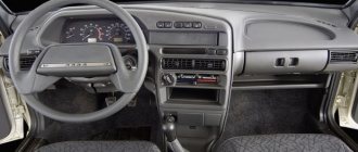
Where is
Control is carried out from the dashboard - using a switch. As a rule, it is placed on the left side of the steering column. The mechanism itself is located under the reflector. After pressing the button, the rod moves the headlight, which is mounted on hinges. The design is equipped with three connectors:
- for sensors;
- for power supply;
- for electronic adjustment of the reflector angle.
Connecting the electrical corrector BUK02-01 to a VAZ-2110
Installation of the BUK02-01 autocorrector on a VAZ-2110 (2111) car is carried out without modifications to standard places. In this case, you must first change the length and adjust the stroke of the rod depending on the specific model:
- VAZ-2110: stroke 2.0 with length 34.0.
- VAZ-2111: stroke 3.63 with length 34.0.
The stroke of the BUK02-01 rod is 7.0 with an offset of 38.8. Therefore, you will have to cut off the rod and reduce its stroke.
To cut the length of the rod, connect power to the drive so that the rod extends to its maximum stroke. First, we cut off part of the rod, then grind it off with a 9 mm file. After this, we glue the sawn-off part back with superglue.
To reduce the stroke of the rod, it is necessary to replace the 2.43 kOhm resistor with a 4.3 kOhm analogue. It is better to buy unframed resistors. They should be soldered directly to the switch. In this case there will be fewer wires.
The headlight electric corrector is adjusted in the “0” position, which meets the technical inspection requirements. Each division of the switch allows you to shift the axis of the light flux by 0.06 m, provided that the adjustment stand is installed at a distance of 1.2 m from the car headlights.
How to make automatic headlight leveling with your own hands
If it is almost impossible to make a dynamic auto-corrector with your own hands, then an electromechanical corrector (EMKF) can be made independently. Such a device can replace the hydraulic corrector on all models of domestic cars for which this is provided for by the design of the head optics.
The typical design of an electromechanical corrector consists of gear motors installed on each headlight and a control unit. The corresponding components can be purchased freely. Plus you will need a soldering iron, wires, fasteners, terminals, pads, casing, PVC tube or other insulating material.
Removing the standard system
Dismantling the standard hydraulic corrector begins with cutting through the pipelines and draining the liquid from them. They are usually located near the battery. This is followed by the operation of removing the main working cylinder. To do this, you will need a screwdriver, which you need to press the latch that secures the cylinder body. To pull it out, first turn the body counterclockwise until it stops and pull it towards you.
At the next stage of installing the automatic headlight leveler, you can go into the interior to remove the handle from the hydraulic leveler unit, held by a nut. And after the control unit is removed along with the pipelines, you can proceed to dismantling the rubber plug of the engine shield.
After this, all that remains is to prepare the electrical wiring by selecting wires of the required cross-section and length. From one edge of the wiring you need to solder the terminals to the control unit connection block. After this, the wires are laid through the hole in the engine shield where the pipeline was previously. Solder the other edge of the wires to the drive connection block. Typically, the automatic corrector comes with rubber protective covers for the pads. But in their absence, you can use sealant or heat-shrinkable tubes.
For power supply, there are two thick wires and 4 female terminals (one of them is wide, and the other three are narrow). Automatic headlight leveling works effectively when power is supplied and the low beam headlights are turned on. To do this you need to connect to:
- terminal No. 10;
- switch No. 64;
- rear fog light power supply.
The ground can be connected using the free terminal of the wire going to the ignition relay. Then install the drives in their standard location and secure with gaskets.
Xenon and LEDs
The century-long reign of the incandescent light bulb is coming to an end. The noble gases krypton and xenon help her “end her career” with dignity. The latter is considered one of the best fillers for incandescent lamps; with xenon, you can raise the temperature of the filament close to the melting point of tungsten and bring the light spectrum closer to that of the sun. But ordinary incandescent lamps filled with xenon are one thing. But “xenon” with a bright blue glow, which is used on expensive cars, is fundamentally different. In xenon gas-discharge lamps, it is not the red-hot filament that glows, but the gas itself—or rather, the electric arc that occurs between the electrodes during a gas discharge when a high-voltage voltage is applied.
For the first time such lamps (Bosch Litronic) were installed on the production BMW 750iL in 1991. Gas-discharge “xenon” is head and shoulders more efficient than the most advanced incandescent lamps; not 40% of the electricity is spent on useless heating, but only 7-8%. Accordingly, gas-discharge lamps consume less energy (35 W versus 55 W for halogen lamps) and shine twice as brightly (3200 lm versus 1500 lm). And since there is no filament, there is nothing to burn out; xenon gas-discharge lamps last much longer than conventional ones. But gas-discharge lamps are more complicated.
The main task is to ignite the gas discharge. To do this, from 12 “constant” volts of the on-board network, you need to get a short pulse of 25 kilovolts - and alternating current, with a frequency of up to 400 Hz! A special ignition module is used for this. Once the lamp is lit (it takes some time to warm up), the electronics reduce the voltage to 85 volts, enough to maintain the discharge. The complexity of the design and inertia during ignition limited the initial use of gas-discharge lamps to low beam mode. The distant light was the old fashioned way - “halogen”. The designers were able to combine low and high beams in one headlight six years later, and there are two ways to get bi-xenon. If a spotlight is used (like the one invented by Hella), then the switching of light modes is carried out by a screen located in the second focus of the ellipsoidal reflector: in low beam mode it cuts off some of the rays. At a distance, the screen hides and does not interfere with the light flow. And in the reflective type of headlights, the “double action” of the gas-discharge lamp is ensured by the mutual movement of the reflector and the light source. As a result, the light distribution changes along with the focal length. But according to the French company Valeo, by using separate gas-discharge lamps for low and high beams, you can achieve 40% better illumination than bi-xenon. True, not two, but four ignition modules are required; the expensive Volkswagen Phaeton W12 has such headlights.
However, the future of HID lamps is not nearly as bright as the light they emit. Experts predict the greatest success for LEDs. An LED is a semiconductor device that emits light when current passes. Until the early 90s, their automotive use was limited to display; the light output was too low. However, already in 1992, Hella equipped the three-ruble BMW Cabrio with a central brake light based on LEDs, and today they are increasingly used in rear lights as “dimensions” and brake lights. LEDs operate 0.2 seconds faster than traditional light bulbs, consume less energy (for brake lights - 10 W versus 21 W) and have an almost unlimited service life. But in order to replace bulbs with LEDs in headlights, a number of obstacles must be overcome. Firstly, even the best LEDs are still comparable in efficiency only to halogen lamps (light output is about 25 lumens per watt). At the same time, they are more expensive and require a special cooling system - after all, these are the same semiconductor devices as computer processors. But the developers assure that by 2008 the light output of diodes will reach 70 lm/W (for the current xenon it is 90 lm/W). So the first production LED headlights may appear in 2010. In the meantime, semiconductors are entrusted with secondary functions - for example, constant “daylight”, as Hella did by placing five LEDs in each headlight of the Audi A8 W12.
Lada Priora wiring block diagrams
1 – rear wiring harness block to the instrument panel wiring harness block; 2 – rear wiring harness block to additional wiring harness block 2 (left rear door); 3 – rear wiring harness block to side door wiring harness block (right front door); 4 – left side direction indicator; 5 – electrical package controller; 6 – right side direction indicator; 7 – interior lighting unit; 8 – handbrake warning lamp switch; 9 – left lamp of Lada Priora; 10 – right lamp; 11 – interior air temperature sensor; 12 – interior lamp switch in the driver’s door pillar; 13 – switch for the interior lighting in the pillar of the right front door; 14 – switch for the interior lighting in the pillar of the right rear door; 15 – interior light switch in the left rear door pillar; 16 – block of the rear wiring harness to the block of the wiring harness of the side doors 2 (left front door); 17 – rear wiring harness block to the additional wiring harness block (right rear door); 18 – blocks of the rear wiring harness to the rear right loudspeaker; 19 – blocks of the rear wiring harness to the rear left loudspeaker; 20 – cigarette lighter VAZ-2170; 21 – electric fuel pump module; 22, 23 – rear wiring harness blocks to instrument panel wiring harness blocks 2,3; 24 – trunk lighting; 25 – additional brake signal; 26 – trunk lock drive switch; 27 – interior lamp; 28 – rear wiring harness block to the front wiring harness block; 29 – left rear speed sensor; 30 – right rear speed sensor; 31 – sensor for automatic glass cleaning system (rain sensor); 32 – rain sensor sensitivity regulator; 33 – rear wiring harness block to instrument panel wiring harness block 4; 34 – block of the rear wiring harness to the block of the wiring harness of the parking system sensors; 35 – alarm unit for safe parking system; 36 – driver’s seat belt pretensioner; 37 – passenger seat belt pretensioner; 38 – rear wiring harness block to side door wiring harness block 3 (right front door); 39 – airbag control unit; 40 – parking system control unit; 41 – block of the rear wiring harness to the block of the rear additional wiring harness (tailgate); 42 – rear wiring harness block to rear additional wiring harness block 2 (tailgate); 43 – left seat heater; 44 – switch for electric seat heaters; 45 – right seat heater. 46 – rear wiring harness block to the parking system switch.
General information about car exterior lighting
The lighting system of a modern car combines many lighting devices. In addition to external lighting, the system also provides lighting for the interior, hood and even the luggage compartment (in some cars). Exterior lighting includes front-mounted low and high beam headlights, fog lights, turn signals, parking lights, brake lights, and license plate lights.
Headlights
Headlights located at the front provide good visibility of the road in conditions where there is no natural or artificial lighting or its insufficiency. These lights are also designed to make oncoming drivers aware of oncoming traffic. On most modern cars, the headlights have a single design, which includes a high and low beam headlight.
The low beam headlights are asymmetrical and provide better illumination on the sides of the road. High beam headlights, on the contrary, provide better illumination ahead, in the direction of travel, but it is not recommended to use it in the presence of oncoming traffic, since such light is very bright and can blind other drivers. Moreover, the use of high beams after other drivers have given special signals asking them to switch to low beams is considered a gross violation of traffic rules and can lead to an accident and administrative liability.
Turning lights
Turning lights are often built into the design along with low and high beam headlights. They are controlled by a lever located on the left side of the steering wheel. This lever, when moved, turns on one of the turn signals, then, when the steering wheel is turned, it fixes the position with a characteristic click and, after completing the maneuver, automatically returns to its original position. Turning lights are installed both at the front and rear of the car. And some vehicles also have these headlights on the sides (usually heavy-duty and route vehicles). Some redundant turn signals are installed in the rear of the rear view mirrors.
Side and daytime running lights
Side lights provide information about the vehicle's size to other drivers. They are located in both the front and rear headlights. The lights automatically turn on when the car is braking, as well as when the car engine is running at a stop or in a parking lot.
Daytime running lights significantly improve the visibility of the vehicle to other road users. They differ from standard ones in that they have more intense light.
Fog lights
Fog lights are optional and can be installed, at the request of the car owner, after purchasing the car. The light from these headlights is quite specific and defocused. When driving in fog, it seems to “cut through” the haze, illuminating various obstacles ahead, in the form of other vehicles, fallen trees, stones, etc. Fog lights are usually installed in front, below the main lighting fixtures.
Other lighting devices
Special external lighting devices are flashing beacons. These devices are installed on special service vehicles (Ministry of Internal Affairs, FSB, Ministry of Emergency Situations, emergency medical services, etc.) and are designed to attract the attention of other road users so that they are ready to give way to such a vehicle at the right time. These devices consist of two beacons rotating around their axis.
Beacons are usually blue and red. In addition to the above-mentioned vehicles, flashing beacons are also installed on vehicles transporting dangerous goods and drivers of special engineering vehicles.
But such beacons do not give them an advantage in traffic, but only inform drivers about the need to be careful
This is interesting: Where to buy a used Korean car?
A separate category of external lighting devices are retroreflective elements (warning triangle, cargo size indications, etc.). But their adjustment does not cause much difficulty, since they are always installed manually and temporarily.
Advantages of xenon lighting
Currently, halogen lighting devices are losing their relevance and, for obvious reasons, are being replaced by xenon headlights. They owe their name to the name of the gas - xenon, through which an electric discharge is passed, which leads to a glow. In addition to the high-pressure gas, the glass headlight bulb contains less than 1 mg of mercury and metal salts. What is one of the main advantages.
But besides this, it is worth highlighting three main key points that significantly distinguish xenon headlights from other analogues with the prefix more:
- Bright light.
- Safe lighting.
- Long resource.
The light from xenon headlights is significantly brighter than from halogen sources. And it doesn’t matter whether it’s far or near lighting. The light itself has a bluish tint, which brings it closer to daylight. This significantly improves visibility at night.
By installing auto-corrector for xenon headlights, you can notice an improvement in contrast and color depth, which leads to reduced eye strain. Moreover, their light does not blind oncoming drivers and is better reflected from the special paint on road signs.
But what is most important is the service life, which is much longer than that of halogen headlights (2 or even 3 times). Due to the absence of filaments, xenon lamps are more resistant to shock and vibration. And thanks to the use of ionized gas, electricity consumption is reduced by 25%. If you're lucky, the lamps can last the entire "life" of the car without replacement.
Step-by-step do-it-yourself headlight adjustment
When all the preparatory measures have been completed, you can begin to adjust the low and then high beam lighting.
Setting the low beam
After correct marking, turn on the headlights. First of all, the angle of inclination of the optical device is adjusted. The parameter must coincide with the horizontal line marked on the wall. To achieve the desired beam of light, rotate the adjusting screws, which are located on the back of the headlight in the engine compartment. The process occurs alternately, while one device is adjusted, the second is covered, for example, with cardboard. When placing the light beam slightly below the place where the centers of the optical instruments are marked, the procedure can be considered to have been performed correctly.
Setting the high beam
The distant lighting is adjusted separately from the near lighting, while the markings on the wall change slightly. The vertical surface must be flat and smooth, but the distance must be at least 10 m. The marking sequence is as follows:
- A fully equipped and fueled car is placed on a level area opposite a vertical surface on which the position of the centers of the headlights is marked. To record the real locations of these centers, we look for them by car. The resulting points are connected, and a horizontal line is also drawn 12 cm below the main one.
- After marking, the car is driven 10 m away, the light control is set to zero. The light beam, which is received from the head optics, must necessarily be located at the upper boundary on the bottom line under the main horizontal line.
Video: adjusting headlights using the example of a Ford Fusion
PTF adjustment
The adjustment is carried out by rotating the optical device vertically and horizontally, achieving the optimal angle of inclination. First loosen the bolts securing the fog lights to the bumper and perform the following steps:
- The car is installed on a flat surface at a distance of about 5–7 m from a vertical surface (for example, the wall of a house). The machine must be installed so that its axis is perpendicular to the plane on which the marking will be carried out.
- The tire pressure must be correct, and the car itself must be rocked from the side so that the suspension springs fall into place.
The adjustment process itself consists of the following steps:
- The distance between the center of the anti-fog optics and the base of the platform is measured.
- A horizontal line is marked on the wall, the level of which corresponds to the measurements taken.
- Turn on the low beam and make a mark on a vertical surface with the center of two beams.
- Turn off the low beam and turn on the fog lights.
- When the car is located 5 m from the surface with markings, the upper boundary of the light beam should be 10 cm below the height from the level of the horizontal platform. Anti-fog optics must be installed parallel to the longitudinal axis of the machine.
- The distance between the centers of the light beams should be 1200 mm.
- A line is drawn on the wall that divides the car into two halves.
- A strip is drawn that is 10 cm lower than the first.
- Measure the distance from the fog lamp to the ground and from the lamp to the center of the car.
- The resulting intersection of lines will be the center of the fog lights.
Video: how to adjust fog lights without a device
This is the scheme for adjusting the headlights and fog lights. After familiarizing yourself with the sequence of actions, you can perform the setup yourself. A correctly performed process increases the level of safety of the driver, passengers and other road users at night. From the above, we can conclude that periodically checking the efficiency of headlights is an important undertaking and neglecting this process is inappropriate.
To adjust the headlights yourself, you will need to prepare the car, find a vertical surface, a flat area for it and apply the markings correctly. All that remains is to adjust the optics with the adjusting screws, following a certain sequence of actions.
Source
PTF adjustment
Draw a horizontal line on the screen 50mm lower than the height from the fog lights to the ground. The light spot should be positioned so that the upper border on the screen is at the level of the drawn strip. The adjustment is made by rotating the adjusting screw, which is located next to the fog lamp.
Let us remind you that we previously told you how to independently replace the lamps in the Priora headlights, as well as install PTF.
The headlight leveler is a special device designed to maintain the installed axis of the headlights in a constant position. Thanks to the action of this device, the stability of the position of the optical axis is ensured when the load or driving conditions of the vehicle change.
Adjustment of the direction of the light flux is provided in all modern machines. The only exceptions are old cars. When the load on the vehicle changes, for example, when passengers get into the car or cargo is placed in the trunk, the beam of light from the headlights shifts upward. As a result, drivers in oncoming vehicles may be blinded.
To prevent accidents, car manufacturers install a special corrector. With its help, the driver can change the direction of the beam. But what to do when the headlight range control does not work? What could cause this device to malfunction, and what actions should I take?
Basic faults and repair options
If the headlight range control does not work in your car, there may be several reasons:
- The sensor has failed. In case of such a breakdown, a corresponding signal lights up on the car’s dashboard. The cause of the malfunction, as a rule, is a broken bracket, which can cause incorrect information to be transmitted from the controller to the control module.
- Deterioration of contact between the device and the system. This may be caused by acidification of the contact group, which reduces current conductivity. The result is that the headlight range control does not work.
- The tuning mechanism is broken. This problem is typical for domestic cars.
What types of headlight levelers are there, and how do they work?
The operating principle of headlight range control depends on the type of device. The following options are possible here:
- Manual regulator. Such units are mounted on cars from the budget price segment. The adjustment is made manually by the driver of the car, using a special wheel or switch mounted on the dashboard in the passenger compartment. Such a wheel has graphic or digital markings, thanks to which the position of the headlights and the exact luminous flux are set.
The principle of operation of the regulator is simple. When the wheel is turned, the system motor receives a command to adjust the position of the headlights, after which the gearbox sets the required position. The motor itself, made in the form of a worm gear, deserves special attention. Thanks to the action of the latter, the rotation of the electric motor is converted into a translational movement of the rod, which acts on the headlights of the car.
The electromechanical headlight range control is characterized by its simple design and ease of use. The only drawback is the fact that domestic car owners use the device’s capabilities in rare cases. As a result, other drivers experience inconvenience due to glare from headlights, which increases the risk of accidents.
- Automatic corrector. The advantage of such a device is the ability to regulate the position of the light beam automatically. To perform adjustment work, the person driving does not need to perform any actions - the system does everything itself. The setup process is carried out using a motor that receives information from the controller. The use of such a system is possible on all cars with xenon or halogen lamps installed in the headlights.
Headlight range control on a car
In the case of xenon, the use of a headlight range control is mandatory, because an incorrectly adjusted luminous flux can lead to blinding car owners on oncoming cars. As a result, road safety suffers.
Structurally, the device consists of a motor (actuator), a control module and controllers, which are used to measure ground clearance in various places of the car body.
The controller is mounted on the bottom of the car and works in conjunction with the suspension using traction. If the suspension stroke changes, force is transferred to the rotor using traction. Next, the rotor turns and changes the magnetic flux. The amount of change is calculated by the control module at a specific angle of rotation of the headlight. After this, the impulse is transmitted to the engine, which changes the position of the headlights.
The rotation module, when calculating the angle of change of position, is based only on several parameters - the angle of inclination of the machine, as well as the speed of its movement.
How to install the corrector yourself?
If, for any reason, the headlight range control does not work, it must be removed for repair or replaced. Against this background, the question arises of how to properly dismantle and subsequently install the device in place.
The algorithm of actions is as follows:
- Dismantle and remove the electromechanical type corrector.
- Enlarge the access hole to install the device. This work must be done if the dimensions of the device do not match the existing holes.
- Secure the new socket for attaching the headlight range control using sealant or glue.
- Mount the device by installing it in the prepared opening.
- Place the ground clearance controller, which should be mounted at the rear, on the bottom of the car.
The last step is to run the wire from the sensor to the device. To do this, it is necessary to use the existing tubes. The control module is installed anywhere, and then connected to the battery.
Video: Repairing headlight range control on a VAZ 2110
If the video doesn't show, refresh the page or click here
Video: Replacing headlight range control for VAZ 2110, 2111, 2112
If the video doesn't show, refresh the page or click here
Help guys! The headlight range control doesn't work! What could be the problem?
Guys, such a problem, the headlight range control does not work, I bought a new mus, and it still does not work. What could be the reason?
Who will watch Eurovision
by Adminrive · Published 05/19/2015
Good evening, is there anyone from Sevastopol?
by Adminrive · Published 05/28/2017
The arrows also need to be highlighted, etc.
by Adminrive · Published 10/01/2014
3 comments
- Comments 3
- Pingbacks 0
fuses, or a central control unit to help, look for a break...possibly a relay...
Andrey, what relay?
Andrey, look at the diagram, I haven’t come across it), there is either a fuse or a relay, and if everything is fine, then check the connection diagram
The article will be useful not only to owners of VAZ cars, which are equipped with an unreliable hydraulic corrector from the factory, but also to car enthusiasts who want to install xenon on their car with their own hands. In this case, installing an automatic headlight range control is mandatory.
We recommend that you familiarize yourself with the operating principle of the headlight range control. Understanding the device will help you understand exactly what parts are needed for the system to function properly. Perhaps, after reading the article about the DIY repair of the hydraulic corrector and electric corrector, the idea of finding a breakdown due to which the headlight range control does not work and restoring the standard system will seem more attractive to you.
Results
Automatic headlight leveling is required for cars equipped with standard lighting. This module will have a positive effect on the quality and direction of lighting, even if your car is loaded to the maximum. With autocorrector, you don’t have to worry about the fact that your car’s light can negatively affect the comfort of oncoming drivers. If the car is equipped with an auto-corrector, then you are guaranteed an easy and unhindered passage of the next technical inspection. Let the light in your car be correct.
Sources
- https://farainfo.ru/avtokorrektor-far-chto-eto-i-dlya-chego-printsip-rabotyi-avtokorrektora-far-i-vazhnyie-momentyi/
- https://mashinapro.ru/1800-korrektor-far.html
- https://InfoKuzov.ru/remont/korrektor-far
- https://ZnanieAvto.ru/svet-zvuk/korrektor-far-princip-raboty.html
- https://VipWash.ru/remont-far/avtokorrektor-far-svoimi-rukami
- https://TechAutoPort.ru/elektrooborudovanie-i-elektronika/sistema-osvescheniya/korrektor-far.html
- https://autodromo.ru/articles/korrektor-far-princip-deystviya-ustroystvo-nepoladki
- https://akki-carsh.ru/to/princip-raboty-korrektora-far.html
- https://fastmb.ru/autoremont/427-korrektor-far.html
- https://xenon-lampa.ru/cat-avtomobilnye-innovatsii/a-pravilnyj-svet-s-avtokorrektorom-far