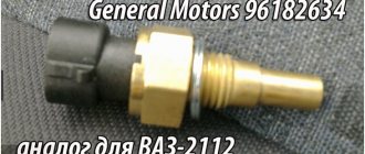
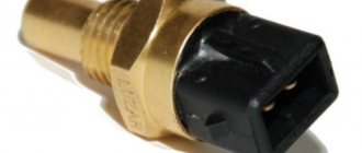
The main purpose of the temperature sensor on the VAZ 2106 is to control the heating of antifreeze and other coolant used as a coolant in the cooling system. Information about the antifreeze temperature is displayed on a special indicator in the cabin.
It is important to periodically monitor the condition of the temperature sensor - overheating of the engine will lead to the need for major repairs.
Connection diagram for temperature sensor VAZ 2106
VAZ 2108, 2109, 21099 cars have a dial gauge for the coolant temperature in the instrument panel. Connection diagram for the coolant temperature indicator sensor in the cooling system of VAZ 2108, 2109, 21099 cars up to 1998. with mounting block 17.3722 and “low” instrument panel
Connection diagram for the coolant temperature indicator sensor in the cooling system of VAZ 2108, 2109, 21099 cars after 1998. with mounting block 2114 and “high” instrument panel
Notes and additions
— The cooling system of carburetor engines of VAZ 2108, 2109, 21099 cars is equipped with another temperature sensor - the cooling system fan switch sensor (TM-108). It is installed in the radiator tank and its signal turns on the radiator fan.
— The cooling system of an injection engine also has a coolant temperature indicator sensor. The control function of turning on the fan is carried out by the control unit (ECU) based on a signal from the coolant temperature sensor (DTOZH), installed in the pipe near the thermostat.
More articles on the engine cooling system of VAZ 2108, 2109, 21099 cars
Generator connection diagram: 1 – battery; 2 – generator; 3 – voltage regulator; 4 – ignition switch (lock); 5 – fuse block; 6 – battery charge indicator lamp; 7 – battery charge warning lamp relay
Starter connection diagram: 1 – starter; 2 – battery; 3 – generator; 4 – ignition switch (lock); P1 – relay pull-in coil; P2 – relay holding coil
Diagram of the contact ignition system: 1 – spark plugs; 2 – ignition distributor; 3 – ignition coil; 4 – ignition switch (lock); 5 – generator; 6 – battery
Diagram of a contactless ignition system: 1 – battery; 2 – generator; 3 – ignition switch (lock); 4 – ignition coil; 5 – switch; 6 – ignition distributor sensor; 7 – spark plugs
Connection diagram of the carburetor solenoid valve control system 21053-1107010: 1 – carburetor limit switch; 2 – solenoid valve; 3 – control unit; 4 – ignition coil; 5 – switch; 6 – ignition switch (lock)
Diagram of the alarm system and direction indicators: 1 – direction indicator lamps in the front lights; 2 – battery; 3 – generator; 4 – side direction indicators; 5 – main fuse block; 6 – additional fuse block; 7 – ignition switch (lock); 8 – alarm switch; 9 – direction indicator switch; 10 – relay-interrupter for direction indicators and hazard warning lights; 11 – speedometer with indicator lamp for turning on the direction indicators; 12 – direction indicator lamps in the rear lights
Scheme for switching on sound signals: 1 – sound signals; 2 – relay for turning on sound signals; 3 – sound signal switch; 4 – fuse block; 5 – generator; 6 – battery
Heater electric motor switching diagram: 1 – heater electric motor; 2 – additional resistor; 3 – heater motor switch; 4 – fuse block; 5 – ignition switch (lock); 6 – generator; 7 – battery
Electrical diagram of the VAZ-2106 car: 1 – side direction indicators; 2 – sidelights; 3 – external headlights; 4 – internal headlights; 5 – sound signals; 6 – electric motor of the engine cooling system fan; 7 – fan motor activation sensor; 8 – relay for turning on sound signals; 9 – relay for turning on the fan electric motor; 10 – voltage regulator; 11 – ignition coil; 12 – windshield washer electric motor; 13 – sensor of insufficient brake fluid level; 14 – ignition distributor; 15 – windshield wiper motor; 16 – spark plugs; 17 – oil pressure warning lamp sensor; 18 – oil pressure indicator sensor; 19 – coolant temperature indicator sensor; 20 – engine compartment lamp; 21 – carburetor solenoid valve; 22 – generator; 23 – starter; 24 – battery; 25 – battery charge warning lamp relay; 26 – relay for turning on low beam headlights; 27 – relay for turning on the high beam headlights; 28 – windshield wiper relay; 29 – additional fuse block; 30 – main fuse block; 31 – reverse light switch; 32 – parking brake warning lamp switch; 33 – plug socket of a portable lamp; 34 – relay-interrupter for direction indicators and hazard warning lights; 35 – heater electric motor; 36 – brake signal switch; 37 – rear window heating relay [Installed on some cars.]; 38 – additional resistor of the heater electric motor; 39 – trunk lighting lamp; 40 – external lighting switch; 41 – rear window heating switch*; 42 – ignition switch (lock); 43 – headlight switch; 44 – direction indicator switch; 45 – horn switch;
46 – wiper switch; 47 – windshield washer switch; 48 – instrument lighting switch; 49 – alarm switch; 50 – cigarette lighter; 51 – heater switch; 52 – control lamp for the fluid level in the hydraulic brake reservoir; 53 – switches for warning lights of open front doors*; 54 – alarm lights for open front doors*; 55 – lamp switches located in the front doors; 56 – fuel level indicator with reserve indicator lamp; 57 – coolant temperature indicator; 58 – oil pressure gauge with warning lamp; 59 – tachometer; 60 – indicator lamp for turning on the parking brake; 61 – battery charge indicator lamp; 62 – control lamp for the carburetor air damper; 63 – speedometer; 64 – control lamp for turning on external lighting; 65 – control lamp for turning on the direction indicators; 66 – control lamp for turning on the high beam headlights; 67 – relay-interrupter for the warning lamp for turning on the parking brake; 68 – switch for the carburetor air damper warning lamp; 69 – hours; 70 – lamp switches located in the rear doors; 71 – interior lamps; 72 – rear window heating element*; 73 – trunk lighting lamp; 74 – sensor for level indicator and fuel reserve; 75 – rear lights; 76 – license plate lights
The main purpose of the temperature sensor on the VAZ 2106 is to control the heating of antifreeze and other coolant used as a coolant in the cooling system. Information about the antifreeze temperature is displayed on a special indicator in the cabin.
It is important to periodically monitor the condition of the temperature sensor - overheating of the engine will lead to the need for major repairs.
Modifications
Switching diagram for electric windows of the front doors
1 – main fuse block; 2 – relay for turning on electric windows; 3 – left door power window switch; 4 – right door power window switch; 5 – gear motor for the right door electric window; 6 – gear motor for electric window lifter of the left door; 7 – additional fuse block; 8 – ignition switch; A – to terminal “30” of the generator; B – to the instrument lighting switch; B – conventional numbering of plugs in the gear motor block.
Carburetor solenoid valve control circuit
1 – ignition switch; 2 – generator; 3 – battery; 4 – ignition coil; 5 – switch; 6 – control unit; 7 – carburetor solenoid valve; 8 – carburetor limit switch.
Engine cooling fan motor
1 – generator; 2 – battery; 3 – ignition switch; 4 – main fuse block; 5 – electric fan activation relay, 6 – electric fan activation sensor; 7 – electric fan; 8 – additional fuse block
Purpose
So, what functions does the sensor perform? This element is necessary to control the coolant temperature, so that in case of overheating the driver can react to the situation in time. Information from the sensor is displayed on the instrument panel. The driver can observe how hot or cold the coolant is in the engine system. In this car, the VAZ-2106 temperature sensor no longer performs any functions.
How to replace an element?
To replace the VAZ-2106 engine temperature sensor, it is enough to cool the engine if it was previously heated. In the process, you will have to unscrew the element from the cylinder head cooling jacket, and you can get burned by the hot liquid. The sensor has an M14 thread. In order to unscrew it, you will need a 19mm wrench. The faulty element is unscrewed, and a new one is screwed in its place. In some cars, it is recommended to drain the coolant a little before replacing it.
You can replace the sensor with any one that is sold in the store and fits the thread in the cylinder head. The main thing is that the contacts on the element are similar to the plug in the car wiring. Then everything will connect and work without any problems.
Signs of sensor failure
It is generally accepted that the temperature sensor on the VAZ 2106 is a reliable device, since its design is very simple. However, problems may occur. As a rule, all problems are associated with changes in the resistance of the thermistor. Due to the changed resistance, the operation of the electronic unit is disrupted, which receives erroneous data and cannot correctly influence the preparation of the fuel mixture. You can understand that the sensor is faulty by the following signs:
- severe oxidation of the sensor housing. As mentioned above, sensor housings are usually made of brass. This is a copper based alloy. If the driver, having unscrewed the sensor from its socket, found a green coating on it, then the cause of the breakdown has been found;
With all of the above problems, the driver will have to change the temperature sensor. It cannot be repaired, so going to an auto parts store and replacing the device is the only rational option. The price of sensors for a VAZ 2106 starts from 200 rubles.
Where is
Over the entire production period of the car of the model in question, quite a lot of different modifications were produced. But it is worth noting: on most VAZ 2106 cars, sensors are installed in special sockets on the cylinder blocks.
The latest models of the VAZ 2106 car were equipped with specially designed thermostats. A temperature sensor monitoring the state of antifreeze was located in them. But such designs are relatively rare.
In the latter case, the sensor is located next to the pipe - it is through it that hot antifreeze enters the radiator. Thanks to this arrangement, it is possible to obtain the most accurate data. The sensor itself, due to the simplicity of its design, fails relatively rarely. Problems arise during long-term use. Gradually the thermistor changes its resistance. As a result, the electronic control unit receives incorrect data.
Main signs of sensor malfunction:
the presence of a large amount of oxides on the surface of the case - if there is a green coating (brass oxide), the cause of the breakdown lies precisely in it;
- a significant increase in gasoline consumption - incorrect data transmitted to the electronic control unit often leads to an increase in the amount of fuel supplied when there is no need for it;
- problems with the engine - it is difficult to start it when cold, the engine suddenly stalls, and idles unstable.
There is no point in repairing the temperature sensor on a VAZ 2106. If a breakdown occurs, it should simply be replaced with a new one. Its cost is from 200 rubles.
The central part of the electrical equipment diagram of the VAZ-2106
The central piece of the circuit mainly consists of light on/off switches and switches for supplying current to the system.
The main wiring elements are indicated by the following numbers:
- Kit with main fuse block (30);
- Light switches in the car's reversing headlights (31), operation of warning lamps when the hand brake is applied (32);
- Types of plug sockets for portable lamps (33);
- Equipment for operating the turn signal and hazard signal (34);
- Design of the electric motor of the stove (35) and the terminal for turning off the brake light (36);
- Current supply relay for heating the rear window (37);
Tip: depending on the modification and year of manufacture of the VAZ-2106, the type of relay and its position in the network may change. To repair this spare part, it is best to use the diagrams that come with the machine.
- Set of resistors for the VAZ 2106 heater electric motor (38);
- Wiring to the light bulb in the glove box (39);
- List of switches for exterior lights (40), heating the rear surface of the glass (41), as well as the ignition system (42);
- A set of switches from low to high beam (43), a windshield wiper (46) and a car turn indicator arrow (44);
- Special types of vehicle horn switches (45), universal windshield washer switches (47) and dashboard light and emergency signal controls.
Pinout of the dashboard of VAZ2105, 2106, 2107
Old panel (with oil pressure gauge)
In addition to the presence of an oil pressure indicator, it is worth noting that this instrument panel does not have an air damper indicator lamp (choke), and the emergency oil pressure lamp is located next to the pressure indicator. Because of this, it contains lamps for low brake fluid levels and fog lamps.
White 6-terminal block X1:
- Gasoline level sensor
- Turn signal indicator lamp
- Battery charge sensor (voltmeter -)
- Gasoline level warning lamp
- Overall plus (+)
- Battery charge sensor (voltmeter +)
White 8 terminal block X2:
- Fog lamp warning lamp
- High beam warning lamp
- Dimensions indicator lamp
- Empty
- Battery charge indicator lamp
- Brake fluid level warning lamp
- Empty
- Parking brake warning lamp
Orange 6-terminal block X3:
- General minus (-)
- Tachometer VAZ
- Instrument lighting
- Oil pressure sensor
- Oil pressure warning lamp
- Coolant temperature sensor
New instrument panel (with econometer)
Here, everything is the other way around - there is no oil pressure indicator (instead there is an econometer), instead of a brake fluid level lamp there is a suction lamp (or an engine management system lamp on injectors), and instead of a fog lamp lamp there is an oil pressure lamp.
White 6-terminal block X1:
- Gasoline level sensor
- Turn signal indicator lamp
- Battery charge sensor (voltmeter -)
- Gasoline level warning lamp
- Overall plus (+)
- Battery charge sensor (voltmeter +)
White 8 terminal block X2:
- Dimensions indicator lamp
- High beam warning lamp
- Oil pressure warning lamp
- Empty, but there is a terminal in the wiring that goes to the brake fluid level sensor
- Battery charge indicator lamp
- Indicator lamp for the air damper (choke) or engine control unit for injectors
- Empty
- Parking brake warning lamp (handbrake)
Orange 6-terminal block X3:
- General minus (-)
- Tachometer (if this contact is empty, then the tachometer is on pin #4)
- Instrument lighting
- Empty, and if not empty - to the tachometer
- Empty
- Coolant temperature sensor
Second connection diagram option
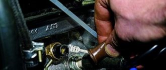
Temperature sensor replacement process
It is imperative to replace it with a cold one. Be sure to disconnect the terminals from the battery. To replace you will need:
- open-end wrench 21;
- new antifreeze sensor for VAZ 2106.
- The protective plastic is carefully removed - using a 21 key, the sensor is carefully unscrewed from its seat;
- Without unscrewing the old sensor completely, you should take the new one in your other hand;
- then the part is unscrewed completely, after which the hole is plugged with a finger;
- the finger is removed and a new sensor is screwed in.
All manipulations must be performed as quickly as possible. Otherwise, antifreeze, antifreeze or other coolant will simply leak out. The replacement process does not take much time. It is only important to prepare in advance and take precautions.
Replacing the temperature sensor Lada 2106 (VAZ 2106)
Posts tagged "temperature sensor"
Removing the radiator from a VAZ 2106 and checking it for leaks
03/28/2009 | Author: admin
In order to remove the radiator of the cooling system from a VAZ 2106 (VAZ 21061, VAZ 21063, VAZ 21065) car, you need to perform the following fairly simple manipulations:
— first, you need to drain the coolant (antifreeze) from the radiator and cylinder block, to do this, remove the drain plugs from the lower radiator tank and the plug on the cylinder block, while not forgetting to open the cabin heater tap and remove the plug from the filler neck;
— next, disconnect all the hoses connected to the radiator, as well as the connection wires for the electric motor of the radiator cooling fan and its temperature sensor;
- Immediately you need to unscrew the bolts and remove the fan casing along with the electric motor;
- and the final stage will be to disconnect the radiator itself from the body by unscrewing the mounting bolts. Now you can remove the VAZ 2106 radiator from the engine compartment.
After successfully removing the radiator, it is recommended to check it for leaks to avoid coolant leakage. Leak tightness is usually checked in a bath of water. To do this, you need to plug all the radiator pipes and supply air to it at a pressure of approximately 0.1 MPa and lower it into water. If air etching occurs (bubbles will come from the radiator), then the radiator is NOT sealed.
In this case, if the damage is minor, then it will be enough to solder the damaged area with soft solder, but if the damage is significant, then nothing can be done, you just need to replace the radiator with a new one.
Coolant temperature gauge
The temperature indicator needle is constantly at the beginning of the scale
The temperature gauge sensor or wire is faulty. connecting the sensor to the temperature indicator. as well as a coolant temperature indicator
With the ignition on, disconnect the wire from the sensor and connect the wire tip to ground. If the arrow deviates. The sensor is faulty and should be replaced. If the arrow does not deviate. Remove the instrument panel and, with the ignition on, connect plug V of the indicator to ground. The deviation of the arrow in this case will indicate the serviceability of the device and damage to the wire. connecting the sensor to the pointer. If the arrow does not deviate. replace temperature gauge
The sensor is faulty. The wire. suitable for the sensor. closed to ground. Damaged temperature gauge
With the ignition on, disconnect the sender wire. If the sensor is faulty, the arrow should return to 0. If the arrow remains in the red zone. either the wire has a short to ground. or the temperature gauge is damaged. Check the serviceability of the pointer. by disconnecting the green wire from it. going to the sensor. When the ignition is on, the needle should be at the beginning of the scale at 0
Removing the instrument panel
To remove the shield 2 from the instrument panel 1 to replace a faulty device or a burnt-out lamp, press the brackets 3 with the firmware 4 through special holes in the lower part of the instrument panel, then disconnect the plug connections of the instruments and disconnect the flexible drive shaft from the speedometer.
When removing the instrument panel, pay attention to how the flexible shaft of the speedometer drive was routed, and when installing the panel, place the flexible shaft along the same route so that there is no strong bending of the shaft (so that the bending radii are more than 100 mm).
Coolant temperature gauge UK-193. Used with sensor TM-106. With a sensor resistance of 640-1320 Ohms, the needle should be at the beginning of the scale, with 77-89 Ohms - at the beginning of the red zone, and with 40-50 Ohms, it should deviate to the end of the red zone of the scale.
When the pointer needle is constantly at the beginning of the scale, then with the ignition on, disconnect the wire from the pointer sensor and connect the tip of the wire to ground. If the arrow deviates, then the sensor is faulty and is replaced, and if it does not deviate, remove the instrument panel and, with the ignition on, connect the indicator plug “V” to ground. The deviation of the arrow in this case will indicate the serviceability of the device and damage to the wire connecting the sensor to the pointer.
If the arrow does not deviate, replace the temperature gauge. When the pointer needle is constantly in the red zone, then with the ignition on, disconnect the wire from the sensor. If the sensor malfunctions, the needle should return to the beginning of the scale. If it remains in the red zone, then either the wire is shorted to ground or the device is damaged. The serviceability of the device is checked by disconnecting the green wire (going to the sensor) from the indicator. When the ignition is on, the needle should be at the beginning of the scale.
Fuel level indicator UB-193. Used in conjunction with the BM-150 sensor installed in the fuel tank. This sensor also turns on the fuel reserve warning lamp if there are 4-6.5 liters of gasoline left in the tank. With a sensor resistance of 285-335 Ohms, the needle should be at the beginning of the scale, with a resistance of 100-135 Ohms - in the middle of the scale, and with a sensor resistance of 7-25 Ohms, it should deviate towards the end of the scale.
The verification procedure is similar to that described above. When the pointer needle is constantly at the beginning of the scale and does not deviate after the tip of the wire disconnected from the “T” plug of the sensor is connected to ground, then the device is checked. To do this, remove the instrument panel and, with the ignition on, connect the indicator plug “S” to ground. If the device is working properly, the needle should deflect to the end of the scale. When the pointer arrow is constantly against o, the serviceability of the device is checked by disconnecting the pink wire from the pointer (going to the “T” plug of the sensor). In this case, with a working device, when the ignition is turned on, the arrow should be against the o.
Oil pressure indicator UK-194. Used in conjunction with sensor type MM393A. With a resistance of 285-335 Ohms, the pointer needle should be against o, with a resistance of 100-135 Ohms - in the middle of the scale, and with a resistance of 0-25 Ohms - at the end of the scale. The device has a warning lamp for insufficient oil pressure, which is turned on by the MM-120 sensor. The sensor contacts should close and open at a pressure of 20-60 kPa.
The method for checking the device is similar to that described above. When troubleshooting, connect the indicator plug “H” to ground or disconnect the gray wire with black stripes going to the pressure sensor from it.
Tachometer TX-193. The operating principle of the tachometer is based on measuring the frequency of voltage pulses in the primary circuit of the engine ignition system.
The tachometer is checked on a stand that simulates the car’s ignition system. By connecting the tachometer to the stand circuit in the same way as on a car, set the voltage in the primary circuit to 14 V and the gap in the stand spark gap to 7 mm. Rotate the ignition distributor shaft at such a speed that the tachometer needle reaches one of the scale divisions. At this point, check that the distributor shaft rotation speed is within the following limits:
Speedometer SP-193. It consists of a dial indicator of the vehicle speed (km/h), a final distance meter (km) traveled by the vehicle, and a daily vehicle mileage meter. The speedometer is checked by comparing its readings with the standard ones. The verification data is given below.
Top of page
Methods for checking temperature sensors
If the driver wants to make sure that the cause of problems with the car is the antifreeze sensor, then he will have to carry out a simple checking procedure. But before you start, you need to make sure the integrity of the car wiring. As mentioned above, for the sensor to work normally, it must be continuously supplied with a voltage of 5 volts. To make sure that the supplied voltage does not deviate from this value, you should start the car, and then remove the wires from the sensor and connect them to a multimeter. If the device clearly shows 5 volts, then there are no problems with the wiring and you can begin to examine the sensor itself. There are two verification methods. Let's list them.
Hot water test
The sequence of actions in this option is simple.
- The sensor is placed in a pan of cold water. An electronic thermometer is also placed there (it is much more convenient than a regular one, because the measured temperatures will be quite high).
The thermometer and sensor are placed in a container of water
Table: temperatures and corresponding resistances, characteristic of serviceable VAZ 2106 sensors
Checking without an electronic thermometer
This method of checking the sensor is simpler than the previous one, but less accurate. It is based on the fact that the temperature of boiling water reaches one hundred degrees and does not rise higher. Therefore, this temperature can be used as a reference point and find out what the sensor resistance will be at one hundred degrees. The sensor is connected to a multimeter switched to resistance measurement mode, and then immersed in boiling water. However, you should not expect the multimeter to show a resistance of 177 ohms, which corresponds to a temperature of one hundred degrees. The fact is that the temperature of water constantly decreases during the boiling process and averages 94–96 °C. Therefore, the resistance on the multimeter will vary from 195 to 210 ohms. And if the numbers produced by the multimeter differ from the above by more than 10%, the sensor is faulty and it’s time to change it.
Video “Solving the idle problem”
How to rid yourself of the problem XX - watch the video (the author of the video is Nail Poroshin).
Like the rest of the sensors and indicators on the instrument panel of the VAZ 2106, the temperature indicator is very easy to remove and this operation will not take you more than 10 minutes of time. You don’t need any tools, but in a pinch, pliers can help.
To begin, remove the instrument panel trim by first pulling it off the clips and pulling it towards you to the side. The result of this action should look something like the one shown in the photo below:
As you can already see, the temperature indicator will be the second one on the left edge of the instrument panel. You need to find the plug with the wires connected to it and disconnect it:
Now, using your hand or using pliers, unscrew the “twist” that secures the pressure plate:
Then you can remove the plate from the temperature gauge pin:
And you can easily remove the device from the outside, as shown in the picture below:
The procedure for replacing this device is very simple, since everything is done strictly in the reverse order. The price of a new sensor is about 300 rubles.
Any driver should know the engine temperature of his car. This also applies to owners of the VAZ 2106. Ignorance about the critical temperature of the engine can result in it overheating and jamming. The engine temperature on the VAZ 2106 is monitored by a special sensor. It, like any other device, sometimes fails. Fortunately, it is quite possible to change the temperature sensor yourself. Let's figure out how this is done.
Oil pressure
On “sixes” and other classic models, a VAZ 2106 oil pressure sensor of type Mm393A is installed. The pressure indicator works on the principle of converting this parameter, which is created in the lubrication system, into resistance. The oil pressure sensor is installed in the engine cylinder block. A regulator is also installed here, which turns on the oil pressure light.
This element is triggered as a result of the closing and opening of contacts at a particular level of pressure in the system. The corresponding indicator on the control panel may light up if the characteristics are violated, namely, if there is little liquid in the system.
Designation of part elements
How to check the controller? You can check the engine fluid pressure sensor by removing the regulator from its installation location. After removal, you should turn the starter; you do not need to start the power unit. If everything is fine with the supply of consumables, then you need to change the regulator. You can tell about the oil supply by the splashing of liquid from the controller seat.
Tips and tricks
Having figured out how to check the fan switch sensor, it would be useful to learn about some features that can sometimes be present when performing such work.
- The most effective express method for diagnosing sensors of this type is to short-circuit its contacts with a screwdriver.
- Sometimes this switching element may be in a permanently closed state, which causes the fan to constantly operate. In this case, the product should also be checked using a light bulb, which will glow regardless of the temperature of the part.
- If the sensor turns on randomly from time to time, it will also need to be replaced.
- Replacing the air blower with a known-good element allows you to quickly eliminate the inoperability of the cooling fan.
All work on diagnosing and replacing the VAZ 2106 fan switch sensor can be carried out independently in a garage, so if you have a similar problem, it is absolutely not necessary to contact professional auto repairmen.
Connection
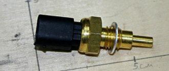
Connecting the VAZ-2106 temperature sensor is extremely simple. There is a single contact on the tail part of the DTOZH, screwed into the cylinder block. It is connected to the wire going to the dashboard. It has a corresponding terminal. To connect, just connect the terminal to the contact on the sensor, and then the dashboard will show the heating of the coolant, and therefore the engine temperature.
Device
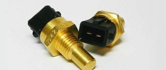
If we consider the device, there are two types of temperature sensors. The first is a thermistor. This is a thermal resistor whose resistance changes as the temperature increases or decreases. The thermistor is located inside a threaded metal housing. There is a plastic tail part on the body. Contacts are installed at the rear. There is one contact (positive) on the tail section. It goes to the dashboard. The role of the second contact is performed by the housing - it is connected to the total mass.
The second type of sensor is a special contactor with a bimetallic strip inside. The latter, depending on the heating of the antifreeze, closes or opens.
The first temperature sensor of the VAZ-2106 is used only to display data on the heating of antifreeze in the cooling system. As the temperature rises, the resistance of the sensor changes. A certain voltage is applied to the instrument scale. The device is installed in the engine cylinder block in the channels of the cooling system.
The second temperature sensor is designed a little differently. It also reacts to the temperature of antifreeze or antifreeze, but is designed to turn on the electric fan on the radiator. This sensor is installed on the radiator.
Principle of operation
For normal operation of the VAZ-2106 cooling temperature sensor, a voltage of 5 V is required. Since the thermistor has a negative temperature coefficient, as the antifreeze heats up, the resistance on the sensor will drop. Accordingly, the tension will decrease. The instrument panel determines the temperature based on the level of voltage drop.
In different VAZ models, the sensor can be located in different places - in the cylinder head, in the thermostat housing or on its body. The element must be placed in the area of the outlet hose, which is needed for the passage of fluid into the radiator. In the VAZ-2106, DTOZH can be found in the cylinder head.
How to check?
Since the VAZ-2106 coolant temperature sensor is extremely simple, the methods for diagnosing it are extremely simple. But before diagnosing the element, you should inspect the wiring and its integrity. You can also check whether voltage is coming to the sensor.
The most accurate way to check functionality is to measure the resistance using a multimeter. But during the measurement process, the element will have to be boiled in water. As the temperature changes, the resistance of the sensor will change. But since in the VAZ-2106 the DTOZH does not affect anything, it is easier to simply replace the faulty element. Moreover, its price is not higher than two hundred rubles.
VAZ cooling fan connection diagram
All the main electrical circuits and modifications for connecting the liquid cooling fan (CO) in VAZ cars of various models are provided. What is the essence of VO’s work? An electric motor with an impeller on a shaft is installed inside a rectangular metal frame, with which it is attached to the back of the radiator. When voltage (12 V) is applied to the contacts of the drive, it begins to work, rotating the blades and creating a directed stream of air, which, in fact, cools the antifreeze or antifreeze.
vote
Article rating