In my last post I said that I bought a new battery, but the car still wouldn’t start.
But I didn’t get the expected result because there was no pressure in the fuel rail. I immediately removed the fuel pump and replaced it.
Pekar became Siemens.
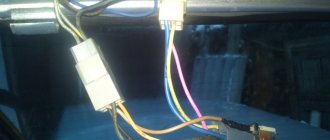
During assembly I noticed a burnt connector.
In general, it didn’t start.
The next day I got into the car and tried to start it and it started O_o. I even managed to rejoice. True, not for long.
I was about to assemble the seat, the car was idling. I see smoke coming from the connector! I quickly plugged and unhooked the connector and only then got scared...
All this rigmarole prompted me to change the connectors (which should have been done right away)
To be honest, I thought that I wouldn’t find all the connectors, but no, the basins have everything, literally everything. I was very surprised that they were found without problems.
How does the electrical circuit of the VAZ 2115 (injector, 8 valves) turn on and work? Once you understand it and understand the principle of operation, you can effectively drive your car and perform minor repairs.
Design Features
A novice car enthusiast is recommended to study the operation of an injection engine. The injector includes a system that injects gasoline. After familiarizing yourself with the device, you won’t have to contact a service center for minor problems, but rather fix them at home yourself. The fuel supply is considered distributional, because gasoline is injected into each cylinder using a specific injector.
The VAZ 2115 is based on the VAZ 21099 model. In the new car, unlike the previous one, the shape of the hood, rear and front bumpers, a new configuration of the front wings, as well as improved aerodynamics of the body have changed. A spoiler was placed on the trunk lid - a wing. The exterior decoration was decorated with plastic elements, since metal ones were corroded by corrosion. For added safety, the model was supplemented with a brake signal and rear lighting.
Thanks to the electronically controlled injection power unit located under the hood, the electrical circuit of the VAZ 2115 differs significantly from the 99 modification.
The supporting structure of the car body is welded, metal, integral. The drive is front transverse. It has a 5-speed gearbox and the front wheels are connected to the drive. The engine has a capacity of 1.5 liters and is a four-cylinder, petrol, four-stroke and in-line. Distributive fuel injection systems are controlled electronically.
Under the rear seats, behind the bottom, there is a fuel tank. Gasoline is supplied from the gasoline pump located in it. The pressure level in it should not fall below 3.2 bar.
Hidden interior sub-cabinet wiring connects the located equipment. The mounting block is placed in the engine compartment. It consists of powerful consumers: wipers, high beam headlights, starter. All of them are connected to the on-board network using an intermediate relay.
Ignition system and starter connection diagram
The VAZ wiring diagram includes a VAZ ignition system module, consisting of two high-voltage transformers and two electronic control units. They are in a durable plastic case, from which 4 high voltage wires are removed. They have a connection that creates a synchronous passage of a spark entering the cylinders of the power plant.
The VAZ 2114 ignition module consists of a two-spark coil and is of the block type. The ignition switch turns on a relay that sends a signal to the controller. The latter is the control element of the injection system for starting the fuel pump. It is connected to the cleaning filter with a flexible hose. After this, gasoline is supplied to the fuel rail, from which the fuel is supplied to the injectors.
The pinout of the VAZ ignition switch is in itself. It has an anti-theft device. When the lock socket illumination is on and the engine is running, the anti-theft locking device blocks the VAZ starter from re-engaging.
The starter connection diagram consists of:
- the starter itself;
- generator;
- rechargeable batteries;
- ignition switch;
- two relays.
The engine for the VAZ 2114 is also a four-stroke injector, in-line with an 8-valve unit. Its camshaft is at the top. Operates on gasoline fuel and is equipped with 4 cylinders. It is cooled with a special liquid solution. The engine compartment contains a motor located perpendicular to the direction of movement.
The VAZ wiring diagram has electronics that control the injection system. It operates at low voltage, so it can be damaged very easily by electrostatic discharge. To prevent this from happening, do not touch the circuit elements on the boards or the ECU plugs.
How to check the performance of the fuel pump
Often, for those problems for which the car owner blames the fuel pump, other elements of the fuel system are to blame. To establish whether a fuel pump has failed, you will need to know the reasons why it might break.
Causes of fuel pump malfunctions
Most often, the device may fail while the vehicle is moving. The gas pump may simply refuse to pump fuel from the tank to the engine, or a leak may form, causing the device to malfunction. If the power supply is interrupted, the pump stops working completely.
The main causes of fuel pump malfunctions include the following:
lack of tightness in the pump itself (leakage);
damage to membrane surfaces;
the resource of the pump motor has been used up;
wiring or relay problems;
dirt and debris in the fuel tank, which, along with gasoline, enter the pump.
As you can see, there can be many reasons for a fuel pump to fail.
Dirt deposits on the filter mesh are a common cause of fuel pump malfunctions.
Symptoms of a problem
There are only four main signs by which you can diagnose malfunctions in the fuel pump without special tools:
The car simply won't start. Of course, the engine may not function for a number of other reasons, however, first of all, you will need to check the functionality of the fuel pump itself.
After the car starts, the characteristic buzzing of the fuel pump is inaudible. The whirring noise should be clearly audible in the rear of the cabin, as the fuel pump is located under the rear seats.
Recently, interruptions in the operation of the power unit have begun to be observed: the engine does not start the first time, while driving you can hear the engine straining.
The car starts to jerk when driving at low speed.
Electrical circuit design of VAZ 2115
The VAZ wiring diagram is a single-wire circuit, which supplies the positive pole from the battery to the remaining elements of the circuit, and the negative pole is the housing.
The electrical circuit of the VAZ is protected from current surges in the form of fuses with fuse links. They were placed under the hood.
Fuses provide reliable protection for such expensive equipment as:
- the circuit in which the ignition switch is included;
- battery charging circuit;
- generator circuit and starter.
The VAZ electrical circuit includes relays that connect:
- headlight cleaners;
- emergency alarm;
- direction indicators;
- windshield cleaners;
- monitoring the serviceability of light bulbs;
- electric lifts;
- electric heated rear windows;
- horn;
- driving lights;
- low beam headlights.
The VAZ wiring diagram is made with wires of a certain color, which are designated by letters. A wiring harness of a certain color is secured with blocks.
The injection engine is controlled by a system that consists of a control unit - ECU - and sensors. The control unit occupies a central place in the fuel supply system. It has a second name - controller. It processes information received from sensors and controls systems that neutralize the toxicity of waste products and the performance of the machine.
There is a constant relationship between these elements - the controller and the sensors, which ensures uninterrupted operation of the drive.
The VAZ wiring diagram includes sensors with the following functions:
- fixing the position of the crankshaft: interacting with the ECU, it allows the car to move;
By studying their operation, you can avoid the troubles caused by faulty sensors.
Thus, the VAZ electrical circuit made it possible to create a reliable and interesting car. You can maintain it and maintain it in working order yourself, using the diagrams.
Fuel pump malfunction in VAZ 2114 and VAZ 2115 cars is a fairly common phenomenon. You can solve this problem yourself, without resorting to the services of a car service. The pump replacement procedure is quite simple. It will require only a few hours of free time and a standard set of tools.
Models of fuel pumps for VAZ 2114/2115 cars
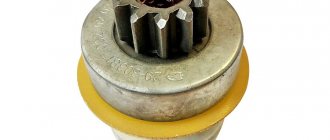
VAZ 2114/2115 cars are equipped with 1.5 cm 3 and 1.6 cm 3 gasoline engines with a distributed injection system. A submersible electric fuel pump is used to supply fuel. It is part of the fuel module installed at the top of the gas tank (under the rear seat). In addition to the pump, the module includes a fuel accumulator (cup), a coarse filter and a fuel level sensor with a float.
To supply fuel in VAZ 2114/2115 cars, a submersible electric fuel pump is used
The VAZ 2114/2115 fuel pump is a conventional DC electric motor in a sealed housing with a one-way valve at the outlet. An impeller of a special shape is located on the electric motor shaft. Its rotation ensures the fuel supply.
Selecting and replacing the fuel pump
Russian car owners prefer BOSH fuel pumps. You should only buy a new pump in specialized stores. The original product must be packaged in thick plastic film filled with special preservative oil. At the same time, a branded BOSH pump cannot cost less than 2 thousand rubles.
Video: how to distinguish an original from a fake
To replace the electric fuel pump on a VAZ 2114/2115 you will need:
- screwdriver with Phillips bit;
- thin slotted screwdriver;
- key or head 7;
- key to 10;
- key to 17.
Video: dismantling the fuel pump
The sequence of actions is as follows:
- Using a 10mm wrench, remove the negative terminal from the battery.
- Open the gas tank cap to reduce the pressure in it.
- Remove the rear seat cushion and peel back the carpet and sound insulation.
The fuel module hatch is located under the rear seat
Disconnecting the electrical connector from the fuel module
Using a 17 wrench, unscrew the nuts on the fuel pipes
Using a socket 7, unscrew the eight nuts securing the module cover
Removing the fuel module from the gas tank
Using a screwdriver, remove the retaining rings from the guides
Symptoms of a problem
A malfunction of the fuel pump of VAZ 2114/2115 cars can be diagnosed by the following symptoms:
- when the ignition is turned on, there is no sound of the pump running;
- the engine does not start or starts with difficulty;
- the power unit is unstable at idle, the speed “floats”;
- “dips” appeared during acceleration;
- the motor has lost power.
The same signs also appear when other elements of the fuel system malfunction.
Before you begin diagnosing or replacing the fuel pump, you should make sure that:
- the fine fuel filter is not clogged (it is changed every 7 thousand kilometers);
- the injectors and fuel pressure regulator are operating normally;
- The sensors for mass air flow, throttle position, and oxygen quantity are working properly.
If the detected malfunction is accompanied by the lighting of the “CHECK” lamp on the dashboard, you should set the error code and decipher it.
Pressure system
As you know, a pump is needed to create pressure in the fuel system. To make a correct diagnosis or eliminate the pump altogether, you will have to take pressure measurements. So, the normal pressure at idle is 2.6 atmospheres, with the ignition on - from 3, without a regulator tube - 3.3, with the drain pinched - 7. When you press the gas pedal, the normal pressure will be from 3 to 2.5 atm .
If, when you turn on the ignition, the pressure gauge needle is near zero, it means the pressure regulator is broken. If the gas pressure arrow is near zero, the fuel pump is faulty. When it smoothly creeps up, it’s worth looking at the condition of the VAZ-2114 fuel pump filter.
Diagnostics
A malfunction of the VAZ 2114/2115 fuel pump can be caused by:
- malfunctions in the device’s power supply circuit;
- failure of starting and protection elements (relay and fuse);
- wear of electric motor parts.
Checking the electrical circuit
At the beginning of the diagnosis, you should check the electrical circuit of the fuel pump. To do this you will need:
- car tester (multimeter);
- crosshead screwdriver;
- two pieces of wire about 2 m long.
Checking the electrical circuit is carried out in the following order:
- Turn on the ignition without starting the engine. When the key is in the first position, a click should be heard, characteristic of turning on the relay, followed by a slight whirring of the pump electric motor. If there is no click, the relay is faulty or is not receiving power. If there is a click, but no buzzing, the wiring coming from the relay or the pump motor itself is faulty.
- Under the glove compartment, find an additional mounting block consisting of three relays and three fuses. The pump relay is located in the middle, and the fuse is located to the left of it. Remove the fuse from its socket, test it with a multimeter, and if the result is negative, replace it. When replacing the fuse, please note that it is rated for a maximum of 15 A.
The relay and fuse for the fuel pump on the VAZ 2114/2115 are located in the mounting block under the glove compartment.
Set your multimeter to voltmeter mode. Connect one probe of the device to the relay terminal to which the pink wire fits, and the second to the car body. Turn on the ignition. The device should show the on-board network voltage in the range of 11.7–12.4 V. If there is no voltage, the problem may be a broken wiring or a malfunction of the ignition contact group. In this case, it is better to contact an auto electrician. If power is supplied, check that the relay is working. With the ignition on, use a screwdriver or a piece of wire to close the contacts to which the pink and gray wires go. This closes the circuit bypassing the relay. If the fuel pump works, replace the relay.
The ground wires of the fuel pump are attached to the body with a self-tapping screw
Pressure check
If the pump is working properly, but the engine begins to operate intermittently, you should check the fuel pressure in the system. For this you will need:
- pressure gauge (can be a tire gauge with a measurement limit of 5–7 kPa);
- petrol-resistant hose with a diameter of 10–12 mm and a length of 50–80 cm;
- two clamps for a hose of the appropriate diameter;
- Phillips screwdriver;
- nipple cap;
- dry rag.
In addition, the presence of an assistant is desirable.
The verification procedure is as follows:
- In the engine compartment on the engine fuel rail, locate the pressure measuring fitting (on the right side).
- Remove the plastic cap (plug) from the fitting.
Find the pressure fitting and remove the cap from it
When unscrewing the spool valve, fuel may spray out of the fitting.
Connect the pressure gauge to the fitting using a hose and clamps
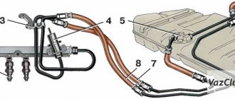
Causes: fuse, relay, connector
The pump power circuit includes many elements: closed relay contacts 5, fuse 3 (15 A), “+” wire, “pump-to-ground” wire. The most “difficult” defect is a short circuit of the “+” wire to ground. By the way, the cord itself is laid on metal, so such a defect cannot be ruled out.
Mounting block for dashboard
Both the relay and the fuse are located in a block located under the dashboard on the right. A fuse can blow in two cases:
- The “+” cord makes contact with ground;
- The motor resistance decreases due to overheating.
The first defect may be “floating”, and then it will be difficult to identify. But before calling an electrician, try checking everything else:
- Relay 5 should click twice: when the ignition is turned on and after 1.5 s. If this does not happen, replace the relay;
- Check fuse 3. If it is blown, you need to look for the cause.
Consider the situation: the relay is working, but the fuse is blown. Then we do this: disconnect the pump connector, install a new fuse and measure the voltage at the terminals. Details are below.
Connectors under the hatch, disconnecting them
You need to remove the hatch under the rear seat: two screws are unscrewed with a Phillips screwdriver. Next you need to disconnect the connector on the module, and then move on to the block under the dashboard.
First, turn off the fuel pump!
Replace the fuse. Let's move on to the fuel pump: connect the probe (zero cord) to any of the mounting studs. Voltage should appear on the “gray” wire when the ignition is turned on. And also check the potential difference between the “gray” and “black” wires - it should be equal to 12 volts, and also at the moment the ignition is turned on. Wiring:
- The two outer cords are the FLS sensor;
- “Black” – minus power supply;
- "Grey" is a plus.
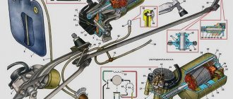
Pinout of fuel pump VAZ 2107
1 – radiator fan drive motor; 2 – mounting block block; 3 — idle speed sensor; 4 – engine ECU; 5 – potentiometer; 6 – set of spark plugs; 7 – ignition control unit; 8 – electronic crankshaft position sensor; 9 – electric fuel pump; 10 – indicator of the number of revolutions; 11 – lamp for monitoring the health of electronic systems and the brake system; 12 – ignition system control relay; 13 – speedometer sensor; 14 – special factory connector for reading errors using the BC; 15 – injector harness; 16 – adsorber solenoid valve; 17, 18, 19,20 – fuse box for repairing the mounting block that protects the injection system circuits; 21 – electronic fuel pump control relay; 22 – electronic relay for controlling the exhaust manifold heating system; 23 – exhaust manifold heating system; 24 – fuse protecting the heater circuit; 25 – electronic air sensor; 26 – coolant temperature control sensor; 27 – electronic air damper sensor; 28 – air temperature sensor; 29 – pressure control sensor and low oil pressure lamp.
You can check the fuel pump on a VAZ 2107 simply by checking the voltage at its connection block with a tester. The presence of voltage will indicate a malfunction of the electric motor. Instead of a tester (multimeter), you can use a test lamp to diagnose a malfunction.
In the absence of one, this can be done by disconnecting the connection block for the fuel pump and fuel level control and applying voltage with wires from the battery to the place where the gray wire is connected +12 and to the place where the black wire is connected - minus. A humming pump will indicate a faulty fuse, power circuit or ECU.
Electrical wiring contacts
There are three wires coming to the device. This is a positive cord, respectively, a negative cord and a fuel level sensor wire. One of the reasons why the pump refuses to work is a power failure. After applying pressure, it is worth checking the contacts.
This can be done using a light bulb. It is secured to the wires and attached to the external connector of the pump. After turning on the ignition, the light should blink. If it still doesn't work, you should check the internal contacts.
If, when testing the external contacts, the lamp did not light up, then in turn connect the negative and positive contacts, which are disconnected from the pump, to ground on the device, and then to the VAZ-2114 fuel pump relay. When the negative contact is connected to ground and the light blinks, the contact is faulty. If not, the positive contact does not work. If the contact is on the relay and the lamp lights up, then it is worth checking the wiring from the pump to the relay.
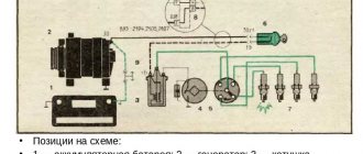
Pinout BN VAZ 2108, 2109, 21099
The fuel pump activation relay (2) is shown by an arrow.
1 — nozzles; 2 — spark plugs; 3 — ignition module; 4 — diagnostic block; 5 - controller; 6 — block connected to the instrument panel harness; 7 - main relay; 8 - main relay fuse; 9 — electric fan relay; 10 — controller power supply fuse; 11- electric fuel pump relay; 12 — fuel pump power circuit fuse; 13 — mass air flow sensor; 14 — throttle position sensor; 15 — coolant temperature sensor; 16 — idle speed regulator; 17 — knock sensor; 18 — crankshaft position sensor; 19- oxygen sensor; 20- APS control unit; 21 — APS status indicator; 22 — speed sensor; 23 — electric fuel pump with fuel level sensor; 24 — solenoid valve for purge of the adsorber; 25 — block connected to the ignition system harness; 26 — instrument cluster; 27 — ignition relay; 28 — ignition switch; 29 — mounting block; 30 — electric fan of the cooling system;
A - to terminal “B+” of the generator; B - block connected to block K of the ignition system harness; C - block connected to block L of the ignition system harness; D - wire connected to the interior lamp switch; E - wire connected to the white and black wires disconnected from the interior lamp switch; F - to the “+” terminal of the battery; G1, G2 - grounding points; K - block connected to block B of the front harness; L — block connected to block C of the front harness.
On “nines” with a mechanical fuel pump, the most common malfunction is wear of the fuel pump diaphragm, as a result of which gasoline will leak through the drainage hole in the housing when it operates. The second reason for the failure of such a fuel pump is wear of the pusher, which transmits force from the camshaft cam to the fuel pump drive lever.
Operating principle of an electric fuel pump
The functional work of the fuel pump is to supply fuel to the injectors. For normal operation of the injectors and creation of the required pressure, the supply of gasoline must begin before the engine starts.
The operating principle of an electric fuel pump includes the following functions: from the gas tank, the pump supplies fuel under pressure through the main fuel filter to the injector ramp. Excess fuel supplied is returned back to the gas tank through a separate drain line.
The electric fuel pump is turned on by a special controller using a relay. When the ignition key is turned to the “starter” or “ignition” position, the controller instantly energizes the fuel pump switch relay, and as a result of the created pressure, fuel is supplied to the injectors.
VAZ 2110 fuel pump pinout
If the fuel pump works directly when connected to the battery, then you will have to ring the wires going from it to the fuel pump relay, and if it does not work, then either replace it with a new one, or you will have to disassemble it and look for a fault inside the fuel pump.
Messages 3
1 Topic by Resmus 2011-04-08 05:44:33
- Resmus
- User
- Offline
- Registered: 2011-04-08
- Messages: 3
- Reputation: [ 0 | 0 ]
Topic: Pinout of fuel pump chips
Please tell me the pinout and description of the wires according to the colors of the chip on the fuel pump.
2 Reply from Sir YareG 2011-04-08 06:00:13
- Sir YareG
- User
- Offline
- Registered: 2008-11-08
- Messages: 3,047
- Reputation: [ 0 | 0 ]
Re: Pinout of fuel pump chips
There are all the options here! Choose yours!
3 Reply from Resmus 2011-04-08 09:49:18
- Resmus
- User
- Offline
- Registered: 2011-04-08
- Messages: 3
- Reputation: [ 0 | 0 ]
Re: Pinout of fuel pump chips
There are all the options here! Choose yours!
Pinout BN VAZ 2113, 2114, 2115
— block headlights; — gearmotors for headlight cleaners*; - fog lights*; — ambient temperature sensor; - sound signals; — engine compartment lamp switch; — electric motor of the engine cooling system fan; — generator; — low oil level indicator sensor; — washer fluid level sensor; — front brake pad wear sensor; — wire tips connected to the common windshield washer pump**; — windshield washer pump; — headlight washer pump*; — wire ends for connecting to the rear window washer pump on VAZ-2113 and VAZ-2114 cars; — low oil pressure indicator sensor; — engine compartment lighting lamp; — wire lug for connecting to the wiring harness of the engine control system; — gear motor for windshield wiper; — starter; — a block connected to the wiring harness of the ignition system on carburetor cars; — coolant temperature indicator sensor; — reversing light switch; — low brake fluid level indicator sensor; - accumulator battery; — low coolant level indicator sensor; — relay for turning on fog lights; - mounting block; — brake light switch; — plug socket for a portable lamp; — hydrocorrector scale illumination lamp; — switch for the parking brake indicator lamp; — block for connecting a backlight lamp; — switch for instrument lighting lamps; - Understeering's shifter; - hazard warning switch; — front seat heating element relay; — ignition switch; — rear fog light circuit fuse; - fuse for the front seat heating elements; — door lock circuit fuse; — front ashtray illumination lamp; — ignition relay; - cigarette lighter; — glove box lighting lamp; — switch for the glove compartment lighting lamp; — heater fan electric motor; — additional resistor for the heater electric motor; — heater fan switch; - heater switch illumination lamp; — lamp for illuminating the heater levers; — gear motors for electric windows of the front doors; — power window switch for the right front door (located in the right door); — gear motors for locking front door locks; — wires for connecting to the right front speaker; — gearmotors for locking rear doors; — wires for connecting to the right rear speaker; — door lock control unit; — wires for connection to radio equipment; — headlight cleaner switch*; — rear window heating element switch; — relay for turning on the rear fog lights; — block for connection to the heating element of the right front seat; — rear fog light switch; — switch for the heating element of the right front seat; — fog light switch*; — switch for external lighting lamps; — left front seat heating element switch; — block for connection to the heating element of the left front seat; — wires for connecting to the left front speaker; — power window switch for the left front door (located in the left door); — power window switch for the right front door (located in the left door); — wires for connecting to the left rear speaker; — side direction indicators; — courtesy light switches on the front door pillars; — courtesy light switches on the rear door pillars; - lampshade; — ceiling lamp for individual interior lighting; — block for connecting to the wiring harness of the electric fuel pump; — trunk light switch; — instrument cluster; — trunk lighting lamp; — display unit of the on-board control system; - trip computer*; — block for connecting the wiring harness of the engine control system; — rear exterior lights; — rear interior lights; — pads for connecting to the rear window heating element; — license plate lights; — additional brake signal located on the spoiler.
Replacing an electric fuel pump on a VAZ
- Reduce pressure in the fuel supply system.
- Using the fuel supply hose tip clamp, disconnect 2 hoses in turn.
- Unscrew the 8 nuts around the circumference of the clamping ring and remove it.
- A wire with negative polarity is attached to one of the nuts; it must be removed carefully.
- We take the electric pump block out of the fuel tank, tilting it slightly, to keep the fuel level indicator sensor lever intact, otherwise it will produce incorrect parameters.
- Remove the sealing rubber ring of the fuel block. If its properties are lost, the product must be replaced.
- Install the pump in reverse order.
When installing fuel hoses, focus on the direction of fuel supply indicated by the arrows, and the installation arrow on the electric pump cover should point towards the rear of the car!
Popular breakdowns
Problems with the fuel pump can occur for several reasons. Therefore, your first priority is to determine the source of the problem. These may be:
- Fuel pump fuse;
- Fuel pump relay;
- Pump weight;
- Motor;
- Contacts;
- The pump itself.
If one of these elements fails, it can stop the normal functionality of the entire module.
Let us consider the situations with each of the specified elements of the fuel module in more detail.
Where is the fuel pump relay located?
Where is the fuel pump relay located? The installation location of the relay varies depending on the make of the car. Most often, it is located under the hood, in the fuse and relay box.
The fuel pump relay is designed in the circuit to prevent accidental application of high voltage to the fuel pump winding. The relay is standard and consists of a plastic body and coils with contacts. It is located in the car interior near the console. To access it, you need to remove the protection cover.
In appearance, it is a small box that resembles a “plug” with an American type of output. Each terminal has a marking that indicates the following: 31 – mass; 30– +12V constant (regardless of ignition); 15– +12 with the ignition on; 50– +12 when the starter is running; TD – signal from the ignition system; TF – engine temperature signal from the injection control unit KE. Outputs: 87 – supplies power to the fuel pump; 87H – oxygen sensor heating; 87V – turns on the starting injector.
But sometimes the fuel pump does not turn on when the key is turned in the ignition. With what it can be connected? First of all, the fuse, although if it had blown, it would not work at all. Maybe the contact is bad?
If the electric fuel pump does not show any signs of life when the ignition is turned on, this does not mean that it has burned out. The cause of the malfunction may also be a relay. The easiest way to test your hearing is that when you turn on the ignition, the relay should click. If you don’t hear a click, there is a high probability that the “relay” is faulty.
It’s easy to check the functionality of the pump itself, so we do this:
- remove the protective casing, under which there is a block with relays and fuses;
- we unscrew the fastenings of the block, remove it, it remains attached to the wires;
- we pull the RB out of the block, place a jumper between two opposite contacts, thus directly supplying power to the BN;
- if with such a connection the electric motor of the pump begins to make noise, it means that the BN itself is working, most likely the fault is hidden in the relay;
- if there is no voltage on any of the contacts on the RB block, you should look for a break in the wiring; there may also be poor contact at the place where the wire is attached to the terminal.
Where to look for the connector
It is important to know that on different cars the required socket is located in different parts of the car. Moreover, on some AvtoVAZ models it may be in a completely different place compared to another car. Let's look at several VAZ cars as an example:
- on the VAZ-2112, as well as on the 2110, as well as 2111, the socket is located to the right of the driver’s seat, immediately under the column;
- on models 2108, 2109 and 21099, the socket you need is located under the glove compartment, on a special shelf;
- on cars with a europanel it can be found in the center of the console, near the cigarette lighter. A special decorative cover is used to disguise it;
- on Lada Kalina cars, the connector can be found near the gear shift lever. As is the case with cars with a Europanel, it is hidden under a special cover;
- on a Priora you need to look for it right behind the glove compartment, on the wall.