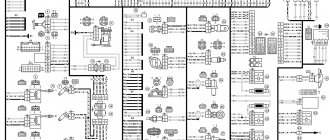
The elements are connected to instruments or controls: 1 – button for the heated rear glass switch; 2/6 – fog light switches, for rear/front module; 3 – plastic block for activating head optics and turn signals; 4 – fuse block; 5 – wiper mode switch; 7 – on-board system indication; 8 – supply voltage to the additional harness; 9 – dashboard; 10 – “male” for powering the on-board computer; 11 – terminal to the ignition device; 12 – for door wiring; 13/14 – fuses; 16 – ignition break; 17 – stove motor; 18 – secondary resistance of the stove; 19 – current supply to the ignition unloading relay; 20 – protective relay for rear fog lights; 21 – starter fuse relay; 22 – remote socket for a portable lamp; 23 – power supply for the cigarette lighter; 24 – for illumination of the glove box; 25-27 – illuminators; 28 – stove switch; 29 – tidy lighting with rheostat; 30 – stop switch; 31/32 – horn/hazard warning switch, respectively; 33 – backlight of the stove panel; 34 – fuse; 35 – protective relay for seat heating elements; Ш1/4 – mounting block jumpers; X1/2 – dashboard controls; A – protective ground output (usually black).
Electrical equipment of the front of the car
The following is a breakdown of the front cable bundle, excluding fog lights:
- 1 – output terminals of the starter contact group;
- 2 – battery, connection of power cables;
- 3 – standard “father” of the generator;
- 4 – blocks for connecting the power conductors of the battery and generator to the front assembly of electrical equipment;
- 5 – part of the fuse mounting block;
- 6 – standard horn;
- 7 – sensor that measures the temperature of antifreeze in the power plant;
- 8 – standard sensor for measuring the washer fluid residue in the tank; when activated, the corresponding indicator on the device lights up;
- 9/10 – left and right headlights, respectively;
- 11 – external thermometer;
- 12 – standard reverse gear lamp switch;
- 13 – drive of the electric fan of the generator;
- 14 – connector to the ignition system module;
- 15 – in the VAZ 2114 scheme the injector is not used, it is used only for the carburetor;
- 16 – electronic brake fluid level sensor; in case of a critical drop, an exclamation mark lights up on the instrument panel;
- 17 – built-in oil level sensor in the crankcase compartment of the power plant; when activated, the red light on the instrument panel lights up;
- 18 – similar for the engine cooling system;
- Ш5-8 – mounting block connectors;
- A1/2, B1/2 – grounding terminals.
Conventional numbering of plugs in blocks
| Designation | Description |
| A | Unit of headlights and their cleaners for a VAZ 2114 car |
| B | Lighting devices |
| IN | VAZ 2114 mounting block, instrument cluster, VAZ 2114 ignition cut-off device, windshield wiper and other components of the vehicle's electronic equipment (the numbering is similar for blocks with a different number of plugs) |
| G | Rear fog light relay |
| D | Alarm disconnect device |
| E | Motor gearboxes for electronic window lifters and door lock locking elements |
| AND | Interior lighting lamp |
The other ends of the white cables in the instrument panel wiring harness are brought together to one point. The switch for the instrument lights is connected to it (except for the white cable connected to plug “4” of block “X2” of the mounting block (28) and to the display unit of the on-board control system (83). The second ends of the black cables are also brought together at points that connected to the mass.
The second ends of the yellow cables with a blue stripe are brought together to a point that is connected to plug “4” of the “X1” block of the mounting block of the VAZ 2114 car. The second ends of the white cables with red stripes are brought together at the point that is connected to plug “10” “X4” block of the mounting block of the VAZ 2114 car. The second ends of the orange cables are brought together to a point that is connected to plug “3” of the “X4” block of the mounting block of the VAZ 2114 car.
Wiring diagram VAZ 2114 injector: decoding of rear harness contacts
Here are the conclusions of the equipment located in the rear of the vehicle:
- 1 – output of the mounting unit;
- 2 – windshield heater;
- 3 – electric drive of the rear wiper gearbox;
- 4 – diodes for illuminating the stern license plate;
- 5 – license plate illuminator directly, some users connect diode strips here for better lighting;
- 6/7 – illuminated direction indicators, for the left and right sides, respectively;
- 8 – lamp for individual illumination of useful space;
- 9 – interior lighting lamp, usually located in the ceiling, above the steering seats;
- 10 – handbrake lever position indicator;
- 11/12 – left and right side lighting lamp;
- 13 – power supply to the additional brake light indicator;
- 14-17 – group of interior lighting switches located in the door pillars;
- Ш9 – terminal block of the fuse mounting device;
- A1 – license plate grounding;
- A2/7 – standard grounding points.
Diagram of side lights, brake lights, interior lighting
- Side light bulbs in headlights;
- Engine compartment lamp;
- Mounting block;
- Engine compartment lamp switch;
- Ignition switch;
- External lighting switch (fragment);
- External lighting indicator lamp in the instrument cluster;
- Lamps for side lights and brake lights in the outer rear lights;
- License plate lights;
- Instrument lighting regulator;
- Brake light switch;
- On-board control system unit;
- K4 - Relay for monitoring the health of lamps (contact jumpers are shown inside the relay, which must be installed in the absence of a relay);
- A - to power supplies;
- B - to the backlight lamps of switches and devices;
- C - to an additional braking signal.
Electrical connection diagram for VAZ 2114, additional segment
Here are grouped auxiliary equipment that is not related to the power plant or on-board computer of the car:
- 1 – contact group of wiring from the doors to the instrument panel block;
- 2 – a similar terminal intended for connecting heated seat devices for the driver and front passenger;
- 3/4 – central locking drive, sections of the front left and right doors, respectively;
- 5/6 – contact blocks of the front right and left speakers, respectively;
- 7 – electronic central locking control unit;
- 8/9 – connecting door parts of electrical equipment to the auxiliary left beam;
- 10 – terminal for connecting the standard speaker system;
- 11 – “mother” of doors to the right wiring harness for connecting electrical equipment;
- A1 – connection of grounding electrical wiring.
Physically, the output is connected to the dashboard, with a contact group located near the hood opening handle. The corresponding fuse is also located here.
VAZ 2114 wiring diagram: section of the right front door
The cut is a simplified concept due to the minimal amount of equipment. The most budget version is completely absent.
- 1 – “mother” of the rear harness, suitable for the door wiring;
- 2 – power supply to the electric motor for the front passenger window;
- 3 – terminal block to the standard door speaker;
- 4 – door lock servo motor (part of the central lock);
- 5 – power switch and power window drive mode switch;
- A – grounding bus.
Diagram of low beam, high beam, rear fog lamps
- Headlights;
- Mounting block;
- Headlight switch;
- Ignition switch;
- External lighting switch (fragment);
- Fog lamps in the interior rear lights;
- Fog light switch with turn-on indicator lamp;
- Headlight high beam indicator lamp in the instrument cluster;
- K8 - High beam headlight relay;
- K9 - Relay for low beam headlights;
- A - The order of conditional numbering of plugs in the headlight block;
- B - to power supplies.
Wiring diagram VAZ 2114: driver's door
A larger section of standard on-board wiring:
- 1 – contact group for connecting to the wiring of the additional bundle;
- 2 – similar output to the aft left beam;
- 3 – electric window motor drive;
- 4 – standard output of the block to the front speaker of the standard acoustic system;
- 5 – door lock drive;
- 6/7 – power window control buttons, for left and right, respectively;
- A1 – standard protective grounding terminal.
Wiring diagram VAZ 2114 injector - a separate section of seat heating equipment
A specially dedicated section of on-board wiring responsible for powering, activating and adjusting seat heater devices. Here is a detailed description of all structural elements:
- 1 – driver’s seat heater;
- 2 – output to the terminal block of the dashboard;
- 3 – separate connector for the driver’s door, wire supply to the control button;
- 4 – heating element of the front passenger seat;
- 5/6 – adjustment key for the element specified in paragraphs No. 1 and 4;
- A1 – grounding wire, fastened with a bolt to the car body.
Instructions for installing a new panel
If you want to replace a low tidy with a more advanced, high one, then in any case you will have to change the entire center console.
Removal and installation instructions look like this:
- First, you need to turn off the power to the on-board network; to do this, disconnect the battery, remove the steering wheel, as well as the steering column switches and the ignition switch. You will also need to disconnect the ignition relay.
- Next, unscrew the two bolts that secure the control panel visor and remove it.
- Now you need to compress the spring and remove the shield itself from the center console. Disconnect all wires and connectors connected to the dash, including the speedometer cable, the econometer hose, and the odometer cable. After this, the tidy can be moved to the side.
- Then remove the regulator from the hydrocorrector of the optics light, the tidy light switch knob, as well as the interior heater and fan regulators. To do this, pull the controls towards you.
- After this, unscrew the two bolts securing the center panel trim on the sides; the trim itself can be moved towards you. Then you need to disconnect the connectors.
- Now the key in the lock should be turned to position “0”, this will disable the anti-theft system. A connector with wires is connected to the lock itself; it must be disconnected. Next, unscrew the two nuts and two bolts, after which you can remove the steering column pipe with the switch.
- Remove the choke handle located under the instrument panel. Pull it towards you so that you can feel the pull. You need to unscrew the two bolts that secure the damper guide rod, after which the choke can be removed.
- Now you can unscrew four more screws that secure the heater control panel in the car. Unscrew the bolts located on the side of the shield on both sides. Also unscrew the lower console mounting bolts with nuts that secure the control panel lighting switch and the optics hydraulic corrector. To do this you will need a 22mm socket wrench, it must be high.
- After completing these steps, you need to unscrew the bolt that secures the center console in the glove compartment. Then all you have to do is unscrew one bolt at a time on each side securing the center console. The console itself can then be dismantled.
- As for installing a new high panel with tidy, this process does not present any particular difficulties. All dimensions at the mounting points on the body are the same, but this procedure also has its own characteristics. To install your new console, you will need the appropriate wiring harness. If you use an existing harness, then you will need to rearrange the terminals in it, taking into account the connection diagram. In addition, it will be necessary to change the cables leading to the heater to longer ones, the same applies to the speedometer cable. If you are installing a new console, you will also need other roof pillar side trims, these must be installed before you install the console. Since the new dashboard will not use a flow meter, the tube from it will need to be plugged. In addition, the signal to the tachometer will need to be supplied from wire K on the coil, which is connected to the speed sensor cable bracket.
- Immediately before installation, you should reassemble the new console, and wrap the connection points of the blowers with electrical tape and, preferably, glue them with foam rubber or anti-creaking agent. It is also necessary to change the foam rubber of the heater, since the old one will no longer be able to perform its functions. Also make sure that the choke can close completely and remember that the cable from the new speedometer should be installed before you install the console. The assembly procedure begins with laying a new wiring harness and connecting all connectors. Before you finally assemble everything, turn on the dashboard and check how all the indicators and gauges work. After this, the console can be put back in place.
Source
Pinout of on-board computer VAZ 2114
In standard drawings of electrical equipment, the BC block section is missing due to its uselessness. Initially, it is assumed that the motorist will not independently repair or maintain the complex control unit. But some users still take risks and install the system themselves. In older versions of cars, such a module is missing or insufficient for comfortable operation of the car in its modern form.
To connect wires to the module, you will need to buy a standard 9-pin header and connect the following wires to it:
- 1 – green wire comes from the fuel consumption sensor;
- 2 – the ignition cylinder is powered through an orange cable;
- 3 – power core from the battery, usually a red wire with a white stripe is supplied;
- 4 – grounding or ground, standard color – black;
- 5 – 6k line, usually a gray wire;
- 6 – Mute – green shell with a red line;
- 7 – the backlight in the standard pinout is output from the marker optics key;
- 8 – a sensor that displays the remaining fuel in the car’s gas tank can be connected directly.
How to prevent electrical equipment breakdowns?
In order for the VAZ 2114 pinout to be required as rarely as possible, the user is required to follow a number of simple rules and recommendations.
- Periodically treat all metal parts with special oil. In this case, it is first necessary to clean the copper patches from oxides and traces of corrosion. Such lesions provoke a deterioration in the transmission of signals, which can be perceived by the car as a breakdown.
- Every 20-30 thousand kilometers, check all equipment and plastic plugs for looseness or reduced fastening rigidity. With constant vibrations typical of vehicles, plastic clamps can fail and cause breakdown.
- Monitor the correct battery charge and the serviceability of the generator. Some machine devices do not work correctly when there is a strong voltage drop.
- Every 40,000 km, check the condition of the wires themselves. With constant use, the braids of the power cores may crack or dry out, which increases the likelihood of a short circuit in the on-board lines. This may also cause a fire.
How to connect and install
It is recommended to install and configure any musical device on the VAZ-2114 in accordance with generally accepted rules. Only in this case will the equipment work efficiently and perform all its functions.
Are you a car driver?! Then you can take this simple test and find out. Go to test »
Connection
To connect a radio to a VAZ-2114, just familiarize yourself with the procedure provided for any similar model (2115, 2109). The only difference will be in the location of one or another wire.
Connect the radio using this method:
- Connect the musical equipment connector to the positive and negative poles of the power source (battery). In this case, the cigarette lighter plug can be used for switching.
- Remove the cables from the speakers and connect them to the corresponding outputs on the device plug.
- As soon as the wiring is connected, all potentially dangerous places are isolated using special tape. You can additionally protect the cable from accidental contact and the negative effects of moisture by using a corrugated tube.
- An antenna is installed on the inside of the windshield or roof of the vehicle.
- The cable running from it to the dashboard is laid under various parts of the car's interior trim.
- The wire is connected to the radio directly or through an adapter.