The VAZ 2114 (Samara-2) car is built on the VAZ 21093 platform and is an improved version of it. The first prototype of the hatchback was assembled back in 2000. A year later, the Volzhsky Automobile Plant produced the first pilot batch of 50 VAZ-2114 cars, and in the same 2001 the hatchback was first introduced to the market. The interior features a new instrument panel, a new steering wheel, an adjustable steering column, power windows and a new heater. Years of production 2114: 2001—2013
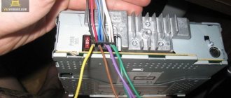
The fourteenth model was previously equipped with a 1.5 liter eight-valve engine, borrowed from the VAZ 2111 model with an injector. A little later it was replaced by the VAZ 11183-1000 version, which complies with the Euro-3 standard. The VAZ 2114 injector received a more powerful engine, and this is one of the reasons that the wiring of the 2114 has also changed.
A wiring harness has been added for connecting to the electronic switch. A harness has also appeared for connecting to the ignition module terminal.
Replacing high-voltage wires will require additional attention, because the connection procedure depends on the year of manufacture of the car. Until 2004, 4-pin ignition modules were installed, and after that - 3-pin. Connecting the adsorber valve to the injection system controller also provided another additional element. An adsorber is an electromechanical device used for ventilation and removal of condensate in a gas tank. Complications also affected the interior part. The dashboard received improvements in the form of the appearance of a BC (on-board computer), a new instrument panel and a change in the position of the glove compartment.
Car modifications 2114
VAZ-21140 . Modification with an 8-valve injection engine VAZ-2111, 1.5 liters and 77 horsepower. Serial production from 2003 to 2007
VAZ-21144 . Modification with an 8-valve VAZ-21114 engine, 1.6 liters and 81.6 horsepower. Years of serial production: 2007-2013.
VAZ-211440 . Another modification released in 2007, it was equipped with a VAZ-11183 engine with a volume of 1.6 liters and a power of 82 horsepower. The car was discontinued in 2013.
VAZ-211440-24 . Released in 2009, a modification with an injection 16-valve VAZ-21124 engine with a volume of 1.6 liters and a power of 89.1 horsepower. Discontinued in 2013.
VAZ-211440-26 . Modification with a 16-valve injection engine VAZ-21126, which complies with the Euro-3 environmental standard, with a volume of 1.6 liters and a power of 98 hp. The car was produced from 2010 to 2013.
Maintenance of the electrical wiring system in Lada Samara
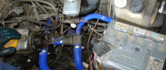
In a car with an injection or carburetor engine, maintenance of electrical wiring consists of protecting and repairing it. The electrical equipment in the car will last a long time, and it will only have to be repaired as a last resort if you carefully ensure that no moisture gets into the wiring system, and that high-voltage wires are not tangled and are located as far as possible from the hot parts of the engine. The VAZ 2115 electrical diagram will help with this.
You need to pay special attention to the condition of the contacts and connectors; if necessary, they should be cleaned of dirt and dust. Burnt out sections of wiring should not be replaced; it is much better to replace the entire wire. The VAZ 2115 wiring diagram will become a visual aid and will help you carry out minor repairs yourself or even completely replace the electrical wiring in the car. The VAZ 2115 diagram is clear and intuitive to the user; its especially important details are highlighted in color or a different font.
Without a diagram of the location of electrical components in a machine with 8 valves, it is impossible to repair or replace the main relay or other unit.
Often the cooling fan does not turn off due to a failed fan relay. It is installed in an additional mounting block “four”. This block is located near the front passenger's feet and is covered with a decorative trim.
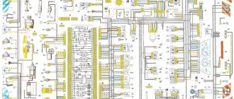
Wiring diagram VAZ-2114 for old models
Electrical diagram of car 2114: 1 – headlight; 2 [Installed on a part of the car] – fog lamp; 3 – ambient temperature sensor; 4 – electric engine radiator fan; 5 – block for connection to the wiring harness of the engine control system; 6 – engine compartment lamp switch; 7 [Installed on a part of the car] – reserve block for connecting an audio signal with one terminal (the negative terminal is connected to the body); 8 – sound signal; 9 – liquid level sensor in the windshield washer reservoir; 10 [Installed on a part of the car] – brake pad wear sensor; 11 – low oil level sensor; 12 – generator; 13 [Installed on a part of the car] – engine compartment lamp; 14 – temperature indicator sensor; 15 – starter; 16 – battery; 17 [Installed on a part of the car] – relay for turning on fog lights; 18 – coolant level sensor in the expansion tank; 19 – sensor of insufficient brake fluid level; 20 – reverse light switch; 21 – windshield wiper gear motor; 22 – emergency oil pressure sensor; 23 – rear window washer electric pump; 24 – electric pump for windshield washer; 25 – instrument panel; 26 – mounting block of fuses and relays; 27 – brake signal switch; 28 – ignition relay; 29 - ignition switch (lock); 30 – glove box lighting lamp; 31 – switch for the glove compartment lighting lamp; 32 – rear window heating switch; 33 – rear fog light switch; 34 [Installed on a part of the car] – fog light switch; 35 – combined switch for side lights and headlights; 36 – alarm switch; 37 – steering column switches; 38 – brightness control for instrument lighting; 39 – illumination lamp for the headlight hydraulic adjustment control handle; 40 – socket for connecting a portable lamp; 41 – side direction indicator; 42 – interior lighting switch (front door open sensor); 43 – interior lamp; 44 – electric fan of the ventilation and heating system; 45 – additional resistor of the electric fan of the ventilation and heating system; 46 – switch for operating modes of the electric fan of the ventilation and heating system; 47 – illumination lamp for the handle of the operating mode switch of the electric fan of the ventilation and heating system; 48 – backlight lamp for the heater control unit; 49 – display unit of the on-board control system; 50 [Installed on part of the car] – trip computer; 51 – interior lighting switch (rear door open sensor); 52 [Installed on a part of the car] – block for connecting a clock; 53 – fuel module; 54 – ashtray illumination lamp; 55 – cigarette lighter; 56 – interior lamp; 57 – switch for the parking brake warning lamp; 58 – rear light; 59 – license plate light; 60 – additional brake light; 61 – heating element for heating the rear window; 62 – rear window wiper gear motor; A – pin numbers in the connecting blocks.
Operating principle
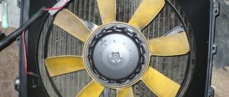
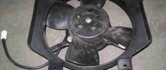
A fan is a device that allows you to increase the efficiency of a cooling radiator. The radiator takes heat from the engine and releases it into the air. This process is accelerated by blowing through the blades of an electric fan.
The coolant flows through a closed, sealed system. Its task is to remove excess heat from overheated engine parts. Hot antifreeze flows into the radiator, is cooled here and returns back. While in the radiator, the coolant passes through a system of thin tubes. The incoming air flow while the car is moving helps to quickly remove excess heat from the engine compartment.
But when the car is stuck in traffic or idling, the air flow stops cooling it. In this case, the cooling system may not cope with its task. An electric radiator fan is designed to create air flow artificially. The temperature for turning on the fan on a VAZ 2114 is 85 degrees Celsius.
Having received a signal that the permissible temperature value has been exceeded, the sensor starts the device’s operating mechanism. An artificial air flow is created that removes heat from the radiator. The mechanism operates until the temperature level drops to an optimal state.
The thermal switch then receives a signal that the normal temperature has been reached and turns off the fan.
The device consists of four plastic blades that are mounted on the EDF shaft. A special controller regulates the automatic operating mode. The thermostat is equipped with a solid filler that is sensitive to temperature changes.
There are main and additional valves. When the temperature reaches 85 degrees Celsius, the main valve opens.
VAZ-2114 diagram (second option)
Electrical diagram of VAZ-2114 cars (without engine control system):
1 – headlights; 2 – fog lights; 3 – air temperature sensor; 4 – electric motor of the engine cooling system fan; 5 – blocks connected to the wiring harness of the ignition system; 6 – engine compartment lamp switch; 7 – block for connection to a single-wire type audio signal; 8 – sound signal; 9 – washer fluid level sensor; 10 – front brake pad wear sensor; 11 – oil level sensor; 12 – generator; 13 – engine compartment lamp; 14 – coolant temperature indicator sensor; 15 – starter; 16 – battery; 17 – relay for turning on fog lights; 18 – coolant level sensor; 19 – brake fluid level sensor; 20 – reverse light switch; 21 – windshield wiper gearmotor; 22 – oil pressure warning lamp sensor; 23 – block for connecting to the rear window washer electric motor; 24 – electric motor for windshield washer; 25 – instrument cluster; 26 – mounting block 2114; 27 – brake light switch; 28 – ignition relay; 29 – ignition switch; 30 – glove box lighting lamp; 31 – glove box lighting switch; 32 – rear window heating element switch; 33 – rear fog light switch; 34 – fog lamp switch; 35 – switch for external lighting lamps; 36 – alarm switch; 37 – steering column switches; 38 – switch for instrument lighting lamps; 39 – illumination lamp for the headlight hydrocorrector scale; 40 – plug socket for a portable lamp; 41 – side direction indicators; 42 – lamp switch on the front door pillars; 43 – canopy for individual interior lighting; 44 – heater fan electric motor; 45 – additional resistor of the heater electric motor; 46 – heater fan switch; 47 – heater switch illumination lamp; 48 – backlight lamp for heater levers; 49 – on-board control system unit; 50 – trip computer; 51 – lamp switch on the rear door pillars; 52 – block for connecting the wiring harness of the engine control system; 53 – electric fuel pump and gasoline quantity sensor; 54 – front ashtray illumination lamp; 55 – cigarette lighter 2114; 56 – trunk lighting lamp; 57 – trunk light switch; 58 – interior lamp; 59 – parking brake warning lamp switch; 60 – rear external lights; 61 – rear internal lights; 62 – block for connection to the rear window heating element; 63 – license plate lights; 64 – additional brake signal located in the spoiler.
Conventional numbering of plugs in blocks:
- A – headlight blocks;
- B – electric fuel pump block;
- C – blocks of the mounting block, ignition switch, windshield wiper gearmotor;
- D – blocks for the interior lighting.
Useful: Diagram of VAZ-2123 Niva Chevrolet
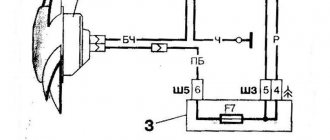
Diagram of low beam, high beam, rear fog lamps
- Headlights;
- Mounting block;
- Headlight switch;
- Ignition switch;
- External lighting switch (fragment);
- Fog lamps in the interior rear lights;
- Fog light switch with turn-on indicator lamp;
- Headlight high beam indicator lamp in the instrument cluster;
K8 - High beam headlight relay;K9 - Relay for low beam headlights;
A - The order of conditional numbering of plugs in the headlight block;
B - to power supplies
Wiring diagram VAZ-2114 new models
The updated engine has a new injection scheme, so it was necessary to use some new devices, as well as replace the ignition coil with a more efficient one and adapted to Euro 3 conditions. In order to comply with them, the engine had to minimize the amount of CO at start-up. And for this it was necessary to lean the mixture. Since a lean mixture ignites worse, it needed a more powerful spark to spark. This explains the use of a coil of increased power.
- block headlights;
- gearmotors for headlight cleaners*;
- fog lights*;
- ambient temperature sensor;
- sound signals;
- engine compartment light switch;
- engine cooling fan electric motor;
- generator VAZ-2114;
- low oil level indicator sensor;
- washer fluid level sensor;
- front brake pad wear sensor;
- wire ends connected to the common windshield washer pump**;
- windshield washer pump;
- headlight washer pump*;
- wire ends for connecting to the rear window washer pump on VAZ-2113 and VAZ-2114 cars;
- low oil pressure indicator sensor;
- engine compartment lamp;
- wire lug for connecting to the engine management system wiring harness;
- windshield wiper gear motor;
- starter VAZ-2114;
- block connected to the wiring harness of the ignition system on carburetor cars;
- coolant temperature indicator sensor;
- reverse light switch;
- low brake fluid level indicator sensor;
- accumulator battery;
- low coolant level indicator sensor;
- relay for turning on fog lights;
- mounting block;
- brake light switch;
- plug socket for a portable lamp;
- hydrocorrector scale illumination lamp;
- parking brake indicator lamp switch;
- block for connecting a backlight lamp;
- switch for instrument lighting lamps;
- Understeering's shifter;
- hazard switch;
- front seat heating element relay;
- ignition switch;
- rear fog lamp circuit fuse;
- front seat heating elements circuit fuse;
- door lock circuit fuse;
- front ashtray illumination lamp;
- ignition relay;
- cigarette lighter VAZ-2114;
- glove box lighting lamp;
- glove compartment light switch;
- heater fan motor;
- additional heater motor resistor;
- heater fan switch;
- heater switch illumination lamp;
- heater lever illumination lamp;
- gear motors for electric windows of the front doors;
- right front door ESP switch (located in the right door);
- gear motors for locking front door locks;
- wires for connecting to the right front speaker;
- gear motors for locking rear doors;
- wires for connecting to the right rear speaker;
- door lock control unit;
- wires for connecting to radio equipment;
- headlight wiper switch*;
- rear window heating element switch;
- rear fog light relay;
- block for connection to the heating element of the right front seat;
- rear fog light switch;
- right front seat heating element switch;
- fog light switch*;
- switch for external lighting lamps;
- left front seat heating element switch;
- block for connection to the heating element of the left front seat;
- wires for connecting to the left front speaker;
- left front door power window switch (located in the left door);
- right front door power window switch (located in the left door);
- wires for connecting to the left rear speaker;
- side direction indicators;
- dome light switches on the front door pillars;
- dome light switches on the rear door pillars;
- lampshade VAZ 2114;
- individual interior lighting lamp;
- block for connecting to the wiring harness of the electric fuel pump;
- trunk light switch;
- instrument cluster;
- trunk light;
- on-board control system display unit;
- trip computer*;
- block for connecting the wiring harness of the engine management system;
- rear exterior lights;
- rear interior lights;
- pads for connecting to the rear window heating element;
- license plate lights;
- additional brake signal located on the spoiler.
Numbering order of plugs in blocks:
A – headlight units and headlight cleaners; B – cigarette lighter; B – mounting block, instrument cluster, ignition switch, windshield wiper and other electrical components (for blocks with a different number of plugs, the numbering order is similar); G – relay for turning on the rear fog light; D – alarm switch; E – electric window motors and door lock motors; F – interior lamp.
In the instrument panel wiring harness, the second ends of the white wires are brought together into one point, which is connected to the instrument lighting switch (except for the white wire, from plug “4” of block “X2” of mounting block 28 to display block 83 of the on-board control system). The second ends of the black wires are also brought together to points connected to ground. The second ends of the yellow wires with a blue stripe are brought together to a point connected to plug “4” of the “X1” block of the mounting block. The second ends of the white wires with a red stripe are brought together to a point connected to plug “10” of the “X4” block of the mounting block. The second ends of the orange wires are brought together to a point connected to plug “3” of the “X4” block of the mounting block.
Explanations for the 8-pin injector block: white-red and blue - for the check light bulb, blue-red - ignition, gray - speed sensor, brown-red - tachometer, blue-white - driver's door switch (for the immobilizer), green- red - K-line (may not exist), green - fuel consumption. Next to it is a pink wire - to the fuel level sensor.
See the complete diagram in one file below (click to enlarge):
Replacement
- socket wrench 10;
- socket wrench 8;
- screwdriver with a Phillips bit.
- We park the car on a flat surface and immobilize it with the parking brake.
- Open the hood and disconnect the negative terminal.
- Using a 10mm wrench, unscrew the fastenings of the air filter housing.
- Using a screwdriver, loosen the air duct clamp on the air flow sensor and remove the corrugation.
- We unscrew the screws securing the cover of the air filter housing and remove the filter element.
- Using a size 8 wrench, unscrew the air intake mount and remove it.
- Using a 10mm wrench, then an 8mm wrench, unscrew the nuts securing the fan casing around the perimeter (6 pieces in total).
- Disconnect the wire block on the fan connector.
- Carefully remove the fan casing along with the drive.
- Using a 10mm wrench, unscrew the 3 bolts holding the electric motor to the casing.
- We put a new one in its place.
- We install the structure in place, fix it, and connect the connector.
- We carry out further installation in the reverse order.
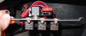
Relays and fuses VAZ 2114
F1 for 10 Amps (A) rear fog lights and rear fog light warning lamp. F2 for 10 A turn signal lamps, turn signal relay, hazard lights, hazard warning lights. F3 7.5 A lamps for interior lighting (both) and trunk, ignition lighting, powertrain control system control lamp, brake lamps, computer, if available. F4 20 A carrier, relay and rear window heating element. F5 20 A horn and its relay, cooling fan. F6 30 A power windows and their relays F7 30 A motor heater, headlight cleaner, windshield washer, cigarette lighter, glove compartment light bulb, rear window heating relay winding. F8 7.5 A right fog lamp. F9 7.5 A left fog lamp. F10 at 7.5 A left side marker, lamp signaling the inclusion of the side light, lamps for illuminating the sign, engine compartment, illumination of switches and instruments, instrument lighting switch. F11 at 7.5 A right side. F12 at 7.5 A right low beam. F13 at 7.5 A left low beam. F14 for 7.5 A left high beam and a light indicating that the high beam headlights are on. F15 at 7.5 A right far. F16 30 A - a light indicating insufficient oil pressure, brake fluid level, engagement of the parking brake, low battery, instrument cluster, relay for monitoring the health of lamps, indication of control systems, reversing lamps, turn indicators and their relays, as well as an alarm if turning mode is turned on, computer, generator excitation winding is turned on at the moment the engine starts.
Diagram of side lights, brake lights, interior lighting
- Side light bulbs in headlights;
- Engine compartment lamp;
- Mounting block;
- Engine compartment lamp switch;
- Ignition switch;
- External lighting switch (fragment);
- External lighting indicator lamp in the instrument cluster;
- Lamps for side lights and brake lights in the outer rear lights;
- License plate lights;
- Instrument lighting regulator;
- Brake light switch;
- On-board control system unit;
K4 - Relay for monitoring the health of lamps (contact jumpers are shown inside the relay, which must be installed in the absence of a relay);A - to power supplies;
B - to the backlight lamps of switches and devices;
C - to additional brake signal
VAZ-2114 wiring harness diagrams
Instrument panel harness
Glove compartment lighting harness
Front harness (without fog lights)
Rear harness VAZ-2114
Wiper Harness
Additional harness
Connects to the instrument panel, the connector is next to the hood handle. Pink - door lock, permanent plus, fuse hangs next to the hood release handle. White and black - on the door for electric windows, plus during ignition, switched on through a relay and fuse in the mounting block. Also in the photo is the wiring for the radio speakers.
Right door harness
Connects to an additional harness.
Left door harness
Connects to an additional harness.
Seat heating harness
The gray wire is connected to the connector where the additional harness is connected (to the gray wire if there is one), plus when igniting, the relay is attached next to the mounting block and the fuse is located next to the hood handle. The white wire is connected to the additional harness, button illumination.
How to make a replacement
If you are convinced that the cause of the malfunction lies in the fan motor, then the easiest way to carry out repairs is to completely replace the device. In this case, there is no point in spending money on a new casing. It will be cheaper to just buy a new electric motor.
Necessary tool
No special tool is needed. The work is carried out simply using 8 and 10 socket wrenches and a Phillips screwdriver.
Step-by-step algorithm of work
You can replace the cooling fan motor without removing the radiator.
- Disconnect the connector and device wiring harness from the casing.
- Unscrew the mounting bolts using a 10mm wrench.
- Unscrew the lower fastening nut.
- Using a 10 mm socket wrench, unscrew the mounting nut from the radiator.
- Using a size 8 socket wrench, unscrew the two pressure plate nuts.
- Remove the plate.
- Remove the electric fan along with the casing.
- Let's start dismantling the electric motor. Using a 10 mm wrench, unscrew the three mounting nuts and remove the engine along with the blades.
- Using a screwdriver, pry up the lock washer.
- And take it off.
- Remove the impeller.
- Put the impeller on the new motor. Make sure that the shaft pin fits into the impeller groove.
- Reassemble in reverse order.
WHAT ARE THE FOLLOWING SIGNS OF MALFUNCTIONS?
When asked what are the signs of a malfunction in the VAZ 2114 ignition module, any driver will say without hesitation that there is no spark at the spark plugs. This is partly true, but there are several other possible reasons for the failure of this device. You can see the following:
- The dynamics disappeared during acceleration, dips in engine performance appeared when the gas pedal was sharply pressed to gain speed;
- A decrease in engine power has become noticeable; drivers say in such cases that the engine does not “pull”;
- The idle speed floats a lot;
- There is no spark on one of the pairs of spark plugs.
When signs of a faulty ignition coil appear, the test should begin with the spark plugs, which do not work, then the sensor indicating the position of the crankshaft is the last module to be checked.
MODULE DEVICE
Design (circuit) of the VAZ 2114 ignition module The device includes two coils, the main task of which is to generate high voltage. A two-channel electronic switch helps them in this. All these parts are contained in a housing made of durable plastic. The housing has a low-voltage connector for connecting the supply voltage and supplying control pulses. There are also leads for connecting high-voltage wires that are connected to the spark plugs.
Electrical diagram of the VAZ 2114 starting system. The figure shows an electrical diagram of the VAZ 2114 starting system. As can be seen from the figure, it consists of:
- Battery;
- Ignition switch;
- Relay that turns on the ignition;
- Hall Sensor;
- Semiconductor signal receiver from the sensor;
- Electronic switch;
- Ignition module.
- High voltage terminals.
The electrical diagram also shows the fuses of the power supply circuits of the electronic units. Let's try to look at the device and operating principle of the ignition coil. As already noted, there are two of them in the block; they are identical in design.
The ignition coil circuits of one and the other are also absolutely identical. The principle of operation of the ignition coil remains the same. Both consist of cores made of electrical steel.
Two windings are wound on them. One of them is low-voltage, and the second produces high-voltage voltage to ignite the working mixture.
The ignition coil connection circuit is made in such a way that one end of the low-voltage winding is connected to the supply voltage, and the other end of these windings is connected to a transistor generator. Each coil has its own transistor. The high-voltage leads are connected directly to the spark plugs; each winding supplies energy to two spark plugs. One of them outputs pulses to cylinders 1 and 4, and the second to cylinders 2 and 3.
The wires on the ignition module are arranged as follows. Contacts A and B receive control pulses from the electronic switch, pin D receives power from the machine’s on-board network. The terminal marked with the letter C is connected to the vehicle ground.
ABOUT THE POSSIBILITIES OF MODULE REPAIR
Most breakdowns of this device lead to its replacement, but sometimes it is possible to repair the ignition coil to return it to service. This is especially true in cases where moving or tapping changes the behavior of the motor. If you have the ability to use a soldering iron and a multimeter, you can try to get it back into operation.
You need to remove the metal back cover, under which the electrical parts of the module are filled. You need to try to carefully get rid of the silicone and its “insides” will be revealed to your eyes. Find broken or “bad” contacts and solder them.
The conductors in the block are aluminum, so special solder is needed to solder them. After this, close the back cover and check its functionality. If the repair result is positive, you need to open it again and fill the inside with silicone.
If the result is negative, then the block must be replaced. True, owners with extensive amateur radio experience continue to “dig” further. You can try replacing the electronic switches. Basically, these two elements become the culprits of failures of the engine starting system.