ZMZ-406. “Charging” hydraulic tensioners
We bring the jaws of the vice together, leaving a gap of 19 mm between them.
Do not squeeze the tensioner body in a vice. When disassembling two hydraulic tensioners at once, do not confuse their plunger pairs, as they are selected with a certain clearance.
Install the tensioner body in a vice, like in a wrench, using a screwdriver with a wide blade.
Remove the spring from the housing.
We wash all parts in gasoline or kerosene, blow with compressed air and lubricate with engine oil.
From a steel sheet 0.8–1.0 mm thick, cut out a strip (10–15 mm wide and 25 mm long). Using round-nose pliers or a mandrel, bend it into a ring with a diameter similar to that of a plunger.
We install the plunger into the body. If necessary, use a thin screwdriver to adjust the locking ring.
Use a screwdriver to press the bottom, pushing the plunger in until it stops.
Use a screwdriver to press the bottom, pushing the plunger in until it stops.
Using a manufactured mandrel, we fix the retaining ring in the hydraulic tensioner housing.
We install a spring in the plunger, and the body itself in a vice.
Overcoming the resistance of the spring, we wrap the valve into the hydraulic tensioner housing.
Use a screwdriver to tighten the valve, holding the body in a vice (as during disassembly).
For a properly “charged” tensioner, the plunger should be held in the body.
ATTENTION To prevent the hydraulic tensioner from being discharged, do not press on the protruding end of the plunger, and after installing the hydraulic tensioner in the channel of the cylinder head, do not press on the tensioner itself.
Source
Incorrect brush replacement
ATTENTION! A completely simple way to reduce fuel consumption has been found! Don't believe me? An auto mechanic with 15 years of experience also didn’t believe it until he tried it. And now he saves 35,000 rubles a year on gasoline! Read more"
As a rule, if the starter has not been repaired for a long time and its brushes have not been replaced, the polarity of the supplied voltage can easily be disrupted. In other words, the positive and negative positions in the starter cables have been reversed. The reason is depressurization of the line and mutual contact of wires.
Another development of events is also likely when the starting device has previously been repaired. The procedure for replacing the brushes this time was carried out incorrectly, the elements were accordingly placed in the wrong sequence. You need to test and determine where the brush with the “plus” polarity is facing. She should look directly opposite the "minus".
Tags: recharging hydraulic tensioner
Comments 24
I had a tensioner of this design unwind in the engine, twice in a row. As a result, the chain weakens, the engine roars like a diesel and the oil pressure warning light is on. Of course, it recharges great, but I installed it without spinning and now everything is fine
everywhere it is written how to do it... even after 3 hours without literature I charged it. Oh you
car-exotic.com/gaz-cars/gaz-31105-engine-13.html
By the way, about the new tensioners. I bought myself something that looked like a rocket (cylindrical in shape without protrusions at the back). So it turns out there is a cork type gasket inside it, located under the spring. the spring breaks this gasket into pieces, they are picked up by the oil flow and clog the grooves of the hydraulic tappets. so now I take it apart and check it before installing it - if it eats, I throw it away.
but it shoots when you insert it into the well, close it with the lid that has two bolts and there is a plug in the center, unscrew it and press the tensioner with a screwdriver! when pressed, the piston will move slightly back and the stopper will take its position on the piston and thus the piston is already free and flies out of the cylinder!
+100500! Only I did it without a mandrel, I just used a flat screwdriver to unscrew this very ring in a circle with the piston inserted. and the main thing is not to press on the end of the piston - otherwise it will discharge and you will have to do everything all over again
yes this is also an option!
but it shoots when you insert it into the well, close it with the lid that has two bolts and there is a plug in the center, unscrew it and press the tensioner with a screwdriver! when pressed, the piston will move slightly back and the stopper will take its position on the piston and thus the piston is already free and flies out of the cylinder!
I also did it with a screwdriver. But the infection doesn’t hold on and shoots out. I also tried to open the ring. It turns out that you need to press down on the tensioner so that the piston presses in? I thought there must be something sticking out of the lid.
there you can even press the bolt in the lid so that it discharges
I also did it with a screwdriver. But the infection doesn’t hold on and shoots out. I also tried to open the ring. It turns out that you need to press down on the tensioner so that the piston presses in? I thought there must be something sticking out of the lid.
and you shouldn’t really unclench the stopper, otherwise it won’t discharge later! decompress only under the influence of its springy properties
I also did it with a screwdriver. But the infection doesn’t hold on and shoots out. I also tried to open the ring. It turns out that you need to press down on the tensioner so that the piston presses in? I thought there must be something sticking out of the lid.
you need to combine the groove on the body with the groove on the piston, where the springy ring is currently located. At the same time, try to make the piston come out a little higher - take a flat screwdriver, place the ring lock on the right or left, press on the lower part of the ring with a screwdriver, it goes to thicken the cylinder and in the groove on the body and while it is held due to friction, you recess the upper part in the same way, as soon as this action is completed, you push the piston up even more until it stops. And if you have a second screwdriver and an assistant, there are no more problems.
Gazelle, gas forum, gas club, gazelle repair, gazelle car
Clutch fork repair cost
At auto repair shops, specialists can provide you with services for replacing the clutch fork. This procedure will cost from 4,000 to 6,000 rubles. It is not necessary to buy parts separately if you are doing the repairs yourself. The entire clutch kit will cost from 3,000 rubles. The cost of the clutch fork itself reaches about 500 rubles.
Video of replacing a car clutch fork:
Adjusting and replacing the clutch on a Gazelle
Replacing the working or master cylinder of the clutch on a Gazelle, as well as other parts, can prevent car failure. It is important to diagnose and repair the vehicle in a timely manner, and replace the clutch kit and other components as needed. In the future, this will help avoid breakdowns on the highway and accidents.
Clutch diagram for Gazelle
To watch online, click on the video ⤵
How to charge hydraulic tensioner 406 405 Read more
HOW TO QUICKLY AND EASILY CHARGE THE HYDRAULIC CHAIN TENSIONER OF ZMZ 409,406 MOTORS. More details
Hydraulic chain tensioners ZMZ 409. Timing belt replacement Euro 4. Read more
How to charge a ZMZ hydraulic tensioner, installing a hydraulic tensioner ★ Keepers of history Read more
Recharging the hydraulic chain tensioner ZMZ-409, Euro-4, with adapter. #2 Read more
how to charge the hydraulic tensioner of the internal combustion engine 406 Read more
ZMZ-406 (405, 409, PRO) useful tips about hydraulic tensioners. Issue-7. More details
ZMZ-406 Hydraulic tensioner recharge Read more
Recharging the hydraulic chain tensioner for ZMZ-406,405,409 engines Read more
Replacement of the upper hydraulic timing chain tensioner of the ZMZ 406 engine. Read more
How to install a chain tensioner on a 406 engine. More details
Chain tensioner for internal combustion engine ZMZ 406 How does it work? More details
Replacement of the lower hydraulic chain tensioner ZMZ 405,409 Read more
How to charge the hydraulic chain tensioner Volga Gazelle ZMZ 405 / 406 / 409 Read more
Replacement of hydraulic timing chain tensioners of the ZMZ 406 engine (Volga) More details
Hydraulic chain tensioner ZMZ 405-406-409 More details
Wind generator based on starter
The idea of making a wind generator appeared when the early autumn nights arrived. I decided to try using wind energy for household needs. Let the wind charge the battery, which will illuminate the garden toilet standing at the edge of the site.
It’s expensive to run a network cable to this object, you’re tired of changing batteries in a Chinese lantern, and then the free, periodically renewable energy is wasted. Since bright lighting is not required at this facility, reading books and the press is not planned, low powers are sufficient to solve this problem.
In practice, this is a generator with a power of several watts and a small-capacity battery. During the day, the battery stores wind energy, and at night releases it as needed. For such wind generators, there is practically no point in performing complex calculations and making special blades.
For use as a low-power wind generator, you can use a ready-made stepper motor. For maximum efficiency, if there is a choice, it is advisable to use a motor with the minimum possible sticking of the shaft (they have such an unpleasant effect) and with the largest possible number of steps per revolution.
It is possible to convert the electric motor into a generator. Various modification options are described on the Internet.
In our case, we chose the option of remaking the used starter 923.3708 from the legendary Oka.
The use of this starter is due to the following factors: • small dimensions and weight of the starter; • the starter is excited by permanent magnets; • ease of modification in the absence of investments for the manufacture of a generator.
The process of converting a starter into a generator
1. Disassemble the starter: Disconnect the power wire and remove the parts of the traction relay. We release and remove the body and shaft of the overrunning clutch and the built-in planetary gearbox.
2. Carefully remove the cover of the brush assembly. At the same time, we monitor the safety of the support ball in the cover bearing. We disassemble and remove the brush assembly. We remove the rotor. Three nodes remain for further use.
3. Using wire cutters and pliers, remove the old starter rotor winding. Mechanically remove the rotor manifold. We clean the shaft and grooves on the rotor plates from any remaining varnish. In the photo, to the right of the new rotor, are the remains of the old winding.
4. We perform mechanical processing of the rotora. Using a lathe or manually, remove the splines for connection to the planetary gearbox and obtain the landing diameter for the second plain bearing.b. Between the set of rotor plates and the treated area, half the diameter, we drill a radial hole with a diameter of 4 mm.
The hardness of the shaft is insignificant and can be processed with high-speed tools.c. On a lathe or manually with a drill, from the side of the treated area, drill an axial hole with a diameter of 4 mm until it coincides with the radial one. We get a hole for the output of the rotor winding. This output circuit eliminates the need for sliding contacts for current collection and increases the reliability of the generator. For greater clarity, the location of the holes and the winding output are shown on the finished rotor.
5. We wind the coil windings into the slots of the rotor until they are filled. The arrangement of six permanent magnets in the stator with alternating poles determined the arrangement of the winding coils.
The width of each coil (number of slots 5) was determined by the distance between adjacent magnets. The turns of each coil, located oppositely in adjacent slots, when the rotor rotates, simultaneously cross the magnetic field of two magnets with different poles. In this case, the induction current in the coil adds up.
To avoid damage to the wire insulation during winding and operation, MGTF stranded wire with a core diameter of 0.30 mm is used. It is possible to use another insulated wire.
6. Due to the absence of a second bearing for the rotor in the used part of the starter (one is located in the cover of the brush assembly, and the second remained in the removed planetary gearbox), we will make a new bronze plain bearing. The outer seat diameter of the bearing is determined by the diameter of the hole in the housing partition (photo below), and the inner diameter of the bearing and the length of the outer steps is determined by the actual diameter and length of the machined section of the rotor shaft (item 4a).
7. We install the manufactured bearing into the housing, and the saved ball at the bottom of the bearing in the cover.
8. We install the machined section of the rotor into the manufactured bearing and assemble the rotor with the housing. Before assembly, lubricate all rubbing parts.
9. Install the brush assembly cover, aligning the second rotor shaft support with the cover bearing and support ball. We align the holes of the body and cover, install the mounting studs from the kit.
10. Assembling the generator. We use the free end of the rotor shaft (with the winding output) to install and secure the generator. We will install a rotor-type wind wheel on the free part of the studs (above the cover).
11. To protect the inside of the generator from dust and moisture, close all free openings with hot-melt adhesive. For testing, I additionally sealed the joints with electrical tape.
12. We make a support for installing the generator on the site.
13. We measure the output data of the generator at medium speeds (rotation by hand). The generator provides a voltage of 1...5 V and a current of 0.2...1.1 A.
14. To test a wind generator, a rotor-type turbine was manufactured.
Advantages of a rotary wind turbine:• In gusty winds, rotary windmills have greater stability in operation than screw ones.• Silence and operation regardless of where the wind blows.• The shaft rotates more stably, without sudden changes in speed.• lightness of design; • ease of manufacture and installation.
Replacing the timing chain gazelle 405 video - Replacing the timing chain ZMZ-405 GAZ-31105 Volga with photos and videos
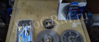
The gas distribution mechanism of the ZMZ 406 engine. First, a little theory, then we read and look at practical photos and video materials. The timing mechanism of the 406 engine is quite simple and can be easily repaired in almost any conditions and does not require special tools. Although it is VERY DESIRABLE to use a protractor for more precise adjustment. The best option is to find split gears; Master Motor used to make them, but now they seem to no longer make them. The quality of our spare parts is fantastic, it happened that I had to re-drill the marks to replace the timing chain of a gazelle 405 video camshaft stars, new chains broke after 10 thousand km. The tensioner star bearings crumbled, the balls became cubes. The stars' teeth went on vacation. All these wonderful spare parts are sold in the Rus Trade chain of stores. Therefore, you cannot save on timing. Kroilovo leads to Padalov. I will attach photos of the correct timing chains and parts. See photos and videos on replacing the ZMZ 406 timing chain below.
Typical symptoms and diagnosis. 1. The engine does not pull, sneezes 2. Dips, adjustments at speeds up to 3000 3. Problem starting 4. Popping sounds in the muffler The chain is stretched, has jumped a tooth or more. Wear of timing stars. In this case, you need to check the coincidence of the labels. You can do this as follows. Remove the valve cover.
We set the engine to TDC, focusing on the mark on the pulley and the tide on the front cover. In this case, the marks on the sprockets should be located opposite the upper plane of the cylinder head. 1. Rumble in the front part of the engine 2. A sharp tapping sound when releasing the gas 3. Noise (like a collapsed bearing) increases with increasing speed. In this case, gentlemen, drain the water and dry the oars. You can't drive a car. The chain may break (completely (in pieces)) or the star will fly off the bearing. The result may be different. On my life's journey I encountered the following: 1. Breakdown of the front cover 3500 in Rus Trade 2 Dead head 36000 in Rus Trade 3. This is just some kind of apocalypse. It broke through the front cover, the front part of the cylinder head, broke off the camshaft between the 2nd and 3rd cylinders, which pierced the valve cover through the heap and please pay attention to the HOOD. The guy said that he was driving 160. Adjustment (Replacement) of the timing belt. In addition to all the standard tools, you will also need a 6mm hexagon, NORMAL sealant ((Grey Permotex or Lockheed) remember about croylovo) and a spool of thread.
So, gentlemen, let's begin: 1. Drain the coolant and remove the radiator. 2. Remove the valve cover and the front cover of the cylinder head (hereinafter referred to as the head) 3. Unscrew the crankshaft ratchet and press the auxiliary drive belt pulley. 4.
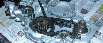
Loosen the oil pan mounting bolts, unscrew the pan mounting studs from the bottom of the front cover to remove the cover without tearing the pan gasket, and lower the pan. 5. Use a hexagon to unscrew the cover mounting bolts. From the water pump, unscrew the tube going to the heater. We unscrew the bolts of the upper and lower tensioner covers, remove the covers and take out the chain tensioners themselves. 6. Using light blows of a hammer (preferably a rubber mallet), tear off and remove the front cover, while pulling the cover down a little and toward you, trying not to tear the head gasket. We inspect and reject chains, tensioner stars and dampers. (The preferable option is “Throw it all away” (Remember about the kroilovo)) 7 gazelle We align the crankshaft to the mark (the mark is a point above the crankshaft) and install a new chain along with the intermediate gear. At the same time, do not forget to tighten the bolts.8. We install the intermediate shaft gear according to the mark, fasten the new tensioner sprockets and so that the chain is tensioned and does not sag, we tie the lower sprocket to both turns of the chain with an ordinary thread. This will help with further assembly. 9. We set the distributor. shafts according to the marks (see above), not forgetting that the leading side of the chain must be tensioned. 10. The ideal option is if you buy a protractor from someone to set the timing phases. The intake shaft should point at 22 degrees, and the exhaust shaft at 17 degrees. It is designed that when the chains wear out, the angle remains set. 11. After installing the upper chain and camshafts, insert the upper tensioner, tighten the tensioner cover and release the tensioner from the shoe side. We install the side gaskets; it is advisable to first lubricate them with sealant and let them dry a little. 12. Install the front cover where it was before. It is better to install the crankshaft oil seal after installing the cover. If we install the cover with the crankshaft oil seal, then it is necessary to carefully adjust the oil seal with some thin crap (you can use an ordinary feeler gauge) so that the oil seal spring does not fly off. 13. After installing and tightening the cover bolts, insert the lower tensioner, tighten the cover and release it. We install everything in the place where it lived before. 14. We are glad that everything is over. WHAT TO DO IF 1. The head gasket is torn. The first thought is to go shoot yourself (Hang yourself, drown yourself) and that’s right (humor joke). In fact, nothing bad happened. Take a NEW cylinder head gasket, cut off the front part (Don’t forget to remove (throw away) old one). Apply a thin layer of sealant to a piece of the gasket and the joint between the cover gasket and the head, let it dry and glue it to the block head, tying it with a thin thread. 2. After replacing the chains, the engine does not idle and there is no traction? Let’s discard the first thought immediately (see above). This means that the marks were set incorrectly, and they were off by a tooth or two on one or two camshafts at once. How to check, see even higher. 3. Does the chain break on the 406 engine? This means that the chain tensioners do not provide good tension, since there are two types, some are fixed when exiting (these are better), others are not fixed. And since the tension occurs due to oil pressure, the possible reasons are: low oil pressure, or a clogged oil supply channel to the tensioner, or a hole in the tensioner itself for oil passage is clogged. Is there a difference in the camshafts (left, right) There is no damn difference. What makes them different is the sprocket fixation pin. The only difference is in the carb and injection shafts, in terms of valve lift angle. YOU MUST REMEMBER THAT THE TENSIONER SHOE IS EVIL, install only the correct sprockets 1 – crankshaft sprocket 2 – hydraulic tensioner shoe 3 – lower hydraulic tensioner; 4 – lower chain; 5 – intermediate shaft sprocket; 6 – drive intermediate shaft sprocket; 7 – upper chain hydraulic tensioner shoe; 8 – upper hydraulic tensioner; 9– noise-insulating rubber washer; 10 – upper chain; 11 – installation mark on the sprocket; 12 – intake camshaft sprocket; 13 – mounting pins; 14 – upper chain guide; 15 — exhaust camshaft sprocket; 16 – upper plane of the cylinder head; 17 – medium chain guide; 18 – lower chain guide; M1 and M2 are installation marks on the cylinder block. Next, look at the visual instructions: The entire process of installing the ZMZ 406 timing belt begins with installing the lower chain guide, which is attached to 2 bolts. Installing the lower timing sprocket. Installing the upper timing star. This image shows how the front cover gaskets of the ZMZ gas distribution mechanism should be located. 406Installing the front cover. If the work is carried out on a machine, you can secure the chain with thread or an elastic band; it will break during the first start. There will be no harm to the engine
We install the lower hydraulic tensioner; after you screw it on, you need to unscrew the central screw and use the hole to bring the hydraulic tensioner into action. light blow with a hammer through a screwdriver, for example. Then tighten the screw back
The figure shows in what order it is necessary to tighten the cylinder head covers. Sometimes the chain does not fit correctly into the phases, then the manufacturer provides additional holes that need to be drilled. Install the right timing sprocket. The figure shows the correct timing angle
Operating principle of the clutch system
To transmit torque to the driving wheels of the vehicle from the engine crankshaft, a box is provided, because smooth transmission of torque from the motor to the wheels is unprofitable. The car will not be able to move without a clutch, and the operation of the power unit itself will be ineffective.
For comfortable operation of the power plant, the torque removed from the crankshaft must be changed in advance in the gearbox (gearbox). After which it moves to the driven axle. Since changing gears forces the gearbox gears to spin, which hit each other with force, it can be difficult to change gears. If the box is always connected to the unit, in order to completely stop the vehicle, it will be necessary to stop the motor.
Clutch operation in a Gazelle car
To solve these problems, the car is equipped with a clutch, which is a special box assembly. It promotes temporary separation of the engine and gearbox, which leads to an interruption of torque. By pressing the clutch pedal, you can change gears or stop the car. The clutch allows the car to move off smoothly and accelerate.
Read:
The principle of its operation is similar for any brand of car. It eliminates the possibility of rapid wear of components and parts that connect the power plant and the gearbox.
The clutch pressure plate, attached to the housing, presses the driven disc against the flywheel. The disk hub attached to the input shaft must be able to move freely along it. The hub body is equipped with damper springs, which act as vibration dampers and ensure smooth operation.
To make the required force when pressing, a spring with petals is provided, which are exposed to the release bearing. It is a connecting link between the drive and the clutch, onto which the fork with the lever is attached. Another lever or cable is attached to its end, leading to the clutch pedal.
Replacing the ZMZ-402 clutch fork on the Volga
Replaced early in the afternoon on a weekend
I'm
using the clutch fork
.
How to replace the clutch fork without removing the gearbox.
how to replace clutch fork
VAZ-2101-2107 cars without removing the gearbox. VKontakte groups for repairs...
Should I charge the hydraulic chain tensioner?
Should I charge the hydraulic chain tensioner?
Unread message ZVR » 09 Apr 2013, 23:28
I bought a Volga and I don’t regret it, I don’t regret anyone.
IT'S A PINK, BABY!
Re: Should I charge the hydraulic chain tensioner?
Re: Should I charge the hydraulic chain tensioner?
Unread message GAZ » April 10, 2013, 10:25
Re: Should I charge the hydraulic chain tensioner?
Unread message ZVR » Apr 10, 2013, 10:32 am
I bought a Volga and I don’t regret it, I don’t regret anyone.
IT'S A PINK, BABY!
Re: Should I charge the hydraulic chain tensioner?
GAS , I also recharged at one time. A little hemorrhagic, but possible. However, I had three cases where chains with such tensioners were thrown, and they definitely worked (mainly the upper ones), but something happened during operation, and I refused to recharge. In the end, 300 rubles. - not that much money to invest in such a rather important mechanism - a timing drive.
ZVR , there are rechargeable tensioners. But there is one nuance - you need to put the tensioner at the top a little longer. There were such people at one time, but now there are practically none left.
How to make a car starter spin in the opposite direction?
A man is designing a tractor and wants to attach an electric starter to it. The starter needs to spin in the opposite direction. He asked me to redo the starter. I understand that it is necessary to cross the ends of all four windings, but this is difficult to do, since two windings are made of a bus. Is it possible to simply change the polarity of the starter supply (swap plus and minus)? Will the starter turn in the opposite direction? In the starter, two windings are wound with a bus bar, and two with a thinner wire. And four brushes.
AK
:
swap plus and minus
Then you will have to isolate the starter casing from everything else. https://www.zaochnik.com/example.php?id=70 - a Word document is loaded, very detailed about the design of starters and switching circuits.
AK
:
The starter needs to spin in the opposite direction
. What will you do with the Bendix?
On “chisels” and “classics” the starters spin in opposite directions. Guess why? And use the one that suits you.
Changing the polarity won't do anything, you need to either swap the brushes + and - or switch the stator windings, but the work is still the same, maybe it's easier to choose a starter differently?
Mastak
, thanks, downloaded it.
Mastak
:
Then you will have to isolate the starter housing from everything else.
It looks like I figured out how to solve the problem with minimal modifications.
Only two brushes sit on the body, and everything else is isolated from the body. We isolate these two brushes from the body and supply them with plus power. It remains to check whether the starter will turn in the opposite direction when the power polarity is changed. I have already assigned this task to “Kulibin”. L0ST
:
What will you do with Bendix?
Bendix, is this a six? This is not my problem, the person who started all this is quite advanced in mechanics, he probably has it all figured out.
PS. I read the messages above. This means that changing the polarity will not give anything, but let the person check it anyway.
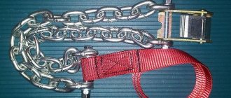
Removal and installation of hydraulic tensioners GAZelle ZMZ-406
16 The engine has 2 hydraulic tensioners of identical design - for the lower and upper chains. Sequence of actions when dismantling hydraulic tensioners: Separate the vacuum brake booster pipeline from the supply pipe. For the convenience of working with the hydraulic tensioner, we dismantle the fuel pump and move it to the side without separating the pipelines (see Removing the fuel pump). Using a “12” wrench, unscrew the 2 bolts securing the cover. ATTENTION By unscrewing the 2nd bolt, we fix the hydraulic tensioner cover by hand (it is clamped from the inside by the tensioner). Dismantle the cover. Pull out the hydraulic tensioner. Carefully pick it up with a knife, and remove the sealing gasket of the cover.. Also remove the lower hydraulic tensioner. Removing and installing hydraulic tensioners GAZelle ZMZ-406 We bring together the jaws of a vice or clamps, leaving a gap of 19 mm between them. ATTENTION Do not squeeze the tensioner body in clamps or a vice. When disassembling 2 hydraulic tensioners at the same time, do not swap their plunger pairs, as they are calibrated with a certain gap. Having secured the tensioner body in clamps, like in the mouth of a wrench, with a screwdriver with a large blade...... unscrew the valve. Pull out the spring from the base...... and the plunger in the kerosene or gasoline, we wash all parts, blow with compressed air and lubricate with engine oil. We cut out a strip from a metal sheet 0.8-1.0 mm thick (25 mm long and 10-15 mm wide). Using a mandrel or using round pliers, we compress it into a ring with a diameter similar to the plunger. We mount the plunger into the body. If necessary, use a thin screwdriver to correct the locking ring. Use a screwdriver to press down, deepening the plunger to the limit. Use the prepared mandrel to lock the thrust ring in the hydraulic tensioner body. Use the prepared mandrel to lock the thrust ring in the hydraulic tensioner body. Mount the spring in the plunger, and the body itself - in clamps or a vice, overcoming the resistance of the spring, we screw the valve into the hydraulic tensioner housing. We clamp the valve with a screwdriver, fixing the body in clamps (as during disassembly). With a correctly “filled” tensioner, the plunger is held in the body. To prevent the hydraulic tensioner from “discharging”, do not press on the protruding end of the plunger, and after installing the hydraulic tensioner in the channel of the cylinder head, do not press the tensioner itself. We set the hydraulic tensioner in a “charged” state, lubricating the channel in the cylinder head and, if necessary, replacing the damaged cover gasket. After installing the cover, we bring the hydraulic tensioner into working condition - “discharge”. To do this......using a 12mm wrench, unscrew the plug from the hydraulic tensioner cover. Using a screwdriver, press the tensioner into the hole, which, when “discharged,” will push the screwdriver out. We put the plug in its place. We also install the lower hydraulic tensioner Next page»»»»»» Loading...
Clutch fork fault detection
In this case, replace the damaged parts. If there is noticeable drag in the clutch operation, this indicates that the cylinders are not working properly or there is a hydraulic fluid leak. As in the previous case, parts are replaced. Another sign of a problem is poor pedal operation. Here, most likely the problem lies in the bearing or levers, and it can be solved by replacement.
Disassembly
After breaking, all screws can be unscrewed simply with a ratchet. Halve strictly with blows to the body. If you hit the input shaft, the impact energy will be transmitted exactly through the 4th gear synchronizer. Place all the parts in piles. If there are symptoms of hand-wringing, it would not be superfluous to take pictures of the parts before disassembling. So, let's start troubleshooting. When examining the rear oil seals, a bald spot on the second oil seal was revealed. I installed them 5 years ago:
The bushing will be discussed in more detail in the next part:
From my findings, to check wear, you can use the gearbox flange along which the release bearing slides - its diameter is exactly 38 mm, like that of the cardan fork. According to reason, there should be no free movement:
Next, remove the bearings from the shaft. They are pryed off with screwdrivers and removed without any problems:
By the way, I ended up with a box with tapered bearings, bronze nuts and synchronizers of the new standard. Formally, there was no fatal wear on the tapered bearing races (also known as the hub bearings of the front wheels), meaning shells, but the rollers were polished on the inside of the bearing:
In such a way, they were so worn out that they went so deep that their ends rested against the inner race. It shouldn't be so obvious. It is curious that the rollers themselves are also conical (10-9.3 mm).
Due to the use of high-quality semi-synthetic Rosneft GL-4, the inside of the box was completely washed with dishwashing detergent:
There were no signs of rotation in the bearing seats. The bearings themselves are simply taken out and inserted with a slight rotation:
I immediately removed the barrels for blocking the engagement of 2 gears with a magnet, because I washed the body with water and otherwise they could rust:
An overflow hole was found in the rear half of the gearbox. Thanks to him, Focus with filling the gearbox oil through the handle from the passenger compartment is likely:
Eliminating the looseness of the GAZelle gearbox lever
I think its purpose is to smooth out air pressure, because the cardan shank works like a piston pump and without damping fluctuations in air pressure by the main volume of the gearbox, the box would suck in dirt from the street:
It was not possible to knock down the main shaft bearings with a screwdriver and hammer. I used an ordinary two-legged puller, lengthening its legs with thick steel plates. There are special pullers for these purposes, but I didn’t bother to take them, it’s a very rare task and can be completely solved with a two-legged puller. On the input shaft there was an oil channel going under the bearing. What's funny, I didn't understand:
I didn’t find any wear on the shaft articulation unit, but the rollers had barrel-shaped wear - they were down by one hundred square meters in the center, and by 5 square meters on the sides. The clips themselves were without damage, and measurements with a caliper showed tolerance:
The part of the shaft entering the crankshaft also had no tangible wear:
The shift clutches were worn by several 10 mm:
The outer splines of the coupling hubs, although they were polished to a shine, did not have any tangible free play:
But the clutch hub of the 1st and 2nd gears had a small free play on the secondary shaft and was replaced:
Is it possible to mix it up and install a left-hand starter instead of a right-hand one?
All starters are different at the point of connection and there is no such thing that the starters are exactly the same, only one is left and the other is right, so erroneous installation is impossible.
A similar starter, with a different direction of rotation, will not work not only because it spins in the opposite direction, but simply because it has a different connection point. A starter can only be installed that is designed specifically for this engine.
If you just hold the starter in your hands, it is not clear in which direction it will rotate. If this is important, then you can twist the bendix with your finger. Where the bendix spins easily is the direction of rotation of the starter.
Starters are made by different manufacturers; in appearance, starters, for example BOSCH and VALEO, are noticeably different, they consist of completely different parts, but if they are intended for the same engine, then their connecting places are exactly the same, and they naturally rotate in one and the same the same side.
What are the faults of the Gazelle gearbox?
Gazelle repair may be required in some cases:
To repair a Gazelle gearbox, you must know everything about the structure of the transfer case, because disassembling the gearbox is not an easy task. This is also necessary to determine the type of failure. The most popular reason for Gazelle owners to replace the gearbox is oil leakage. It occurs due to worn out seals or bushings, worn out gaskets, as well as poor sealing of the plugs. In this case, you will need to add or change the oil in your car, as well as replace the bushing.
Formulation of the problem
Let's assume that an asynchronous single-phase motor, already connected using a starting-charging capacity, initially has a shaft rotation directed clockwise, as in the picture below.
Let's clarify the important points:
- Point A marks the beginning of the starting winding, and point B marks its end. A brown wire is connected to the starting terminal A, and a green wire is connected to the ending terminal.
- Point C marks the beginning of the working winding, and point D marks its end. A red wire is connected to the initial contact, and a blue wire is connected to the final contact.
- The direction of rotation of the rotor is indicated by arrows.
We set ourselves the task of reversing a single-phase motor without opening its housing so that the rotor begins to rotate in the other direction (in this example, against the movement of the clock hand). It can be solved in three ways. Let's take a closer look at them.
Option 2: reconnecting the starting winding
The second way to organize the reverse of a 220 Volt asynchronous motor is to swap the beginning and end of the starting winding. This is done by analogy with the first option:
- Of the four wires coming out of the motor box, find out which of them correspond to the starter winding taps.
- Initially, end B of the starting winding was connected to the beginning C of the working winding, and beginning A was connected to the starting-charging capacitor. You can reverse a single-phase motor by connecting the capacitance to terminal B, and the beginning of C to the beginning of A.
After the actions described above, we get a diagram as in the figure above: points A and B have swapped places, which means the rotor began to turn in the opposite direction.
Who pays for repairs, verification or a new meter?
The owner of the premises pays for repairs, verification, replacement with a new device, the supply of resources to which the device is metered, regardless of the location of the meter installation and access, inside the apartment or on the floor in a niche.
This is determined by the boundary between the common house property and the intra-apartment property - “a branch from the riser to the first disconnecting device” (clause 5 of the regulation of the Government of the Russian Federation of August 13, 2006 No. 491).
In this case, the call of a representative to seal the device is also paid, with the exception of cases when the device was initially put into operation or after the next verification.
Can I fix the problem myself?
The metering device has failed and this is determined based on certain requirements:
- non-display of measurement results by metering devices;
- violation of control seals and (or) verification marks;
- mechanical damage to the metering device;
- exceeding the permissible error of the meter readings;
- expiration of the verification interval for verification of metering devices.
If the meter is recognized as out of order in the prescribed manner, the owner has the right, either independently or with the involvement of employees of the service provider or other persons for a fee:
- dismantle the device;
- repair if repairs are required;
- submit it to a specialized organization for verification of the device;
- install an authorized or new device in place;
- check for leaks, including, if necessary, pressure testing the internal water supply system;
- submit an application to put the metering device into operation.
It is better to perform the work under a separate contract with the involvement of the service provider or other persons.
In the event of flooding of the apartment and neighbors, due to depressurization of the metering unit, damage can be claimed against the contractor who replaced the device during the warranty period for the quality of the work performed.
The longer the guarantee period is in the contract, the better. Attention! If you do not notify the water supplier about the malfunction of the meter and independently restore its functionality, then the violation of the integrity of the seals and the presence of mechanical damage will give the supplier the right to apply sanctions for interfering with the operation of the meter.
What if the fault was detected by the controller?
If during the next inspection the controller reveals a malfunction of the metering device, then he is obliged to draw up a report in two copies and hand over one to the owner.
The cause of the identified malfunction is of great importance. If the flow rate is not displayed, the error is significantly exceeded, or the verification period has expired, then the metering unit must be restored within a month. There should be no other consequences.
If interference with the operation of the meter is detected, in addition to restoring the metering, you will have to pay for the volume of resource calculated according to the consumption standard, taking into account the number of residents and using an increasing factor of x10. (clause 81(11) of the Rules for the provision of public utilities) for the period from the date of the last inspection of the device by the controller, but not more than 3 months.
Attention! Since January 2022, other methods for determining the volume of a resource when interfering with the operation of a meter are illegal, including calculating water based on pipe capacity.
Recommendations for extending the service life of the unit
Without proper care, the Gazelle gearbox quickly breaks down. Some explain this by the mismatch of the unit for a truck. As you know, the box used here, albeit modified, is from a passenger car. Therefore, the slightest overload or prolonged operation has an extremely negative effect on the resource. Already by the 80,000th mileage, gears begin to fly out, crackling and noise appear.
First of all, you need to change the oil correctly and promptly. The replacement interval is determined by the manufacturer at 50,000 mileage, but it is better to do this twice as often. You need to fill in not the lubricant that comes from the factory (cheap TAD 17), but higher quality analogues. For example, GL-4 or 5 with a viscosity of 75W-90.
- do not load the car above the norm of 1.5 tons;
- drive on good roads, avoiding gravel and complete off-road conditions;
- monitor the clutch, refill technical fluids on time.
The box turns off (the gear goes out)
If the speeds are off, the culprit may be the fork, clutch, or worn transmission gears. It happens that the spring that presses the fixation ball bursts. It is also possible that the input shaft splines may dry out. The reason may be the bronze crackers on the third and fourth gear forks - they break in half. It is also possible that burrs may form on the locking device.
Many defective parts are installed on the Gazelle gearbox right from the factory. For example, blocking rings, which must have a gap of at least 0.3 mm. In fact, there are many such elements with a gap of 0.1-2.5 mm.
It happens even worse when incorrect assembly is performed after repair. The unfortunate masters are capable of sorting out the crackers and springs so unsuccessfully that after a while certain gears will not turn on at all.
Breaking
- the bearings performed their functions to the end;
- lack of oil.
The second problem is much easier to solve than the first. Check the amount of oil and “add” it.
We recommend watching: how to repair a manual transmission on Gezali.
The first option requires replacement of spare parts. This is done either at the service center by specialists (if the car is under warranty, this is a big plus for the owner), or manually (but not by yourself). Only a person who understands the matter can disassemble and assemble the checkpoint. This procedure requires knowledge, patience and perseverance.
So, the first thing you need to do is drain the oil. Then remove the cardan. Mark the hinge points and the box extension, remove the clamp. Unscrew the cardan mount and remove the shank (move it backwards and remove it). The result will be a niche. Next, in the cockpit remove all the necessary parts, turn off the speedometer and light elements. After these steps, the box is removed and disconnected.
The device of the box on GAZelle Next
In order to begin disassembling the gearbox, it needs to be made clean (painstakingly washed). Disassembly is carried out step by step only by a knowledgeable person. With the slightest error, the gearbox may not work correctly on the Gazelle Next or, in general, may not show signs of life. After disassembling the box into parts, they should also be washed from traces of oil.
The cause of the strange sound is being found. It could be:
- wear of the secondary shaft bearing.
- Free running of the bearing.
- Bearing idling.
See how to replace the rear axle gearbox.
Other problems with the components may also arise. Worn and broken components are replaced with new ones.
Option 1: reconnecting the working winding
To change the direction of rotation of the motor, you can only swap the beginning and end of the working (permanently on) winding, as shown in the figure. You might think that to do this you would have to open the case, take out the winding and turn it over. There is no need to do this, because it is enough to work with the contacts from the outside:
- There should be four wires coming out of the housing. 2 of them correspond to the beginnings of the working and starting windings, and 2 to their ends. Determine which pair belongs only to the working winding.
- You will see that two lines are connected to this pair: phase and zero. With the motor turned off, reverse the phase by changing the phase from the initial winding contact to the final one, and zero - from the final to the initial one. Or vice versa.
As a result, we get a diagram where points C and D change places with each other. Now the rotor of the asynchronous motor will rotate in the other direction.
Prevention of the problem
All meters that have been in residential premises for a long time must be checked at some intervals for physical wear and tear. The regularity of such checks is based on the current state of the mechanism, as well as the deadlines specified in the passport.
In order to check the device, the consumer needs to call a specialist at the water utility and report the upcoming test. A specialist working with such devices will install it on a temporary stand and then record the readings. A temporary mechanism will be installed in its place, the readings of which will also be recorded.
Testing takes 7 – 10 days. At the end of the test, the consumer will receive a conclusion about passing the test and, if it was successful, the measuring device will be returned. And its owner will need to call a specialist again to put the original mechanism in place. He will issue a certificate, which will need to be taken to the water utility.
Related Posts
Why, when I close the air, the starter turns, but as soon as I start to take the air off, the starter goes out? The starter is new, the Akum 190 is also new, the tractor is MTZ 82.1, the capital was done last year, the hot pressure is 3.
- Author: Vadim Kutlubaev
- 25 February 15:19
- 22 comments
Guys, this is a problem: I close the air, the starter turns.
As soon as I start to bleed air, the starter goes out. What is the problem I can’t understand? The starter is new, the Akum 190 is also new, the tractor MTZ 82.1, capitalization was done that year, the pressure is on the hot 3. Why do you close the air, the Starter turns, you open it goes out, the new battery is the battery 190 MTZ MTZ 82.1 Major repairs did the Pressure on the hot 3