06.11.2019
| (Votes: 1, Rating: 5) |
Issues discussed in the material:
- What types of flywheels are installed on modern cars?
- What are the reasons for flywheel failure?
- Do I need to dismantle the gearbox when replacing the flywheel?
- How to replace the flywheel crown
- Is it possible to replace a dual-mass flywheel with a single-mass one?
At high mileage, cars with a manual transmission may experience clutch problems. Most often this is due to flywheel wear. This part can “run” without replacement for up to 200-300 thousand km and even longer. If the flywheel fails after 50-100 thousand km, you need to understand the reasons for this situation. This may be due to aggressive driving, weather conditions, or malfunction of other clutch parts. The work of replacing the flywheel is not very difficult, but will require quite a lot of time, since it will include removing and installing the gearbox and disassembling the clutch mechanism.
Flywheel for VAZ 2108-099, 2113-2115, Kalina
- Manufacturer: AvtoVAZ
- 0 reviews
- Description
- Characteristics
- Video
- Reviews 0 ? '(' + product.reviewsCount +')' : »>>
Dear customers, in order to avoid errors when sending a flywheel, please indicate the model and year of manufacture of your car in the “Comment” line.
If we consider the structure and principle of operation of the internal combustion engine, we will have to deal with such a product as the flywheel. In terms of its design, it is not anything complicated, but the functions it performs are extremely important, and it is impossible to do without it.
The engine flywheel is a component of several independent systems. Its functions include:
— reduction of vibrations when rotating the engine crankshaft. In this case, the flywheel acts as part of the engine;
— transmission of torque to the gearbox from the power unit. The flywheel is, among other things, the primary clutch disc;
— transmission of torque to the crankshaft from the starter. Through the flywheel crown, torque is supplied from the starter to spin the crankshaft and start the engine.
As an element of an internal combustion engine, this is its very first application.
1 – connecting rod journal, 2 – counterweight, 3 – flywheel with crown 4 – main journal, 5 – crankshaft.
The operation of a four-stroke internal combustion engine implies that the energy from fuel combustion appears unevenly due to the fact that this process occurs at different times in different cylinders. This supply causes a time-varying moment on the internal combustion engine shaft. To smooth out these pulsations, as well as any unevenness during crankshaft rotation, the use of a flywheel is provided, which acts as a kind of accumulator of kinetic energy.
The resulting torque is transmitted to the wheels. The flywheel is used as the clutch input shaft.
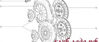
1 – flywheel, 2 – clutch assembly.
From the flywheel, the clutch receives the torque produced by the internal combustion engine, and then transmits it further to the gearbox. The flywheel plays a dual role - as the final element of the internal combustion engine, which receives the developed torque, and as part of the clutch, which receives this torque.
Flywheel when starting the internal combustion engine.
When you turn the ignition key, the relay engages the flywheel crown and the gear on the starter shaft. The starter begins to spin, the torque it creates spins the flywheel and, accordingly, the engine crankshaft. It starts, after which the flywheel crown and the starter are separated.
The most common is the solid flywheel. In fact, it is an ordinary metal disk with a crown on the end.
Other article numbers of the product and its analogues in catalogues: 21090100511501.
VAZ 2108, VAZ 2109-099, VAZ 2113-2115, VAZ 1117-1119.
Any breakdown is not the end of the world, but a completely solvable problem!
How to independently replace the VAZ 2109 flywheel on a VAZ family car.
With the AvtoAzbuka online store, repair costs will be minimal.
Just COMPARE and BE SURE.
Don't forget to share the information you find with your friends and acquaintances, because they may also need it - just click one of the social networking buttons located above.
Regular, damper flywheel and its other types
Structurally, the following types of its execution are distinguished:
- solid or regular;
- dual-mass or damper;
- lightweight.
The most common is the solid flywheel. In fact, it is an ordinary metal disk with a crown on the end.
Different car models have their own design, usually the disc diameter is thirty to forty centimeters. As an example, we can cite the VAZ 2101 disc, its weight is 6.7 kg, and the clutch diameter is two hundred mm, while for the VAZ 2110 it weighs 6.3 kg. There is no single option for any model; all VAZs, for example, such as 2112, 2114, 2110, have their own version.
Signs of a VAZ 2114 flywheel malfunction
- The clutch engages jerkily. The reason for this may be scoring on the surface of the flywheel.
- The starter works, but the crankshaft does not turn. This problem may be caused by worn flywheel teeth.
- Increased engine vibration. If the flywheel is damaged due to an accident (an extremely rare occurrence), its balance may be disrupted, causing the engine to vibrate during operation.
In these cases, the VAZ 2114 flywheel needs to be replaced.
There is another reason why owners of the “fourteenth” change the engine flywheel - tuning. In this case, to improve the dynamic characteristics of the machine, a lightweight one is installed instead of the standard engine flywheel.
Flywheel VAZ 2110 dimensions
FOR TENS ENGINES
DO NOT CONFUSE PARTS FOR TENS ENGINES
How do the engines of the VAZ 2110 family differ from the old friend VAZ 21083? It turns out, many. Read more about the differences between engines in the article by the head of the design bureau of the VAZ engine design department.
As readers already know, a new family of engines was developed for the VAZ 2110 and its modifications. It includes three basic designs: an eight-valve carburetor with the index 2110, an eight-valve with distributed injection (labeled 2111) and a 16-valve with injection (labeled 2112). All three engines are assembled on one automatic line, so they are unified in such basic parts as the crankshaft, connecting rod, piston pin, and flywheel. The need to develop new basic parts is dictated by the features of the 16-valve 2112 engine, which has significantly higher power and torque indicators compared to the 21083 engine. It has original pistons, cylinder heads and camshafts that are not unified with parts of eight-valve engines. In addition, increased demands are placed on engine reliability. The technical specifications for cars of the 2110 family established a 90 percent service life of basic engine parts with a mileage of at least 150,000 km, instead of 125,000 km for other VAZ engines.
Below we will mainly talk about the eight-valve engines 2110, 2111 and the differences between their basic parts and the parts of the 21083 engine.
Crankshaft 2112–1005015 (photo 2). In order to improve balance compared to shaft 2108 (photo 1), the counterweights have been increased. They are machined both on the side surfaces and in diameter. This allows the shaft to withstand increased loads. The shafts are unified in terms of seats, so it is possible to replace shaft 2112 with shaft 2108.
Connecting rod 2110–1004045 (photo 3) differs from connecting rod 2108 in having a more rigid lower head. The forging is original, made of material with improved mechanical properties. In the upper head there is a steel-bronze bushing (photo 4), since a floating pin is used - it can move both in the connecting rod and in the piston bosses. (Remember that in the 2108 connecting rod the piston pin is pressed into the upper head.)
Piston 2110–1004015. It differs from piston 21083 only in the presence of grooves for retaining rings in the bosses for the piston pin. Retaining rings are used from engine 21213.
The piston pin differs from the 2108 engine part in that it is reduced in length from 61 to 60.5 mm and has an internal diameter reduced from 15 to 13.5 mm.
On the engine, it is possible to completely replace all four pistons with connecting rods assemblies - 2110 to 21083 and vice versa.
Flywheel 2110–1005115 (photo 5). To transmit increased torque, the diameter of the clutch surface has been increased from 196 to 208 mm. The shape of the teeth on the flywheel ring has been changed. To reduce uneven rotation of the crankshaft, the moment of inertia of the flywheel has been increased by increasing the rim width from 20.9 to 27.5 mm. Replacing the flywheel 2110 with a 2108 is in principle possible, but at the same time you will need to install a gearbox with a starter 2108.
Cylinder block 2110–1002011. The casting is unified with block 21083; the differences are in the processing of the mounting holes. Block 2110 has additional threaded holes for the generator bracket, knock sensor and ignition module (the latter applies to an eight-valve injection engine). The cylinder block for a 16-valve engine is additionally distinguished by threaded holes for attaching the cylinder head: the thread diameter has been changed from M12 to M10.
What is the risk of crankshaft bearing failure?
Most often, after a suspicious rustling sound appears, the car will be able to travel for hundreds of kilometers. But don’t put off replacing the bearing for too long, since a seemingly trivial malfunction can turn into other problems:
- bearing destruction is the cause of increased vibration of the crankshaft, and this leads to wear of the rear oil seal and engine oil leakage;
- due to loss of support and imbalance, the input shaft shank experiences alternating loads, which may ultimately result in gearbox failure;
- the races of a jammed bearing can damage the seats on the gearbox shaft or in the crankshaft flange;
- When the separator is destroyed and the balls are lost, dismantling the outer and inner races becomes more difficult.
As you can see for yourself, you should not bring the matter to the point of complete destruction of the unit. Moreover, even a novice driver can pull the bearing out of the crankshaft.
Do-it-yourself partial repairs
All flywheels, regardless of design, have a crown in the form of teeth, which is involved in transmitting force from the starter when starting the engine. It is made of steel and is structurally pressed onto the body of a cast iron flywheel. If the teeth wear out or cracks appear, the crown must be replaced. This operation is justified by the fact that the price of a new product is 5-6 times higher than the cost of the crown. The process of self-replacement is quite complex and consists of the following steps:
1. The removed flywheel is placed on a reliable base, and uniform blows are applied along the entire perimeter. In most cases, the crown moves and falls off. If this cannot be done with a chisel, the part is preheated.
2. Heating the flywheel crown to increase its diameter due to thermal expansion. To do this, the part is placed for 25-30 minutes in an oven with a temperature of about 250 o C, or if it is not available, 3-4 supports are prepared, a crown is placed on them, a rag soaked in solarium is hung along the diameter and set on fire. When heating, it is unacceptable to heat the crown red-hot, and it is also undesirable to expose it to direct fire from a fire or gas stove.
3. After warming up, quickly, but without fuss, transfer the part to the flywheel, on which it should immediately sit. If necessary, alignment accuracy is achieved by using a hammer.
4. After complete cooling, the repaired flywheel is ready for installation on the engine.
If the front part of the ring is worn by the starter teeth and there is no other damage, there is no need to replace the entire ring. It is enough to turn it over to the other side.
Replacing the flywheel crown
will be carried out in case of wear and tear, usually during engine repairs or in emergency conditions. The flywheel crown serves to rotate the crankshaft during starter operation.
When the starter is turned on, its drive gear engages with the teeth of the flywheel ring, rigidly mounted on the crankshaft and sets it in motion.
The teeth on the starter drive are beveled to fit easily between the flywheel ring teeth. When the bevel of the tooth on the starter gear is clogged, the gear cannot get into the teeth of the flywheel and, while rotating, begins to cause nicks on the crown and there comes a moment when the teeth cannot engage at all, since the teeth on the flywheel crown have reached their maximum wear.
This is easy to verify if you remove the starter and look at the flywheel crown, where you can see worn teeth when turning. On some models (VAZ -2108 and their modifications), wear can be seen through the window used for setting marks.
Chainsaw starter repair
During frequent use, some components of the chainsaw may be subject to constant dynamic influences, which is why, for example, at the most inopportune moment the cable may burst, the shaft will begin to rotate at a much lower speed, or the teeth of the ratchet will crumble. Taking this into account, repair and inspection of a chainsaw starter can be an operation that is carried out more than once during one working season!
Spring repair
If the quality of the spring material is poor, the latter tends to burst, and usually the rupture occurs at the site of contact with the drum, in the place where a loop is formed
In this case, it is not necessary to change the spring at all! It is quite enough to simply thoroughly clean the surface of existing grease and dirt, and then carefully sand the damaged area. At the end, the spring is released at a temperature of 600-650 degrees until the steel gets a crimson tint. The part should cool gradually, where at 100-150 degrees it is already possible to carefully wrap the end of the spring on the inner surface of the drum according to the shape of the limiting protrusion so that the material obtains the desired plasticity
In this case, the elastic characteristics of the spring will remain the same
The part should cool gradually, where at 100-150 degrees you can carefully wrap the end of the spring on the inner surface of the drum according to the shape of the limiting protrusion so that the material obtains the desired plasticity. In this case, the elastic characteristics of the spring will remain the same
Replacing the cord
If the cord is pulled, the cable begins to rub against the starter housing. Replacing the cord begins with disassembling the unit body, during which the ratchet drum is carefully lifted so that the return spring does not slip from its socket. It is more correct and more convenient to do this together, where the second one will hold the spring while replacing the cable! After the cable is successfully fixed in the grooves of the drum and the handle, it is wound onto the roller, followed by the assembly of the housing.
Dual mass flywheel, operating principle
However, this is often not the best flywheel option used on a vehicle. The fact is that the internal combustion engine operates unevenly, in addition, driving modes are constantly changing (acceleration, deceleration), which leads to additional loads on the crankshaft. Let there be the simplest situation - the car moves uniformly and straight. The road is clearing ahead, let’s assume that the tractor has turned to the side, having gained free space, the driver begins to accelerate.
This creates several additional sources of load. The unevenness of the fuel ignition processes leads to the fact that the crankshaft also rotates unevenly. It is partially smoothed out by the flywheel. But there is one more feature - when the car accelerates, the crankshaft spins at a higher frequency than before.
For the shaft, it exceeds the frequency of rotation of the flywheel; the shaft has already spun, but the flywheel, due to its inertia, has not, as a result of which additional loads arise, the so-called “torsional vibrations”. They are transmitted to the transmission, resulting in additional knocking, vibration in the gearbox and other similar gifts. A way out of this situation may be to use a dual-mass flywheel.
What kind of device is this that allows you to achieve excellent results? The dual-mass flywheel is shown in the photo; in fact, it consists of two disks connected by springs.
The design of a particular dual-mass device may differ from that shown above. In any case, these are two disks connected by a bearing. The first disk is mounted on the crankshaft, and there is a ring on it for connecting the starter, the second is connected to the clutch. A spring damper system is installed between the discs. The disks have the ability to rotate relative to each other, while the springs dampen jerks and various vibrations that occur during operation of the internal combustion engine.
However, not everything is good, in any case, the dual-mass flywheel cannot boast of widespread use, for example, like a regular VAZ 2108 flywheel.
And the whole point is that when driving at low speeds, especially on cars with diesel engines, which have increased torque, the unevenness of fuel ignition is maximum. The consequence of movement in this mode will be the occurrence of significant torsional vibrations, leading to an increased level of load on the damper springs. As a result, the dual-mass flywheel fails. It is worth noting that in addition to the dual-mass flywheel, there are other types of it, but this is a topic for another discussion.
What is used in VAZ cars?
It is not surprising that for VAZ cars, for example, such as 2112, 2114, 2110, as already noted, a variety of flywheels are used. In cars of this family, a conventional flywheel is used, not a dual-mass flywheel. True, for the representative of each VAZ family it is different, differing in the weight and size of the clutch disc.
So, all VAZ classics are equipped with a flywheel from 2101, Niva and Chevy Niva - from 21213. Eights are equipped with products from 2109. Tens, Kalinas, Priors, Grants use a flywheel from VAZ 2110. All types of flywheels, from VAZ of various families, for example such , like 2112, 2114, 2110, are distinguished by different seats, outer diameters and crowns.
The role and importance of the flywheel in an internal combustion engine is difficult to overestimate, and probably simply impossible. It is this that smoothes out jerks, creates normal conditions for the operation of the transmission and reduces vibration from the engine transmitted to the body. In order to increase its efficiency, various designs are used, although often the design in the form of a conventional disk works quite successfully in the engine.
What else is worth reading
VAZ 2103 engine design
VAZ 2112 generator device
How to decipher tire markings
Cause of knocking noise in front suspension
Lightening the flywheel
General concept of the flywheel
ATTENTION! A completely simple way to reduce fuel consumption has been found! Don't believe me? An auto mechanic with 15 years of experience also didn’t believe it until he tried it. And now he saves 35,000 rubles a year on gasoline! Read more"
The part of the car engine that is designed to regulate the supply of energy is called the flywheel. It is thanks to this unit that the accumulation of energy is ensured with a greater supply of rotational motion.
So, a flywheel in a modern car is needed in order to:
- start the internal combustion engine;
- connect the internal combustion engine to the gearbox and transfer the CM from the engine to the gearbox;
- regulate crankshaft rotation.
Flywheel VAZ 2106. Removal, installation and troubleshooting.
The flywheel from a VAZ 2106 car is removed for replacement or repair if the ring gear is damaged or if the friction surface is damaged or severely worn.
The flywheel is installed at the rear end of the crankshaft and secured to it with six bolts: 1 - ring gear; 2 — fastening bolt; a is the friction surface. You will need: a screwdriver, a 17mm socket wrench, a torque wrench. 1. Remove the gearbox from the VAZ 2106 (see section 5 “Transmission of the VAZ 2106”).
2. Remove the clutch housing with the pressure plate and the driven clutch disk from the flywheel (see section 5 “Transmission of a VAZ 2106”). 3. Screw the bolt into the lower left threaded hole of the clutch housing mount, secure the flywheel from turning by resting the screwdriver against the ring gear and resting it on the installed bolt and bipod of the steering mechanism, and unscrew the six bolts securing the flywheel.
4. Remove the support washer while holding the flywheel. 5. Remove the flywheel. 6. Check the condition of the ring gear; If the teeth are damaged, replace the flywheel. 7. The surfaces of the flywheel mating with the crankshaft and the clutch driven disc must be free of scratches, burrs and completely flat. If there are scratches on the working surface 3 of the flywheel under the clutch driven disc, grind this surface, removing a layer of metal no more than 1 mm thick. Then grind surface 2, maintaining the dimension (0.5+0.1) mm and ensuring parallelism of surfaces 2 and 3 relative to surface 1. The tolerance for non-parallelism is 0.1 mm. After grooving, install the flywheel on the mandrel, centering it along the mounting hole with the emphasis on surface 1, check the runout of planes 3 and 2. At the extreme points, the indicator should not show runouts exceeding 0.1 mm.
8. Install the flywheel and the removed components and parts on the VAZ 2106 car in the reverse order of removal. The flywheel can be installed on the crankshaft in two opposite positions, determined by the location of the mounting holes. However, at the factory it is balanced together with the crankshaft, so it must be installed strictly in its original position. For correct installation, a mark is made on the flywheel
in the form of a conical hole, which should be oriented when installed in the same direction as the connecting rod journal of the fourth (first) cylinder. If the crankshaft was turned after removing the flywheel, set the piston of the fourth cylinder to the TDC position of the compression stroke (see “Installing the piston of the fourth cylinder to the TDC position of the compression stroke”). and install the flywheel on the crankshaft, turning it with mark a
vertically up. Tighten the flywheel mounting bolts evenly crosswise with the torque given in Appendix 1. “Tightening torques for threaded connections of VAZ 2106”
Removal, installation and troubleshooting of the flywheel on VAZ 2108, VAZ 2109, VAZ 21099 cars
Procedure for bearing replacement
To get to the faulty unit, you will have to remove the gearbox, clutch and flywheel. Carry out similar work on a lift, pit or overpass, using a special crankshaft bearing puller (a device for pressing out of blind holes).
Crankshaft bearing puller
The replacement procedure is as follows:
1.First, disassemble the crankshaft bearing removal tool into its component parts, otherwise you will damage the thread when installing it. After this, lubricate the conical protrusion on the puller bushing with engine oil or grease - this will protect its surface from damage.
2.Install the press-out spacer sleeve into the inner race of the bearing and drive the device in until it stops.
3.To remove the bearing from the crankshaft, do the following. First tighten the puller screw by hand. Then, holding the press-out sleeve from turning with a 14-point open-end wrench, tighten the screw with a 17-point socket. Resting against the blank wall of the hole in the crankshaft flange, the shank of the device moves out of the coupling, pushing it along with the bearing out of the socket.
4. Having removed the damaged part, wipe the seat in the crankshaft from dust and lubricate it with engine oil. Don’t forget to check and, if necessary, replenish the amount of lubricant in the new bearing - manufacturers often sin with excessive efficiency.
Tooth - crown - flywheel
As a result of wear, the teeth of the flywheel rims should not have a length of less than 15 mm in the ZIS-120 and 7 mm in the GAZ-51. If the length of the teeth is less than 18 mm, it is allowed to repress the crown with the reverse side. Before pressing, the ring gear is heated to 400 C and pressed onto the flywheel, ensuring tension in the range of 0 30 - 0 97 mm in ZIS-120 and 0 39 - 0 64 mm. Nicks, burrs and breaks of no more than two teeth (not located nearby) are cleaned with a personal file.
If the gear teeth rest against the teeth of the flywheel ring, then drum 14, continuing to move driver 15, will rotate the gear along the thread, and engagement will be achieved.
If the gear teeth abut the flywheel ring teeth, the relay armature continues to move due to compression of the buffer spring 6 and closes the power contacts of the traction relay. The armature of the electric motor with the drive rotates and the drive gear, under the action of the buffer spring, engages when its tooth is installed against the cavity of the flywheel ring gear. The use of additional force in the splined coupling of the shaft and the guide sleeve of the clutch drive race to move the gear makes it possible to reduce the traction force and stroke of the electromagnet armature, the size and weight of the traction relay.
However, there may be cases when a tooth on the starter gear hits a tooth on the flywheel ring.
The adjustment of the engagement moment of the drive gear is incorrect, the starter is installed skewed, there are nicks on the ends of the flywheel ring teeth.
| Starter drive and freewheel. |
If, when the starter is turned on, its armature rotates at a high frequency, but the gear does not engage with the flywheel ring gear, then you need to check and clean the flywheel ring teeth with a file or adjust the stroke of the starter drive gear in the sequence specified in the manufacturer's instructions.
Some car models are not known to be equipped with a device that prevents the starter from being engaged incorrectly while the engine is running. The operation of such a machine is associated with a constant risk of breaking the teeth of the flywheel and starter. The proposed device protects the engine from possible damage and, in addition, indicates to the driver an unexpected engine stop.
The screw splines on the starter shaft, through which rotation is transmitted from the armature shaft to the freewheel, help shift the starter gear 17 until it stops against the limit washer 18, ensuring full engagement of the teeth of the gear 17 and the flywheel ring gear. To make it easier to turn on the starter, the teeth of gear 17 are beveled. However, there may be cases when a tooth on the starter gear hits a tooth on the flywheel ring. Then the fork 21 continues to move the driving clutch 14, located between the springs 13 and 75, due to the compression of the spring 15, which allows the contact plate 26 to close contacts 1 and turn on the starter.
| Block diagram of the IMD-2M power meter. |
If there is no such hole, it is made with the condition that the sensor is installed correctly. When the flywheel rotates, sinusoidal current pulses are excited in the inductive sensor. The pulse frequency is equal to the crankshaft rotation speed per second multiplied by the number of flywheel teeth. The pulses are fed into the forming device, where they are amplified, converted from sinusoidal to rectangular, and transmitted to the calculation and control unit.
The duration of one start should be no more than 20 s. It is recommended to repeat the start if the engine does not start running steadily after 20 s. Before restarting, you should wait 1 - 2 minutes for the starter armature with the gear to finally stop, since the teeth of the flywheel ring and starter gear may break. After starting the engine, it is necessary to check its operation in all modes. An engine that has been running under heavy load should not be stopped immediately; it should run for approximately 2 minutes at low engine speed with the engine idling, and only then can the ignition be turned off.