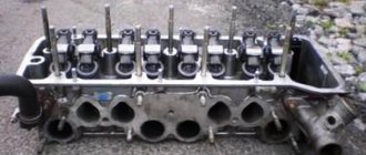
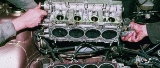
As you know, the engine cylinder block is the basis of any internal combustion engine. In fact, the block is a three-dimensional part, inside of which various components and mechanisms are located (pistons and rings, as well as CPG liners, crankshaft, crankshaft connecting rods, etc.).
Also, a cylinder head is installed on the cylinder block through a gasket, which is a “continuation” of the block. The timing belt is located in the cylinder head. At the same time, both the components inside the block and in the cylinder head are subject to significant mechanical and thermal loads during engine operation.
It is not surprising that damage to the cylinder block will not only impair performance, but will also disable the power unit. For this reason, the restoration of the unit and its repair must be carried out efficiently and in a timely manner.
In what cases does the cylinder head need repair?
In principle, anything can happen to the cylinder head, from the breakdown of small parts to the appearance of cracks in the structure of the head itself. But we will not consider all these nuances, but will focus on the most typical breakdowns of large components and elements.
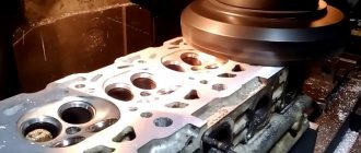
The process of grinding the cylinder head assembly
There are several reasons why the cylinder head breaks and, accordingly, repairs.
What are they:
- regular driving with an overheated engine;
- malfunction and breakdowns in the internal combustion engine lubrication system (meaning low-quality motor fluid, antifreeze or fuel getting into the oil);
- wear of components as a result of spent service life.
Sorry, there are no surveys available at this time.
In what cases is cylinder head repair necessary?
- Failure of the camshaft or other components associated with this assembly.
- Failure of guide bushings.
- Breakage of cast iron cylinder blocks and cracks in the head. In this case, the repair process at home is carried out only if you have welding equipment and know how to use it.
- Replacing the cylinders themselves. Scores, cracks may appear on them, or the cylinders may simply have “outlived” their useful life.
- Broken valves or connecting rod. Such cylinder head failures may subsequently cause the need for major engine repairs.
- The appearance of cracks in the sleeve. Typically, this problem occurs in cases where a motorist or a mechanic at a service station has incorrectly tightened the head mounting screws.
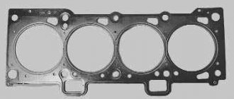
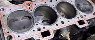
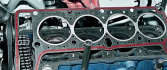
- Broken gasket. It is also one of the most common breakdowns. Usually wears out due to spent service life.
Actually, this is only a small part of the reasons why it is necessary to remove the cylinder head and repair it. We will describe in more detail below the most common fault repair methods.
This is interesting: Oil scraper rings - eliminating problems in cylinders
Causes of wear
When fuel burns in the combustion chamber, gases enter the grooves of the piston rings and force them against the cylinder surface. The pressure force decreases as the piston moves downward. Therefore, the cylinders wear out more at the top than at the bottom. As for lubrication, it is worse in the upper part of the cylinders due to exposure to high temperatures. The force that acts on the piston in an engine during its power stroke is divided into two important components.
The first part of this force is directed along the connecting rods. The second part is directed perpendicular to the axis of the cylinders. She presses the pistons against the left side of the wall. When compression is transmitted from the crankshaft to the connecting rod, the force is also split into two parts - one works along the connecting rods and compresses the fuel mixture, and the second presses the piston against the right wall of the cylinders. Lateral forces also work on the intake and exhaust strokes, but to a much lesser extent.
As a result of the action of lateral forces, the cylinders wear out in the plane of operation of the connecting rod and ovality occurs. The wear on the left wall is more significant, since the lateral force during the working strokes of the pistons is the highest.
In addition to the formation of ovality, the action of lateral forces also causes taper. As the piston moves downward, the effect of lateral forces decreases.
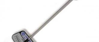
Scoring on the cylinder walls is formed due to overheating, oil starvation, oil contamination, insufficient clearances between the cylinder walls and the piston, poorly secured piston pins, and due to broken piston rings. How badly the cylinder is worn can be determined using an indicator or bore gauge.
Repair manual
Any repair manual for this unit implies its dismantling and installation. If you don’t know how to remove the cylinder head, you can read about it in more detail. You can find out about all other repair methods below.
Replacing cylinder head valves
According to statistics, the procedure for desiccation and replacement of valves is most often carried out on old domestic cars and foreign cars. But it is also relevant for newer cars, both Russian and foreign made. To do this, you must know, at a minimum, how the cylinder head is removed and installed. To do desiccant, you should buy a special device, which is called a desiccant. It may have a different design for a specific machine model.
If you don’t have a desiccant, you can use a regular metal tube. The diameter of the pipe should be about 2 cm. The valve should be supported in the combustion chamber. Place the BC head on the floor. Then place the tube on the top of the valve and hit it with a hammer. By hitting it several times, the so-called crackers will crumble and release the spring. The springs are dismantled, after which the valves themselves are removed. Their replacement and installation occurs in the reverse order.
Replacing bushings
To install new bushings you will need:
- mandrel for installation;
- lubricant (you can use regular motor oil);
- hammer.
The cylinder head is installed on a stand, and the bushings are lubricated with grease. It is advisable to heat the cylinder head to 100 degrees; for this you can use an electric stove. To make the bushings fit even easier, you can place them in the freezer for thirty minutes (before greasing them with oil). When all the bushings have been replaced, you need to wait some time until the head cools down. It is necessary that the valves do not dangle, but also do not stick, otherwise repairing the cylinder head will be useless.
Valve lapping
If you already know how to remove and install the cylinder head, then the final stage of the repair will be grinding in the valves and checking the tightness of the gasket. After replacing these elements, their grinding is done so that these elements fit most tightly to the seats.
You will need to purchase a lapping paste, then use this substance to treat the valve on all sides. After this, the valve is installed in the head.
Then the valve will need to be rotated; for this you can use one of the most current methods.
- The first method is the old one. You can use a piece of hose that should fit the diameter of the valve. The hose is clamped between the palms and rotates first in one direction, then in the other, alternately. This method is not particularly convenient, because it was relevant at least 30 years ago.
- Modern method. To facilitate this process, you can use a special device for grinding in the element, available at any automotive store. This will make lapping the valve much easier.
To understand that the valve has been sufficiently ground in, it is necessary to visually evaluate the surface of the installation site and the end part of the valve. It should be matte and continuous.
Experts do not recommend doing such things if you don’t know how to do it correctly, because you can grind it in and assemble it, but it doesn’t work, and you’ll have to change the valve seats. And when disassembled, it turns out that it was only necessary to cut and grind.
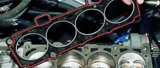
As for the tightness of the cylinder head, after replacing the gasket, attention should also be paid to this point. Leaks are checked by pouring kerosene or fuel into the intake and exhaust manifolds. If everything is done efficiently, then within 5-7 minutes no liquid will flow out from under the cylinder head valves, this is an indicator.
Repairing cracks in cylinders and water jackets
Cracks on the cylinder walls and water jacket are the result of freezing water in the block, pouring cold water into an overheated engine, careless handling of the block during repairs, or pressing the liners with too much interference.
The presence of cracks on the cylinder wall is accompanied by water entering it, which entails interruptions in engine operation and a drop in power. If there are cracks on the wall of the water jacket, water leaks along the outer surface of the engine. Cracks can be detected by testing the cylinders and jacket with tinted water under pressure for 1-2 hours. The cylinders are tested under a pressure of 20-25 atm, and the water jacket - under a pressure of 2-3 atm.
The location and size of the crack is determined by the deposition of the dye.
Sometimes it is possible to determine the presence of a crack in a simpler way. To do this, the intended location of the crack is moistened with kerosene, and then wiped dry and sprinkled with dry chalk powder. After 1-2 hours, kerosene that has penetrated into the crack will come to the surface and give a distinct yellow stripe, by which it is easy to determine the presence and boundaries of the crack.
Cylinder cracks are eliminated by installing liners or gas welding on the water jacket side (for this, a piece of the water jacket wall is specially cut out opposite the cylinder crack); at the same time, the entire cylinder block is heated on charcoal.
The welding operation is complex and responsible and is therefore rarely used.
Cracks in the water jacket are repaired by pinning, patching, metallization, putty, and less often by welding.
Pinning is done in the following order:
- Drill the ends of the crack with a 4.8 mm drill and drill holes along the entire length of the crack at a distance of 8 mm.
- Cut the threads in the holes with a 6 mm tap, then wrap red copper rods into the holes and cut them with a hacksaw so that they protrude by 1.5-2 mm.
- Drill holes in the middle between the rods and cut threads into them, then screw in the rods, which should capture the ones screwed in earlier.
- apply a patch to the crack, lightly tap it into place, using the patch as a template, punch it, drill holes in the block with a 4.8 mm drill and cut threads into them with a 6 mm tap;
- lubricate the patch with red lead, put it in place and screw it with steel screws; when applying a patch to the block head, you need to install a lead gasket under the patch;
- stamp out the edges of the patch and test the block with water under a pressure of 2-3 atm.
Metallization seals small cracks, which are first cut with a cross-section, degreased, and then metallized using a metallizer.
Only small cracks are sealed with putty, and putty of the appropriate composition is applied to the prepared crack for 1-2 hours. dried. Preparing a crack involves cleaning it and degreasing it.
Small hairline cracks can be filled with hydrochloric acid mixed with ammonia; in this case, the crack is healed by deposited rust.
The crack is welded in the following order:
- package the crack to obtain a bevel of the walls at an angle of 45°;
- slowly heat the block to a temperature of 650-700° in a thermal oven;
- the heated block is covered with sheet asbestos, leaving only the welding points open;
- weld cracks with cast iron electrodes;
- place the block in the oven and cool it slowly (6-8 hours);
- The seam is machined, then the block is tested with water.
Diagnostics of engine cylinder liners consists of correct defect detection of cylinder liners.
- It is necessary to carry out an external inspection using a magnifying glass. The purpose of the external inspection is to identify cracks, scratches, rust, scale, and scuffing of engine cylinder liners . Conduct an analysis and compile a description of defects with their location and justified reason for their occurrence.
- We determine the amount of wear of the upper and lower seating flanges of the cylinder liners . To measure the wear of the seating belts of cylinder liners, use a micrometer, measuring the diameters of the upper and lower belts of 4-5 cylinder liners. Measurements are carried out in two mutually perpendicular directions (parallel and perpendicular to the axis of the crankshaft).
After carrying out the above measurements, the results obtained are compared with established standards and a conclusion is made about the technical condition of the seating belts of the cylinder liners and methods for repairing the engine cylinder liners .
- We determine the wear pattern of the cylinder liner hole by measuring the diameter of the hole with an indicator bore gauge in two mutually perpendicular directions (parallel and perpendicular to the axis of the crankshaft) in six planes.
To increase measurement accuracy, take several measurements of the hole in one sleeve.
Cylinder liner bore diameter measurement diagram
a – measurement planes; b – expected wear pattern. The nature of wear on the working surface of the cylinder liner is due to increased wear in the area of the upper position of the first compression ring due to friction under conditions of insufficient lubricant, high temperatures and pressures. This value determines the value of the nearest repair size assigned when restoring engine cylinder liners, in accordance with the current repair specifications. When completing the defect detection of cylinder liners, measure the hole diameter of five cylinder liners in the upper and lower parts at a distance of 20 mm from the edge in two mutually perpendicular directions (parallel and perpendicular to the axis of the crankshaft).
Sources:
- krutimotor.ru
- xn—-itbachmidudk6msa.xn--p1ai
- krutimotor.ru
- www.autoezda.com
Valve seat repair
Rice. Valve seat milling sequence.
Slight wear of the valve seat can be eliminated by grinding the valve into it. In case of significant wear, the valve seat is milled with cone cutters, first with a roughing cutter with an angle of 45° (the exhaust valve seat of the ZIS-120 engine is milled with a milling cutter with an angle of 30°), then with a cutter with an angle of 75° (the lower chamfer is removed) and finally with a cutter with an angle 15° (remove the top chamfer). After this, the seat is finally processed with a finishing cutter with an angle of 45°.
Rice. Valve seat grinding.
Milling can only be done if the valve guides are slightly worn or they are new and ensure a tight fit of the cutter rod. When milling, do not remove excess metal layer so as not to reduce the service life of the seat.
Rice. Boring the valve seat with an end mill.
After milling, the seat is ground with a cone stone using an electric drill and the valve is ground in. If the seat is worn heavily or after repeated milling, when the upper edge of the valve head drops below the edge of the seat by 0.5 mm, the seat is bored on a drilling machine with an end mill and a cast iron ring is pressed into it with an interference fit of 0.12-0.2 mm, which is then processed with conical cutters in the sequence indicated above. If the block provides for the installation of replaceable seats, then the worn seat is replaced with a new repair size.
Rice. Puller for pressing out the valve seat insert: 1 - puller body; 2 - tension nut; 3 — support washer; 4 — screw with an expanding cone; 5 - nut, on the axes of which there are three levers; 6 — lever spring; 7 — expansion cone of levers; 8 — puller lever.
To replace the valve seat:
- Press the worn seat out of the block using a special puller; install the puller into the saddle so that its levers are below the annular belt of the saddle; then tighten the expansion cone screw and press out the seat using the tension nut.
- Bore the seat in the block with an end mill, taking into account the fit of the seat with an interference fit of 0.12-0.2 mm.
- Press in a new saddle and hammer out its edges with a mandrel.
- Grind the seat and grind the valve to it.
Rice. Mandrel for hammering out the valve seat insert.
Factories produce seats of repair sizes with an outer diameter increased by 0.05 and 0.25 mm for GAZ-51 and M-20 Pobeda engines and by 0.5 mm for the Moskvich car engine.
Descaling
Scale in the water jacket impairs engine cooling, causing overheating and loss of power. To remove scale, all round holes in the water jacket are closed with wooden plugs, and plates with rubber gaskets are screwed to the shaped holes. Then a solution of the following composition is poured into the shirt:
- Caustic soda: 50 g.
- Kerosene: 10 g.
- Water: 1 l.
After 6-8 hours. the solution is released and the shirt is washed with water.
Blocks with aluminum heads (M-20 Pobeda, GAZ-51 cars) are washed with a 3% nm solution of hydrochloric acid, which is poured in for 30-40 minutes; After this, the solution is released and the cylinder jacket is washed with clean water.
Repair of valve guides
Worn valve guides are restored by reaming them with an extended reamer to fit the increased repair size of the valve stem. If the bushings are significantly worn, they are removed under a press or drift and replaced with new ones. The new bushing is pressed into the block with an interference fit of 0.03 mm, and then its internal diameter is expanded to the nominal size or to a reduced one, so that old valves with ground stems can be used.
Rice. Removing the valve sleeve using a drift.
This is interesting: Repairing fuel equipment for diesel engines - is it a big hassle?
Cylinder block design
Inside the block there are through holes with polished walls, inside which the pistons move. In the lower part there is a special bed on which the ends of the crankshaft are fixed using bearings. There is also a surface intended for fastening the pan, together with which it forms a crankcase for the lubricant.
The upper part of the block has a perfectly flat surface, to which the cylinder head is attached with bolts. What everyone is now accustomed to calling cylinders are formed from the head and the block itself. On the side, the block has special brackets for attaching to the car body.
Inside the cylinders there may be special liners that are pressed inside using special mechanisms. Liners are widely used in cylinder blocks made of aluminum.
All parts that are attached to the engine have special sealing gaskets that prevent oil leakage through the joints. When repairing the cylinder head, it is recommended to replace all these gaskets.
Defect in the inner surface of the liner
When operating a vehicle on dusty roads and in industrial cities, dust particles enter the internal combustion engine cylinders through the air filter or leaky air duct connections, as well as with dirty fuel and poorly filtered engine oil.
The result is an impact on the sleeve mirror with the effect of sandpaper (scratches and nicks on the sleeve mirror). Over time, the scratches become more numerous, and then the tightness of the fit of the piston rings to the mirror wall of the liner critically decreases, which leads to a drop in compression in the cylinder.
It is possible to restore the mirror of the inner surface of the liner using the chrome plating method, and in cases of critical wear on the surface of the liner, which cannot be eliminated by this method, the damaged liner will need to be replaced.
In order to prevent abrasive from entering the internal combustion engine cylinders, the car owner must carry out maintenance in accordance with strictly defined regulations. When carrying out maintenance, you need to focus on checking the tightness of air duct connections, and also use oils and filters recommended by the manufacturer.
[custom_ads_shortcode3]