A car's axle shaft (drive shaft, drive) is a special shaft through which torque is transmitted from the internal combustion engine to the drive wheels. The axle shaft (drive axle shaft) allows you to create moving contact and effectively transmit force, while maintaining the ability to turn the wheels. The axle shaft also reduces vibrations and takes on various loads (gravity, traction, braking force, bending moments, etc.).
Structurally, two joints (CV joints) are attached to the axle shaft, which allow uniform transmission of torque regardless of the position of the wheels and suspension parts. As a result, vibrations on the steering wheel are reduced, the car moves smoothly, and power losses from the engine to the wheels are minimized.
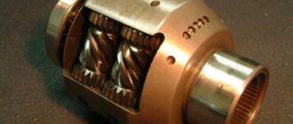
Half shaft
A car's axle shaft (drive shaft, drive) is a special shaft through which torque is transmitted from the internal combustion engine to the drive wheels. The axle shaft (drive axle shaft) allows you to create moving contact and effectively transmit force, while maintaining the ability to turn the wheels. The axle shaft also reduces vibrations and takes on various loads (gravity, traction, braking force, bending moments, etc.).
Structurally, two joints (CV joints) are attached to the axle shaft, which allow uniform transmission of torque regardless of the position of the wheels and suspension parts. As a result, vibrations on the steering wheel are reduced, the car moves smoothly, and power losses from the engine to the wheels are minimized.
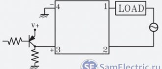
How does the differential work?
Schematic diagram of the differential
The unit operates as a planetary gearbox. The basic structure of the differential: the gears of the axle shafts (5) and satellites (4) are located in the cup (3). The cup (housing) is rigidly connected to the driven gear (2), which receives torque from the main gear drive gear (1). The housing transmits rotation through satellites to axle shafts that rotate the drive wheels. Different angular velocities are provided due to the operation of the satellites. The amount of torque remains unchanged.
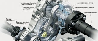
Vehicle axle structure
The overall design includes 3 main elements:
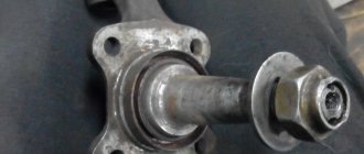
In fact, the axle shaft is a shaft of one length or another (depending on the characteristics of the vehicle). Adapters for installing CV joints are attached (welded) to the shaft.
In order to prevent twisting, the connections are splined. At the end of the adapter, the shaft is secured with a retaining ring, which prevents the shaft from accidentally coming out of the CV joint.
The inner CV joint is responsible for moving the wheel during vertical movement of the suspension, while the outer one is responsible for turning the wheel.
If we talk about the types of axle shafts of a car, axle shafts according to types and types are divided into:
The unloaded axle shaft is installed on trucks, buses, etc. In this case, the axle shaft stands inside the bridge, and the wheel hub rests on the bridge beam with two bearings.
This design means that the bending moment is borne by the bearings, and the only task of the axle shaft is to transmit torque. It turns out that such an axle shaft does not experience additional loads compared to a half-loaded one.
Self-diagnosis methods
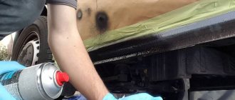
On a level surface, the car is placed on the parking brake, the rear wheels are blocked with wheel chocks or auxiliary objects.
Using a jack and two supports, the front of the car is hung so that the drive wheels do not touch the ground.
The engine starts, first gear is engaged (for automatic transmission – mode D). If, when the front wheels rotate slowly, a sharp metallic crack or crunch is periodically heard, then the inner CV joints are faulty. It is in this way that the condition of the internal hinges is determined at service stations by lifting the car on a lift.
Additionally, it is worth inspecting the anthers for damage and lubricant leakage, and also checking for play in the structure. To do this, shake the drive in different directions, preventing the axle shaft from turning.
Warning! A faulty inner CV joint can fall apart or jump out of the transmission at high speeds and cause a serious accident. It is necessary to promptly diagnose and eliminate identified drive defects.
Common axle shaft malfunctions and causes of breakdowns
It is important to understand that the axle shafts (especially in the case of passenger cars) bear quite large loads. Moreover, such loads increase significantly if the car is operated in off-road conditions, the driver often makes sharp turns at high speed while driving, practices sharp starts with the wheels turned out, etc.
Taking into account the above, it is recommended to constantly monitor the condition of the CV joint boots, check the joints for play, etc., since spline joints may become unusable during long-term operation.
If repairs and replacement of worn-out elements are carried out, it is necessary to purchase parts and spare parts of proper quality. The fact is that the use of non-original cheap substitutes can lead not only to the rapid failure of such a spare part, but also cause an accident.
Correct gear shifting in a car with a manual transmission: when to engage a particular gear on a manual transmission, working with the clutch pedal, errors.
Gearbox differential: what is it, differential design, types of differentials. How does a gearbox differential work in a car transmission?
Gears are difficult to engage or speeds on a manual transmission do not engage: the main causes of the malfunction and possible problems.
The design and principle of operation of a manual gearbox. Types of mechanical boxes (double-shaft, three-shaft), features, differences
Connection between the gearbox and the car engine. Connecting a manual and automatic transmission with an internal combustion engine: what to look for, features and nuances.
What is a gearbox in a car: the purpose of the gearbox, types of gearboxes, operating principles, distinctive features of transmissions.
Source
Possible malfunctions of the Niva Chevrolet rear axle, their causes and solutions
A slight oil leak (fogging) from under the cuff of the front bearing of the main gear is allowed, but if the gearbox and the bottom of the car above the main gear are heavily oiled, the cuff should be replaced
The noise in the rear axle and, accordingly, the need for repairs can be determined based on the results of the following tests.
Test 1. We smoothly accelerate the car on a flat road from a speed of 20 to 90 km/h.
At the same time, we listen to the noise and notice the speed at which it appears and disappears.
We release the gas pedal and listen to the car in engine braking mode.
Typically the noise comes and goes at the same speeds, both when accelerating and decelerating.
Test 2. We accelerate the car to a speed of 100 km/h, move the gear lever to neutral, turn off the ignition and roll freely until it stops.
At the same time, we monitor the nature of the noise at different deceleration rates.
In the first version, we tested the gearbox in acceleration and deceleration mode under the load created by the engine.
In the second - without her. If the sound is present only during the first test, it may be caused by the gearbox gears, drive gear bearings or differential.
If the noise appears in both cases, its source must be looked for elsewhere.
Test 3. Set the gear lever to the neutral position, start the engine and gradually increase the crankshaft speed.
We compare the emerging noises with those noticed earlier. If they are similar to the noises that occurred during the first test, this indicates that they are not coming from the gearbox.
Purpose
Actually, why “half shaft”? The axle of a car, front or rear, is called a conventional line connecting a pair of wheels. The driven wheels can be connected by a rigid coupling (dependent suspension), which is highly reliable. But you can’t install such a design on drive wheels. Therefore, two segments are used, each of which runs from the differential to the wheel and moves independently of the other. Axle shaft is the most common and most accurate name. In fact, the axle shaft is one of the elements of the transmission.
The function of the drive shaft (half shaft) is to transmit torque from the main gear and differential to the drive wheel while maintaining the speed and smoothness of its rotation when turning and hitting bumps. For this purpose, hinges are installed on the axle shaft, transmitting torque at different angles. The shaft itself and two CV joints (constant velocity joints) on it are a complete set of axle shafts.
Operating principle
The gases produced by fuel combustion expand and press on the pistons, which drive the engine's crankshaft. Through the flywheel and clutch, rotation is transmitted to the gears of the gearbox. To move the drive wheels, the design includes two axle shafts with constant velocity joints attached to the ends. The inner CV joints are inserted into the transmission, and the outer CV joints are attached to the front wheel hubs.
Due to the use of CV joints, the torque is stable regardless of the angle at which the wheels are turned. This design allows the vehicle to move when turning and maneuvering.
Design, types
The drive shaft consists of an axle, inner and outer CV joints. The inner one, which can withstand heavy loads but transmits a small angle of rotation, is installed on the differential side, and the outer one on the wheel hub side, where greater freedom of movement is required. Thus, the axle shaft participates in the transmission of rotation regardless of the angle of rotation or vibration of the wheel.
The design of the axle shaft allows you to remove (replace) the CV joint, that is, use the central shaft itself several times. Since the axle shaft is a durable part and rarely fails, replacement of the hinges is often required. To secure them, splined recesses and a groove for the retaining ring are made at the ends of the shaft.
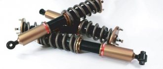
Multidirectional loads act on the axle shaft while the vehicle is moving:
The greater the weight of the car, the stronger these loads. As a result, three main types of axle shafts have been designed: semi-balanced, ¾-balanced and fully balanced. The difference between them is in the method of attaching the axle shaft to the wheel hub.
Types of axle shafts: A. Semi-loaded. B. 3/4 unloaded. B. Completely unloaded.
Semi-loaded - the simplest in design, but at the same time subject to all bending forces. They are installed mainly on passenger cars where no special load capacity or maneuverability is required. In this case, the wheel hub is fixed to the axle shaft (via a spline or flange connection), and the shaft itself rests on a bearing.
Fully unloaded - axle shafts that, thanks to a special fastening method, are freed from lateral and longitudinal loads and transmit only torque. In this case, the axle shaft is fixed to the hub, and the hub rests on two bearings, widely spaced from each other. Installed on heavy trucks and other commercial vehicles.
As a rule, the left and right axle shafts are not identical: they differ in length, and most often the right one is longer than the left one, vice versa. The reason is the asymmetrical arrangement of the differential on the axle (inter-axle on front- or rear-wheel drive vehicles and inter-axle on all-wheel drive).
The method of attachment to the hub and differential depends on the design: it is either a spline connection or a flange connection.
Since the axle shaft is a prefabricated element, it is quite difficult to talk about the material of manufacture: one metal is used for CV joints, and another for the shaft. As a rule, shafts are made of medium carbon steel with the addition of chromium, nickel and molybdenum.
The drive shaft axis can be solid, monobloc or assembled with a ball bushing.
Solid - a solid metal shaft, most often used on the front axle. The simplest and most reliable design.
Monoblock is also a solid shaft, but hollow inside. It is used where it is necessary to lighten the suspension as much as possible.
A shaft with a ball bushing is used primarily for SUVs: this design allows for an additional degree of freedom for turns and maneuvers in difficult areas. The linear bushing provides additional axial compression and extension of the shaft, as well as maximum comfort and silent operation.
Axle shaft with ball bushing
Assembly specifications
During assembly, special attention is paid to the bevel gears of the hypoid transmission. The quality of their engagement is determined by the size of the lateral gap between the teeth, the noise level, and the size and location of the contact patch. Poor build quality significantly reduces the performance of this transmission due to the appearance of scuffing and increases noise. The amount of lateral clearance of the hypoid pair should be in the range of 0.12-0.3-5 mm. The gap between the teeth is measured with a feeler gauge at the wide part of the tooth for at least three teeth of the driven gear.
To ensure adequate installation of the teeth on the contact patch, fix the glass assembly with the drive bevel gear on the gearbox housing and apply a thin layer of oil paint to the working surfaces of the teeth of the driven bevel gear.
After this, slowing down the driven gear, turn the shaft of the drive bevel gear in different directions. If the contact patch position is incorrect, the engagement should be adjusted by moving the drive and driven gears axially, using appropriate shim sets. The movement of the drive bevel gear is realized by changing the thickness of the gaskets installed between the flanges of the drive gear shaft housing and the gearbox housing. The driven gear moves by moving the gaskets from under the flanges of one gear housing cover under the flange of the other cover without changing their overall thickness, so as not to disrupt the adjustment of the drive spur gear shaft bearings.
The noise level (for cars no more than 50, and for trucks no more than 80 dB) must be within acceptable limits. To create preload on the bevel gear shaft bevel bearings, a set of shims are installed between the ends of the bearing inner race and the spacer. In this case, the moment of resistance to rotation of the drive gear shaft in bearings for a Nissan Atlas car should be located in the range of 1.0–3.5 Nm, which corresponds to a force of 16.6–58.3 N.
During differential assembly, the runout of the rear part of the driven bevel gear is monitored, the gearboxes are oriented relative to each other, the lateral clearance in the meshing of the teeth of the axle and satellite gears, and the smooth rotation of the axle gears.
Cardan transmission assembly. The process of assembling the cardan transmission is carried out from pre-assembled components (cardan shafts, intermediate joint support). Before starting assembly, the parts of the cardan transmission must be washed and blown with compressed air, and the needle bearings should be lubricated with liquid lubricant.
Safety valves must be screwed into the openings of the lubrication passages, and the lubrication passages of the crosses must be cleaned. It is necessary to ensure that when assembling the cardan transmission of the ZIL-130 vehicle, the fork flanges at the gearbox and rear axle are located in mutually perpendicular planes.
When assembling cardan gears, control:
· axial play of the crosspieces, ease of rotation of the support bearing,
· moving the sliding fork,
· total circumferential play of cardan shafts,
· check the deflection of the shaft pipe.
The assembled cardan shafts must be balanced. It is recommended, if you have the necessary equipment, to balance the vehicle's driveline assembly. In this case, the cardan transmission is balanced on the side of the front and rear hinges, as well as on the side of the intermediate support.
Steering assembly. This process includes the assembly of the following components:
Causes of failure
Most often, hinges break in axle shafts: CV joints fail due to damage to the boots and the ingress of water and dirt. However, the CV joint can be replaced without changing the entire axle shaft.
It is much more unpleasant when the shaft itself breaks. There may be several reasons: corrosion (on some models rubber balancers are installed, under which the metal deteriorates even faster than in open areas), overloads when driving off-road, sudden loads (falling into a hole, hitting an obstacle). The axle shaft is a reliable design, but there is a certain load limit for which it is designed, and it is better not to exceed this limit.
And finally, axle shafts fail simply from time to time: even the best metal gradually loses its properties, rusts, and the splines wear out. In order not to get stuck somewhere on the road at one “wonderful” moment, at each maintenance a visual diagnosis of the condition of the CV joints and other suspension parts is carried out. First of all, for pockets of corrosion, play, bearing performance, and leaks from under the boots.
Axle shafts are not repaired: the faulty part (usually hinges, less often the shaft itself) is simply replaced with a new one.
For information on how to choose an axle shaft, read our Buyer's Guide.
Source
Main types of axle shafts
Depending on the design, the axle shaft can be fully or partially unloaded from the bending moments acting on it.
Balanced axle shaft
more typical for heavy-duty vehicles, including buses. In the drawing, such an axle shaft will look like a part freely installed inside the bridge, and the wheel hub will rest on the bridge beam using two bearings. In this design, the axle shaft transmits exclusively torque, since the entire bending force is absorbed by the bearings.
Half-loaded axle shaft
in the vast majority of cases it is installed on passenger cars and light trucks. The design of this type of axle shaft is different in that it has a bearing between the axle shaft itself and its casing, and the axle shaft is attached directly to the wheel hub. For this reason, bending moments periodically occur on the arm, which affect the axle shafts in the vertical and horizontal planes.
On front-wheel drive vehicles, axle shafts of a slightly different design are installed to transmit torque from the gearbox to the wheels. Such a drive shaft consists of an axle, internal and external CV joints.
Drive shaft design of a front-wheel drive vehicle.
Purpose and types of axle shafts | Transmission
The torque from the differential side gears to the drive wheels is transmitted by shafts called axle shafts. In addition to torque, axle shafts can be loaded with bending moments from forces acting on the drive wheel. Such forces are the reaction of the road F from the vertical load falling on wheel 1 (Fig.
a), traction force P (or braking force during braking), lateral force T, which occurs when turning and skidding. Depending on the installation method, the axle shafts can be completely or partially unloaded from bending moments arising under the action of the listed forces at distances c and z, respectively.
The fully unloaded axle shaft 4 (Fig. b) is installed with its inner end on splines in the differential side gear, the housing of which rests on bearings, and is connected to the wheel hub with the outer end using a flange. The hub 5 with the wheel is mounted on two bearings 2 on the bridge beam 3.
With this installation, the axle shaft transmits only torque, and all bending moments are absorbed through the bearings by the bridge beam, which facilitates the operating conditions of the axle shaft. Fully balanced axle shafts are used on transport wheeled vehicles of medium and heavy load capacity.
Rice. Axle shaft installation diagram
In the drive of the steered drive wheels to the constant velocity joint 19, torque is supplied from the differential by the inner axle shaft 6. The outer axle shaft 23 has a flange, from which the torque is transmitted to the wheel hub 2. The wheel hub is mounted on a steering axle 22 using two tapered roller bearings 1, which transmit all bending moments from the above forces to the axle.
If the axle shaft with its outer end directly rests on bearings 2 (see a) installed in the bridge beam, then it receives bending moments from all the forces listed above and, in addition, transmits torque to the drive wheel. Axle shafts of this type are called semi-balanced.
DETAILS: Lada Granta and Kalina - replacing rear wheel brake pads - Za Rulem magazine
On high-speed tracked vehicles, the turning mechanisms used to control movement are included in the transmission, since torque is transmitted through them from the engine to the drive wheels.
ustroistvo-avtomobilya.ru
Causes of axle shaft failure
During the operation of the vehicle, the axle shaft constantly operates under quite serious loads, including:
Axle shafts experience almost extreme loads when the vehicle moves on dirt roads, as well as on broken highways.
During operation of the drive axle, it is necessary to periodically check the condition of the bearings located on the axle shafts. Their long-lasting performance can be achieved by providing complete protection against the penetration of dirt and liquids.
Safety first
The differential is designed to ensure safe, comfortable maneuvering on the highway. The disadvantages described above apply to driving in extreme conditions, as well as on rough terrain. Therefore, if your vehicle is equipped with a manual locking drive, it should only be used in appropriate road conditions. And highway cars, which are difficult to “persuad” to drive slower than 100 km/h, are generally impossible and even dangerous to operate without a differential. This is a simple, but infinitely important mechanism in the transmission.
Axle shaft failures
It should be noted that the axle shaft in most car models is considered a very reliable part that rarely fails. This is especially true for cars operating in the urban cycle. But still there are problems with them.
Quite often, the cause of early failure of axle shaft bearings is transmission oil leakage due to wear of the axle shaft seal. When the machine moves, the oil heats up, washing away the lubricant of the bearings, which increases the force of internal friction and destroys them.
In general, bearings are the most common cause of axle shaft failure. In addition to being filled with transmission oil, they break due to defects in the locking rings, and sometimes become jammed due to foreign objects.
A torn CV joint boot leads to failure of both the angular velocity joint and the drive shaft as a whole.
Due to prolonged use, the axle shaft can become loose at the mounting points, even leading to the splines breaking. It is extremely rare, but breakdowns of the axle shafts themselves with separation into two parts also occur. Most often they break in the middle, at the spline or near the bearing.
On cars with front-wheel drive, CV joint boots often tear, which subsequently has a detrimental effect on the joints.
Problems can be caused by accident, prolonged or excessively careless operation of the car, unprofessional repair work, or poor quality of the parts themselves. Repair is most often carried out by replacing the axle shaft, bearings or other elements of the mechanism.
Source
Recommendations for replacing internal CV joints
The automatic transmission system also contains a number of bearings, which can cause the entire gearbox to fail. For example, such vital elements for a car include the outboard intermediate bearing of the drive shaft. Of course, if one bearing breaks, it won’t lead to anything serious, but still, driving with a strong roar from under the hood is not very pleasant.
DETAILS: Four effective methods for cleaning injectors in garage conditions
Another detail that is worth paying attention to is the hinge kit; the drive shaft cannot do without this structural element. It is this that ensures the uniform transmission of traction forces that fall on the drive wheels.
Most often, drive shaft joints fail due to a leaky boot. The malfunction of this part is immediately visible; you will feel how unevenly the weight of the car is distributed on the wheels while driving. Of course, first of all you need to check the tire pressure, and then deal with the automatic transmission.
The constant velocity joint is a bowl-shaped housing with an axle shaft (trunnion), into which a cage and a cage with bearings are inserted. Special grooves are applied on the outer surface of the holder and the inner side of the body. When in motion, the inner race transmits force to the CV joint housing, causing it to rotate.
The dimensions of the parts are different: the internal CV joints are made more massive compared to the external ones.
There are two types of hinges: regular (with ball bearings that move along the dividing grooves) and tripoidal, in which three rollers with hemispherical surfaces rotate on needle bearings. According to their design, hinges can be dismountable or non-dismountable.
For the manufacture of CV joints, high-strength alloys are used, which theoretically guarantee a long service life of the unit and the absence of malfunctions.
As a rule, to replace a part it is necessary to remove the front wheel, unscrew the fasteners of the suspension elements and remove the corresponding drive shaft assembly with constant velocity joints. Also, this operation requires first draining the transmission oil from the gearbox to at least 1/3 of its total volume.
Next, the protective boots and the CV joints themselves are removed from the dismantled axle shaft.
In some cases, it is necessary to knock the hinges off the shaft with a hammer, and sometimes to remove parts of a collapsed CV joint from the axle shaft, it is necessary to use a milling cutter or grinder.
For owners of cars on which CV joints of a collapsible design are installed, there is an alternative, faster option: It is necessary to open the clamps and move the boot of the inner CV joint onto the axle shaft. The bolts on the inner hinge are then screwed together, resulting in the structure being held in place by the flange fit.
By turning the front wheels to their extreme positions, you can achieve a situation in which the drive falls out of the gearbox on its own. After this, all that remains is to replace the inner CV joint, add lubricant, install a new boot and assemble the structure.
Knowing the characteristic symptoms of failure of internal CV joints and understanding the potential causes of this malfunction will allow you to detect the breakdown in time and take measures to ensure safe operation of the vehicle.
The principle of operation of axle shafts on a car
Although the drive shaft, often referred to as the axle shaft, is not part of the driveline, it is part of the vehicle's transmission and is an important part of it.
Today we will look at what tasks the PV performs, what axle shafts are, and how they function.
Let's also consider why these transmission components fail and how to increase their service life.
Purpose of the axle shaft
All drivers know what a car axle shaft is. The main function of this part is to transmit torque to the drive wheels, support the ability to turn the wheels at speed, and also ensure smooth movement of the vehicle in the presence of minor vibrations.
As a rule, the drive shaft is installed on non-steering wheels on vehicles with dependent suspension. In the case of an independent suspension, this function is taken over by the cardan transmission, and on the unsteered (for passenger cars these are the rear) wheels, a hinge mechanism of unequal angular velocities is installed, and on the steered front wheels, a constant velocity joint copes with this task.
In general terms, we can describe what axle shafts are intended for, as the ability to perceive the action of various forces generated as a result of the movement of the car. Note that in absolute terms these are very serious loads, so increased demands are placed on the design of the axle shafts and the material used to make them.
The presence of two hinges in the drive shaft, located at both ends of the part, can significantly reduce vibrations transmitted to the steering column, preventing jerky movement of the machine.
Remedy
Increased noise from the rear wheels
— The wheel fastening is loose
Tighten the wheel nuts
— Wear or destruction of the axle ball bearing
Inspect the axle shaft and replace the bearing
Constant increased noise when the rear axle is operating
— The rear axle beam is deformed, the axle bearings are damaged
Straighten the beam and check its dimensions, replace the axle bearings
— The axle shafts are deformed and have unacceptable runout
Replace the axle shafts with new ones
— Incorrect adjustment, damage or wear of gears or gear bearings
Determine the gearbox malfunction, repair or replace the gearbox
— Worn or incorrectly adjusted differential bearings
Remove the gearbox, repair and adjust
Noise when accelerating and braking the car
— Incorrect adjustment of the main gear gear engagement
— Damage to the axle bearings
— Insufficient amount of oil
Restore the oil level and check for leaks in the seals or rear axle beam
— Incorrect side clearance in the meshing of the final drive gears
— Increased clearance in the drive gear bearings due to loosening of the flange nut or wear of the bearings
Adjust the clearance, replace bearings if necessary
Noise when cornering
— Damage to axle bearings
Knock when starting to move the car
— Wear of the hole for the pinion axle in the differential box
Replace the differential box and, if necessary, the pinion axle
— The rear suspension rod mounting bolts are loose
Oil leak
— Worn or damaged drive gear oil seal
— Wear of the axle shaft seal, leading to oiling of the brake shields, drums and pads
Check the runout of the axle shaft and beam deflection. Repair or replace damaged parts
— Loosening of the bolts securing the rear axle gear housing, damage to the sealing gaskets
Tighten the bolts, replace the gaskets
Design, operating principle of PV
The design of the axle shaft is designed in such a way that maximum torque transmission is ensured regardless of the current position of the wheels. Let's look at what the axle shaft consists of:
Physically, the axle shaft is a section of a solid pipe, to the ends of which adapters for mounting angular velocity joints are attached by welding. To prevent these parts from turning, they are splined.
The shaft is additionally fixed at the junction with the adapter with a locking ring, which prevents the possibility of the axle detaching from the CV joint.
This is the double-joint design used on most front-wheel drive vehicles, with both joints performing slightly different tasks. The internal ones dampen vibrations during vertical movements of the wheels (hitting over uneven road surfaces), the external hinges are responsible for the movement of the wheel rims when the direction of movement of the vehicle changes, that is, when turning.
The wheel hub is attached to the PV using a flange - this method is considered the most reliable and therefore has become widespread. From the inside, fastening to the semi-axial gear is carried out using splines. There are also flangeless PVs, which also have splines on the outer side of the shaft onto which the hub or wheel flange is attached (this design is used, in particular, in KrAZ/MAZ trucks).
The wheel disk is attached to the shaft flange with nuts, and a ball bearing is pressed onto the end of the axle shaft. Rubber seals prevent grease from leaking out of the internal cavity of the bearing. The drive shaft itself is mounted on a bearing using a steel tip with a special groove. The tip itself is tightly welded to the PV casing. The bearing is secured with a retaining ring, which is pressed onto the shaft. Between the clamping ring and the ball bearing there is a spring ring, the purpose of which is to increase the reliability of the bearing fixation.
The bearing is secured in the recess by means of a plate mounted on the flange using a bolted connection. The brake shield is also attached here, as well as the oil deflector. To prevent the bearing from knocking, a spring spacer is installed under the outer ring.
We figured out what a car axle shaft is, only in general terms, since the specific implementation depends on the type of drive shaft.
The design and principle of operation of the axle shaft in a car
The design of the axle shaft is such that the effect of power transmission will be maximum at any position of the wheels. This design consists of three parts: an external constant velocity joint (CV joint); shaft; internal CV joint. A shaft is, roughly speaking, a piece of pipe of a certain length to which adapters for installing CV joints are welded. To prevent these elements from scrolling, they are equipped with special slots.
At the end of the adapter, the shaft is secured with a retaining ring, otherwise the shaft may jump out of the CV joint when moving. In passenger cars, the front drive wheel is driven by external and internal constant velocity joints connected by an axle shaft. The use of two hinges in the drive is caused by the independent suspension of the front wheels. The internal hinges are responsible for the movement of the wheels during vertical suspension strokes, and the external hinges are responsible for turning the wheels relative to the vertical axis, which is necessary when changing
Classification of axle shafts
Since the drive shaft consists of many elements, they are all made from different materials. The axle shaft itself is made from special grades of steel with additives that ensure the highest strength of the product for all possible loads.
Depending on the manufacturing method, the following types of axle shafts are distinguished:
Let's consider what forces act on the drive shaft when the car moves. This, of course, is the force of gravity, which is activated during the vertical component, as well as lateral and tangential loads that occur when the car turns, during skids, when driving along a section of the road with a transverse slope, as a result of the influence of lateral air flow (gusts of wind) .
Depending on the design of the external fastening, which determines the level of loading of the shaft by bending moments of different directions, the following types of axle shafts are distinguished:
In the latter case, the shaft design provides for only a support bearing to which the wheel disk/hub is attached. Since this design is not able to absorb bending loads, it is used relatively rarely.
A semi-loaded drive shaft is usually installed on passenger cars, as well as light-duty trucks that do not experience significant vertical loads.
In this case, the installation location of the bearing is between the primary housing and the axle shaft itself, which, in turn, is attached to the wheel hub. This design leads to the appearance of multidirectional bending moments acting on the PV in the horizontal/vertical planes, as well as in the plane of rotation of the wheel on the shoulder, the length of which is equal to the diameter of the tire.
A fully balanced drive shaft is the prerogative of buses and heavy trucks. Inside the bridge, such a structure is installed freely; fixation on the bridge beam is carried out by means of two bearings, which are responsible for damping all types of bending moments. The axle shaft turns out to be free and is responsible only for transmitting torque from the power unit to the wheels.
The disadvantages are the exact opposite of the advantages of semi-balanced axle shafts:
A semi-minor axis is... What is a semi-minor axis?
Not to be confused with the term "Ellipsis".
Ellipse and its focuses
Ellipse (ancient Greek ἔλλειψις - disadvantage, in the sense of lack of eccentricity up to 1) - the geometric locus of points M of the Euclidean plane for which the sum of the distances from two given points F1 and F2 (called foci) is constant, that is
| F1M | | F2M | = 2a.
A circle is a special case of an ellipse. Along with a hyperbola and a parabola, an ellipse is a conic section and a quadric. An ellipse can also be described as the intersection of a plane and a circular cylinder, or as the orthogonal projection of a circle onto a plane.
Related definitions
- The segment AB passing through the foci of the ellipse, the ends of which lie on the ellipse, is called the major axis of this ellipse. The length of the major axis is 2a in the above equation.
- The segment CD perpendicular to the major axis of the ellipse, passing through the central point of the major axis, the ends of which lie on the ellipse, is called the minor axis of the ellipse.
- The intersection point of the major and minor axes of an ellipse is called its center.
- The intersection point of an ellipse with its axes is called its vertices.
- The segments drawn from the center of the ellipse to the vertices on the major and minor axes are called, respectively, the semi-major axis and semi-minor axis of the ellipse, and are designated a and b.
- The distances r1 and r2 from each focus to a given point on the ellipse are called the focal radii at that point.
- The distance is called the focal distance.
- The eccentricity of an ellipse is called the ratio. Eccentricity (also denoted ε) characterizes the elongation of the ellipse as it changes. The closer the eccentricity is to zero, the more the ellipse resembles a circle, and vice versa, the closer the eccentricity is to unity, the more elongated it is.
- The focal parameter is half the length of the chord passing through the focus and perpendicular to the major axis of the ellipse.
- The ratio of the lengths of the minor and major semi-axes is called the ellipse compression ratio or ellipticity: . A value equal to is called compression of the ellipse. For a circle, the compression coefficient is equal to one, the compression is zero. The coefficient and eccentricity of the ellipse are related by the relation
Properties
- Focal property. If F1 and F2 are the foci of the ellipse, then for any point X belonging to the ellipse, the angle between the tangent at this point and the line (F1X) is equal to the angle between this tangent and the line (F2X).
- A straight line drawn through the midpoints of segments cut off by two parallel lines intersecting an ellipse will always pass through the center of the ellipse. This allows you to easily obtain the center of the ellipse, and subsequently the axes, vertices and foci, by constructing using a compass and ruler.
- The evolute of the ellipse is the astroid.
An ellipse can also be described as
Relationships between ellipse elements
Parts of an ellipse (see Related Definitions for description)