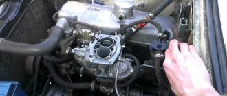
ECONOSTAT
Repair and cleaning of the VAZ 2109 carburetor
The econostat enriches the combustible mixture prepared by the second chamber at maximum throttle opening. It is made in the form of a separate sprayer, which is an inclined tube located in the upper part of the second mixing chamber. The outlet of the atomizer is located near the center of the chamber above the hole of the small diffuser. Fuel is supplied to the econostat sprayer directly from the float chamber through a tube, at the lower end of which there is a fuel nozzle. The tube is installed vertically in the carburetor cover and reaches almost to the bottom of the float chamber. The econostat channels are entirely located in the carburetor cover. Since the econostat atomizer is located in a low vacuum zone, the flow of fuel from it and, accordingly, the necessary enrichment of the combustible mixture begins only at a high crankshaft speed and with the throttle valves fully open, when the vacuum above the diffuser of the second chamber becomes sufficient to extract fuel from the float chamber.
ACCELERATING PUMP
Diaphragm type accelerator pump with two nozzles directed into both mixing chambers. The accelerator pump housing is combined with the carburetor body and is closed by a cover with a hole for a telescopic spring-loaded diaphragm pusher. The accelerator pump is driven by a cam mounted on the throttle valve axis of the first chamber. When you press the gas pedal, the cam, rotating together with the throttle valve axis, acts on the profiled end of the pump drive lever. The other end of the lever presses the diaphragm pusher. The pump sprayer is made in the form of two thin tubes with calibration holes at the ends, connected together by a common body. It is installed at the end of the vertical channel of the carburetor body. The connection is sealed with a rubber ring placed on the spray body. The nozzle is kept from moving by the carburetor cover. A ball discharge valve is installed in the spray body. The check (suction) valve is pressed into the lower part of the vertical channel. Fuel enters this channel through a hole in the side wall of the float chamber. The ends of the accelerator pump nozzle tubes are directed into the spaces between the walls of the small and large diffusers of both chambers. In this case, the outlet openings of the atomizer tubes are oriented so that the fuel stream from them does not fall on the walls of the mixing chambers, small diffusers and throttle valve axles, that is, the fuel is injected directly into the intake pipe. The performance of the accelerator pump is determined by the cam profile of its drive. The cam has markings stamped on its surface. The characteristics of the accelerator pump also depend on the diaphragm pusher spring and the flow sections of the spray tubes. The stiffness of the spring determines the fuel pressure in the nozzle, and the diameter of the outlet holes of the nozzle determines the duration of injection. The sprayer is also marked.
A distinctive feature of the accelerator pump of the Solex family of carburetors is the absence of a drain jet or other devices that reduce the amount of fuel injected when the throttle valve is slowly opened. All gasoline displaced by the diaphragm from the cavity of the accelerator pump enters through the atomizer into the mixing chambers. Therefore, there is another feature of Solex carburetors in the basic version, which is directly related to the operation of the accelerator pump. When accelerating a car with partial pressing of the gas pedal, the flap of the second chamber is not yet open, and gasoline is injected into this chamber. To prevent it from accumulating there, there must be a gap between the chamber wall and the closed throttle valve, visible to the light.
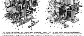
Acceleration pump: 1 - outlet of the sprayer in the second chamber; 2 - outlet of the sprayer in the first chamber; 3 - sprayer; 4 — discharge valve ball; 5 - diaphragm; 6 — diaphragm return spring; 7 — pusher spring; 8 — pusher; 9 — lever; 10 — lever axis; 11 - cam; 12 — axis of the throttle valve of the first chamber; 13 — suction valve ball; 14 — channel for supplying fuel from the float chamber.
Main types of jets and their selection
The industry produces 2 types of carburetor jets, which are included in each repair kit:
They are made for each camera of the device. The choice of jet depends on the cross-section of the large and small carburetor diffuser. Repair kits are produced differently - for each model and brand of car. The parts differ in hole diameter. How to adjust the correct operation of the engine - information necessary for every vehicle owner.
https://youtube.com/watch?v=9YsPr_IfCdo
Quite often, the Solex carburetor is installed on cars of other brands, with the most powerful engines. In this case, the machine will work intermittently, because the VAZ jets will not be able to do their job efficiently - due to the diameter being insufficient to supply the enriched mixture.
Often, car enthusiasts install a large fuel part for better acceleration and dynamic driving. In this case, one should not forget about the increase in fuel consumption. Also, increasing the diameter of the nozzle by several orders of magnitude will not always give a good result. The table can tell you how to choose jets.
If the engine capacity is 1.6 liters, you should not install a main jet from a powerful engine on it. If you are no longer satisfied with the acceleration of your car, you may need to look for another reason, for example:
- low compression level in one of the cylinders;
- the adjustment of the ignition system has gone wrong;
- one or more spark plugs are faulty;
- Replacement of high-voltage wires is required.
These are just some of the reasons and malfunctions, by eliminating which you will get a fast car again. Car enthusiasts have different opinions about altering jets, but most believe that it is not worth doing. Sometimes, those who like to save money install jets whose sizes are smaller than the recommended ones. In this case, you get an economical, but very weak car that will take a very long time to accelerate. Ozone carburetor jets should not be installed in a Ford carburetor. They should be on the classic Zhiguli.
The principle of operation of the carburetor accelerator pump
Repair of oil pump VAZ 2108
The diaphragm (membrane) is connected to the fist through a lever that is located on the throttle valve. When the valve is closed, fuel flows freely into the cavity, the suction valve opens it up. When the damper is open, the valve, on the contrary, prevents fuel from flowing out of the cavity. Air does not enter this cavity under any circumstances. Gasoline is also supplied to the sprayers through this valve. Suction occurs under the action of the spring, and discharge occurs due to the mechanical action of the lever on the diaphragm head. The accelerator pump nozzles are responsible for supplying fuel to the nozzles. One accelerator pump nozzle is routed to each carburetor chamber. The jets are installed on the same platform as the discharge valve. To gain access to the jets, you need to gain access to the carburetor chambers.
Method of folk Kulibins
Cooling system liquid pump repair
Vacuum carburetors often fail for this reason. To the question: what to do, people have long found an answer. In general, there are three solutions:
- The easiest, but also the most expensive, is to just buy a new carburetor and throw the old one in a box with garage trash, and go for a ride and enjoy the speed;
- Order and wait a long time for a part;
- Take special glue and simply seal holes or cracks in the membrane.
The third method is, of course, temporary, but with high-quality work and good materials, your membrane will last longer than the new ones from the repair kit. For gluing, we prepare a convenient place, glue, scissors and material for the patch.
We take the material for the patch. The Internet is replete with names of exotic materials. There are condoms, balloons, and surgical gloves. However, it is better to use an elastic, thinner membrane from another device. This patch will be more reliable. We cut it with scissors to the size of our part, coat it with glue.
What glue is best to use? People advise using any cyanoacrylic-based glue for gluing rubber products. We apply it to the damaged part and our patch, connect them, press and hold for a while. We leave our gluing until the glue is completely dry, assemble and install the carburetor on the scooter engine and ride with pleasure.
In conclusion, we note that all troubles with any mechanism can be solved on your own, saving time and money from the family budget.
Carburetor accelerator pump
05.02.2011
All the systems described above ensure engine operation in stationary conditions, when operating modes do not change or change smoothly. When you press the gas pedal sharply, the fuel supply conditions are completely different. The fact is that the fuel enters the engine cylinders only partially evaporated. Some of it moves along the intake pipe in the form of a liquid film, evaporating from the heat supplied to the intake pipe from the coolant circulating in a special jacket at the bottom of the intake pipe. The film moves slowly and final evaporation can occur already in the engine cylinders. With a sharp change in the throttle position, the air almost instantly takes on a new state and reaches the cylinders, which cannot be said about the fuel. The part of it that is enclosed in the film cannot quickly reach the cylinders, which causes some delay - a “failure” when the throttles are opened sharply. It is aggravated by the fact that when the throttles are opened, the vacuum in the intake pipe drops, and at the same time the conditions for evaporation of gasoline worsen.
To eliminate the unpleasant “failure” during acceleration, so-called accelerator pumps are installed on carburetors - devices that supply additional fuel only during sudden throttle openings. Of course, it will also largely turn into a fuel film, but with more gasoline, the “failure” can be smoothed out.
Fig. 12. Diagram of the economizer and accelerator pump: 1 - drive strip; 2 — accelerator pump piston; 3 - drive lever with roller; 4 - traction; 5 — accelerator pump nozzle; 6 — economizer sprayer; 7 - discharge valve; 8 — accelerator pump fuel supply channel; 9 — economizer fuel supply dripping; 10 — throttle lever; 11 — inlet valve; 12 — economizer valve; 13 — economizer pressure rod; 14 - guide rod
K-126 carburetors use a mechanical piston-type accelerator pump, which supplies fuel to both chambers of the carburetor regardless of air flow (Fig. 12). It has a piston 2 moving in the discharge chamber, and two valves - inlet 11 and discharge 7, located in front of the nozzle block. The piston is fixed to a common bar 1 together with the economizer pressure rod. The piston moves upward during the suction stroke (when the throttle is closed) under the action of a return spring, and when the throttle is opened, the bar with the piston moves down under the action of lever 3, driven by rod 4 from throttle lever 10. In the first designs of the K-126, the piston did not have a special seal and had inevitable leaks during operation. The modern piston has a rubber sealing collar that completely isolates the discharge cavity.
During the suction stroke, under the action of the spring, piston 2 rises and increases the volume of the discharge cavity. Gasoline from the float chamber through the inlet valve 11 freely passes into the discharge chamber. The discharge valve 7 in front of the sprayer closes and does not let air into the discharge chamber.
When the throttle drive lever 10 is sharply turned, rod 4 turns lever 3 with a roller on the axis, which presses bar 1 with piston 2. Since the piston is connected to the bar through a spring, in the first moments there is no movement of the diaphragm, but only compression of the spring under the bar, since gasoline filling the chamber cannot leave it quickly. Next, the already compressed piston spring begins to squeeze gasoline out of the discharge chamber to the atomizer 5. The discharge valve does not prevent this, and the inlet valve 11 blocks possible fuel leakage back into the float chamber.
The injection is thus determined by the piston spring, which must, at a minimum, overcome the friction of the piston and its cuff against the walls of the discharge chamber. Subtracting this force, the spring determines the injection pressure and implements continued fuel injection for 12 seconds. The injection ends when the piston lowers to the bottom of the injection chamber. Further movement of the bar only compresses the spring.
Category: Carburetor K-126, K-135
Previously Carburetor K-126, K-135. Economizer
Later Carburetor K-126 starting device
Adjustment of speed XX Ozone 2105, 2107
Adjusting the idle speed of carburetors 2105, 2107 Ozone and their modifications is one of the most frequently performed operations in carburetor maintenance. As a result, it is necessary to achieve stable engine operation at a crankshaft speed of 850-900 rpm, as well as to normalize the content of CO and CH in the exhaust gases.
If the idle speed is adjusted incorrectly, the engine may start and immediately stall, it may stall, during acceleration there may be a “failure”, and during operation there will be increased fuel consumption.
Tools required for adjusting XX speed
— tachometer (you can use the one built into the instrument panel) — slotted screwdriver (3 mm) If you don’t have a tachometer, you can adjust the idle speed by ear. But for this you must have at least some experience in car repair, since it is necessary to distinguish when the speed is normal and when it is increased or decreased.
Preparatory work
Before making adjustments, you must first make sure that the ignition timing is set correctly. The distributor cover, breaker contacts, armored wire and spark plugs are in good condition.
If the carburetor is after disassembly and reassembly or you simply need to set the initial value of the adjustment screws, then first tighten them completely, and then turn out the “quality” screw by 2-3 turns, and the “quantity” screw by 3-4.
— Warm up the engine to operating temperature (85-95). — With the engine stopped, connect the tachometer and start it again.
procedure for connecting an autotester (tachometer)
Adjusting the idle speed of an engine with a carburetor 2105, 2107 Ozone We carry out the adjustment in four steps.
1. Turn the “quality” screw and set the maximum idle speed.
Rotate the screw counterclockwise.
turn the “quality” screw of the fuel mixture of the carburetor 2105, 2107 Ozone counterclockwise, thereby increasing the supply of gasoline to the fuel-air mixture
2. Using the “quantity” screw, we set the rotation speed to an even higher speed. For example, 80 rpm more. Rotate the screw counterclockwise.
rotate the “amount” screw of the fuel mixture counterclockwise, increasing the total amount of fuel mixture entering the engine cylinders
3. We check with the “quality” screw whether these revolutions are the maximum for the given position of the “quantity” screw.
Simply rotating it back and forth.
We check by rotating the “quality” screw in different directions whether the set idle speed is maximum
If not, then we carry out the above adjustments again.
4. Keeping the position of the “quantity” screw of the fuel mixture unchanged, tighten the “quality” screw so much that the speed drops to 850-900 rpm.
Adjustment in this way is very simple, but at the same time convenient, since it does not require special equipment. Notes and additions If, after such adjustment, the content of CO and CH emissions does not correspond to the norm or the idle speed cannot be adjusted, then it is necessary to check:
— whether the fuel and air jets of the main dosing system are dirty; — whether the main fuel jets of the first and second chambers are reversed; — whether the fuel level in the float chamber is increased; — Is the needle valve working? - Is the fuel jet of the idle system clogged; — whether the holder of the fuel jet of the idle system or the solenoid valve has turned away; — whether the tubes have come off the electro-pneumatic valve; — whether the rubber o-ring on the fuel mixture “quality” screw is damaged.
— In some cases, it makes sense to modify the carburetor idle system. See “Modification of the idle system of Solex and Ozone carburetors.”
Five more articles on the site on adjusting and tuning carburetors 2105, 2107 Ozone
— Adjusting the fuel level in the float chamber of carburetors 2105, 2107 Ozone
— Adjustment of the starting device of carburetors 2105, 2107 Ozone
— Adjusting the air damper drive of carburetors 2105, 2107 Ozone
— Adjusting the throttle valve drive of the first chamber of carburetors 2105, 2107 Ozone
— Pneumatic drive of the throttle valve of the second chamber of carburetors 2105, 2107 Ozone
twokarburators.ru
Acceleration pump
The accelerator pump serves to enrich the mixture when the throttle is opened sharply. A diagram of a mechanically driven accelerator pump, often combined with an economizer drive, is shown in Fig. 104, g. When the throttle is sharply opened, the lever 21 associated with it, through the rod 19 and the bar 18, compresses the spring 25, which moves the piston 27 down. As a result, the pressure in the well 28 increases and the check valve 26 closes, which prevents fuel from flowing into the float chamber. Through the opened discharge valve 24 and pump jet 23, fuel additionally enters the mixing chamber and the mixture is enriched.
The accelerator pump, designed for short-term enrichment of the mixture, has a mechanical drive and an adjustable flow rate. The piston rod 28 is made with grooves. The pump has a needle discharge valve 20 and a ball check valve 21. When the throttle valve is opened sharply, the piston moves quickly under the action of a spring, the discharge valve opens and fuel is injected.
A mechanically driven accelerator pump is connected in parallel with the economizer. The stroke of the pump plunger can be changed by moving the rod into the spare holes.
A mechanically driven accelerator pump is connected in parallel to the main dosing system. The specially designed throttle valve is placed on a needle bearing and is also a pneumatic speed regulator.
The accelerator pump and economizer are separate, but supply fuel through a common channel and power jet.
The accelerator pump consists of a well in which the piston moves and a valve system. The piston is moved by rod 8, which by means of rod 30 (Fig.
The accelerator pump, which is introduced into the carburetor design, allows you to enrich the mixture during the period of sharp opening of the damper and thereby eliminates the disadvantage of a simple carburetor. When the throttle valve is opened sharply, the pump piston connected to its axis quickly lowers and pumps gasoline into the mixing chamber. The mixture becomes richer and the engine quickly increases speed. In this case, gasoline cannot flow into the float chamber, since this is prevented by the check valve. If the throttle valve opens smoothly, the piston moves down slowly, the check valve remains open and gasoline flows freely into the float chamber.
The accelerator pump serves to enrich the mixture when the throttle valve is opened sharply. In this case, lever 18 (Fig. 7.3, d), connected by link 24 to rod 17, acts on bar 16 and moves piston 21 down. The fuel pressure in the pump well increases and the check valve 20 closes, preventing fuel from flowing into the float chamber. Through the opened injection valve 23 and the spray nozzle 22, gasoline is additionally injected into the mixing chamber, and the combustible mixture is briefly enriched.
| Carburetor starter diagram. |
The accelerator pump serves to enrich the mixture when the throttle valve is opened sharply and the load on the engine increases. Acceleration pumps are mechanically or vacuum driven.
| Carburetor diagram K. - 126G. |
The accelerator pump is connected by a system of levers and rods to the throttle valve drive. It has a rod with a cuff made of oil-gasoline-resistant plastic, which performs the functions of a piston.
The accelerator pump in the K-126 N carburetor operates when the throttle valves are sharply opened. In this case, the main part of the fuel under the action of piston 23, opening the discharge valve / /, is injected through the sprayer 14 into the primary chamber. Excess fuel from the pump well is forced out through the bypass hole 28 into the float chamber. The dimensions of hole 28 are selected so that when the throttle valve of the primary chamber is opened by 35, part of the fuel flows into the float chamber and is injected about one third of its volume. When the throttle valves are further opened, the bypass hole is closed by the pump piston and the remaining fuel is injected into the primary chamber.
The accelerator pump serves to enrich the mixture when the throttle valve is opened sharply and the load on the engine increases. Acceleration pumps are mechanically or vacuum driven.
| Scheme of the K-126 G carburetor. |
Tuning the exhaust system of VAZ 2107
Some car owners make the engine sound louder so that it resembles the growl of sports cars. To do this, the catalyst is replaced with a special flame arrester. Other VAZ 2107 owners believe that tuning the exhaust system is justified if the result is an increase in engine power. When assessing the feasibility of such measures, it should be borne in mind that improper installation will lead to increased fuel consumption and deterioration in vehicle performance. Therefore, work on tuning the exhaust system should be entrusted to professionals.
Tuning the exhaust manifold and exhaust pipe
For better purging of exhaust gases, extreme sports enthusiasts replace the standard exhaust manifold with a StinGer spider complete with a double exhaust pipe (pants) made of stainless steel. This allows you to increase power at high speeds by about 9 hp. With. At the same time, the exhaust gas output formula “4–2-1” does not change.
Since the internal walls of the StinGer are smoother, installing such a manifold will increase the efficiency of exhaust gases and increase power at maximum speed by 9 hp. With
The smooth surfaces of the StinGer manifold flanges ensure a tight fit to the cylinder head and to the pants. However, the new exhaust pipe does not have a threaded seat for the oxygen sensor. Therefore, if necessary, a nut is welded on this pipe in front of the catalyst, into which the sensor is installed.
The oxygen sensor in the VAZ 2107 is located on the exhaust pipe in front of the catalyst - this is where the nut for its installation is welded
Since the pants end with a flange, the resonator of the injection model is attached without problems. However, on carburetor VAZ 2107 this unit is designed differently, so it is better to immediately install a resonator from an injection engine on such a car.
Installation of a straight-through muffler
The standard VAZ 2107 muffler consists of two pipes, welded at different angles and lined with a non-flammable mineral wool filler, which reduces the speed of exhaust gases and softens the exhaust. To increase the volume of the exhaust and make the flow of exhaust gases straight, audio tuning of the exhaust system is carried out. Instead of a conventional muffler, a direct-flow muffler made by yourself is installed.
In a direct-flow muffler, the exhaust gases do not make turns, which dampen the speed, and act as additional resistance, reducing engine power
There are two ways to make a direct-flow muffler:
- remake the old muffler, which will not cause problems even for inexperienced owners and will be very cheap;
- weld a new muffler, which will be quite difficult to secure under the bottom of the car.
The work is performed in the following order:
- The old muffler is removed.
- A window is cut out along the entire length of the oval body using a grinder.
- The filler is removed and the metal insides are cut out.
- Using a drill or grinder, perforate a piece of pipe equal to the length of the muffler (52 cm). A large number of holes or slots will disperse the flow of exhaust gases, reducing temperature and noise.
- A perforated pipe is carefully welded inside the body, connecting the inlet and outlet pipes.
- An exhaust pipe is welded to the rear side of the muffler - it can be double and chrome-plated. The part of the pipe that goes inside the muffler is also perforated using a drill.
- The oval body is filled with mineral wool, fiberglass, asbestos or other non-combustible material.
- The window in the housing is welded.
Video: manufacturing and installation of an adjustable exhaust with a damper for a VAZ 2107
Thus, with the help of tuning you can turn a VAZ 2107 into a completely new car. In accordance with the wishes of the car owner, almost any components and parts are modified, including the engine. Elements for tuning are available for sale, and most of the work is quite simple to complete, carefully following the instructions of professionals.
Checking and subsequent repair of the accelerator pump of the DAAZ Ozone carburetor
Before starting the test, manually pump gasoline into the float chamber and remove the carburetor cover.
The check should begin with the pump itself. By pressing the throttle drive lever, watch the stream of fuel from the nozzle. Ideally, it should be smooth and not touch the walls and axis of the damper. The timed injection should last 1-2 seconds. Problems with operation:
- The stream is weak and crooked. This means you need to clean the channels, atomizer, jets and valves;
- The injection lasts more than two seconds. This indicates a clogged bypass valve;
- Fuel got onto the hull. The diaphragm needs to be replaced or the cap needs to be secured.
Checking the DAAZ Ozone carburetor nozzles
To check the atomizer, you need to unscrew it from the housing. After unscrewing, press the damper lever. If a powerful stream flows from the hole, then the problem is in the sprayer or discharge valve. The nozzle of the sprayer can be easily cleaned with a wire, and the valve needs to be washed and blown out. The working sprayer should have a ball that makes a rattling noise when shaken.
Supply channels UN
If gasoline does not spray out of the hole when you press the throttle lever, the supply channels of the accelerator pump may be clogged. To clean them, you need to remove the diaphragm and clean the fuel supply channels with wire. They should be washed with carburetor cleaning fluid and blown out.
How to check the bypass channel together with the UN jet
When you press the throttle lever, you need to monitor the flow of gasoline into the float chamber. If the stream is not visible and the seething is not even noticeable, then the channel needs to be cleaned. At the same time, you need to wash the bypass jet. Everything is washed in the same way as other channels and blown out with compressed air.
Dampers
Primary adjustment comes down to adjusting the cable on the trigger mechanism and adjusting the accelerator pedal traction. It is easy to adjust the thrust - the plastic tip is placed approximately opposite the hinge, twisting it along the thread. To secure, tighten the nut 10 mm.
The choke drive cable is adjusted as follows. The choke lever in the cabin is pushed in all the way, and the air damper must be fully open. The cable is threaded through the eyes, and the end is inserted into the corresponding hole in the clamp. While holding the latch, tighten the bolt with a wrench. When pulling and retracting the choke, you need to make sure that the damper opens and closes completely.
Next, check how the throttle of the second chamber opens. The membrane and rod must be in such a state that their stroke is sufficient to fully open the damper. If the stroke is not enough, then unscrew the nut that is on the rod and adjust the length.
Signs of carburetor failure
Some typical signs of engine malfunction may indicate the need to repair the carburetor membrane and other parts. These include:
Unstable engine operation occurs.
The main reason for this behavior of the engine is the pouring of a low-quality or incorrectly manufactured mixture of gasoline and oil into the gas tank.
There is a strong overconsumption of the gasoline mixture.
This nuisance entails increased carbon monoxide emissions from the engine exhaust. Very often black smoke comes out of the muffler. This symptom indicates that the fuel in the combustion chamber does not burn completely, and the combustible mixture is highly oversaturated. This may indicate a breakdown in the carburetor.
Floating speed and randomly changing tool power.
Such work will require paying attention to the tightness of the adjustment screws. Another reason may be a malfunction of the protection cap.
This may be a malfunction of the carburetor or membrane, but while searching for the causes, pay attention to the piston group of the engine and measure the compression level in the cylinder. Cleaning and adjusting carburetor parts will help for a while, but be prepared for some capital
The engine constantly sneezes and runs jerkily.
This problem usually occurs when the mixture supply channel is clogged, as well as when gasoline filters and air filters fail. In this case, flushing the carburetor with a special liquid or simple and reliable VD-40 and replacing the filters will help. As a rule, in most cases, it is enough to blow the air filter with air.
To eliminate most accelerator pump failures, the following operation may well help:
- Unscrew the screws securing the top cover. As a rule, there are 5 of them on it. Then we disconnect the damper cable to start the engine in cold conditions and twist the sprayer using a screwdriver. We clean it thoroughly using a thin soft wire or a pointed toothpick. We perform this operation several times, alternating it with air blowing. We blow it out using a pump or a car electric compressor;
- Unscrew several screws securing the camera cover and remove it. We very carefully remove the membrane along with the lever. Here you should keep an eye on the spring so that you don’t have to look for it all over the garage later. Before removing the membrane, be sure to place a piece of cloth under the carburetor to prevent gasoline from flooding the engine and exhaust manifold;
- We replace the damaged or lost elasticity membrane with a new part, install an accelerator pump and check for the presence of injection of flammable liquid into the carburetor. If the volume of gasoline is good, you can start the engine and check its operation at idle. The engine is running normally, the repair with replacement of the carburetor membrane can be considered completed.
Replacing the carburetor membrane
When to change, what interior to install
To perform scheduled maintenance operations, there are regulations, as well as manufacturer recommendations. According to them, replacing the cabin filter of the Kia Rio II JB heating and air conditioning system should be done every 15,000 kilometers or once a year.
Considering that the operating conditions of the car in most cases will be far from ideal, experts advise performing this operation approximately twice as often, in spring and autumn.
Characteristic symptoms:
- Windows often fog up;
- the appearance of unpleasant odors in the cabin when the airflow is turned on;
- deterioration of the stove and air conditioner;
They may make you doubt that the filter element is coping with its tasks and an unscheduled replacement will be required. In principle, these symptoms should be relied upon when choosing the correct replacement interval.
Suitable sizes
When choosing a filter element, owners do not always use products recommended by the car manufacturer. Everyone has their own reasons for this, some say that the original is unreasonably expensive. Some people in the region sell only analogues, so there is a need to know the sizes by which you can subsequently make a selection:
- Height: 17 mm
- Width: 200 mm
- Length: 225 mm
As a rule, sometimes analogues for Kia Rio II JB can be a few millimeters larger or smaller than the original, there is nothing wrong with that. And if the difference is measured in centimeters, then of course it’s worth looking for another option.
Selecting an original cabin filter
The manufacturer recommends using exclusively original consumables, which, in general, is not surprising. They themselves are of good quality and are widely available in car dealerships, but their price may seem overpriced to many car owners.
Regardless of the configuration, on all second-generation Kia Rios (including the restyled version), the manufacturer recommends installing a cabin air filter with article number 97133-2E210 (971332E210) or its full analogue 97133-2E200 (971332E200).
It is worth noting that sometimes consumables and other spare parts may be supplied to dealerships under different part numbers. Which can sometimes confuse those who want to purchase an original product.
When choosing between a dust and carbon product, car owners are advised to use a carbon filter element. This filter is more expensive, but it cleans the air much better.
It is easy to distinguish - the paper filter accordion is impregnated with a carbon composition, and therefore has a dark gray color. The filter cleans the air flow from dust, fine dirt, germs, bacteria and enhances the protection of your lungs.
Which analogues to choose
In addition to simple cabin filters, there are also carbon filters that filter the air more effectively, but they are more expensive. The advantage of coal SF is that it does not allow foreign odors coming from the road (street) to penetrate into the car interior.
But this filter element also has a drawback - air does not pass through it well. GodWill and Corteco carbon filters are of fairly high quality and are a good replacement for the original.
However, in some retail outlets the price of the original second-generation Kia Rio cabin filter may be greatly inflated. In this case, it makes sense to purchase a non-original consumable item. In particular, cabin filters are considered quite popular:
Conventional dust cabin filters
- Mann Filter CU2336 – high-tech consumables from a well-known manufacturer
- BIG filter GB-9910 – popular brand, good fine cleaning
- Nevsky filter NF-6164 - Russian manufacturer with an affordable price
Carbon cabin filters
- TSN 9.7.115 – high-quality and thick carbon coating
- BIG filter GB9910/C – activated carbon
- Nevsky filter NF6164C – normal quality, affordable price
It makes sense to take a closer look at the products of other companies - they also specialize in the production of high-quality consumables for passenger cars:
- Corteco
- Filtron
- SCT
- Sakura
- GoodWill
- Fram
- JS Asakashi
- Champion
- Zekkert
- Masuma
- Nipparts
- Purflux
- Knecht Mahle
- RU54
It is quite possible that sellers may recommend replacing the Rio II JB cabin filter with non-original cheap substitutes with a much smaller thickness. They are not worth buying, since their filtering characteristics are unlikely to be at the proper level.
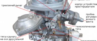
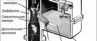
Operating principle
From the gas tank, the fuel mixture through the gas line first enters the cavity in the carburetor, and then goes to the fuel valve seat. When the engine is not running, the inlet hole on the seat is closed by a lever on the axle, which blocks the path into the cavity where the mixture pressure regulator is installed. Gasoline does not enter the combustion chamber.
At the beginning of the carburetor operation and when the unit is started, the rarefaction of the diffuser air through the rod pushes up the membrane in the pressure regulator device. At this time, the lever is pressed back, and the gas mixture passes through the seat into the cavity of the mixture pressure regulator. Then it enters the channels, the passage in which can be changed using adjusting screws, and is supplied to the nozzle device.
Atomized gasoline, enriched with air, is sucked into the diffuser during engine operation and enters the combustion chambers. To prevent air from passing through the cavity, a check valve is installed on the seat. This principle of operation improves the idle performance of the scooter engine.
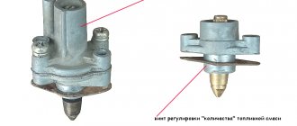
The pressure regulator device consists of a membrane, a lever for closing the fuel channel and a steel spring, which is designed to maintain the same performance indicators of the device. In this case, the carburetor membrane is exposed to rarefied air on one side, and on the other, it is pressed by a spring.
As the air rarefaction increases and atmospheric pressure in the diffuser increases, sufficient force is applied to the membrane to move the lever and open the fuel supply valve. At this moment, the fuel supply increases, which compensates for the drop in pressure level in the cavity of the fuel mixture.
Features and malfunctions of the starting device
With the onset of frost, many owners of “nines” are faced with the problem of poor cold starting of the engine, and the cause of the malfunction is often the starting device (PU), which is designed to enrich the fuel mixture in a certain proportion. When the choke cable is pulled, the air damper closes, but under the influence of vacuum it changes its position, opening slightly and to some extent allowing air to pass into the carburetor. The position of the air intake is also adjusted using a diaphragm device, which is mechanically connected to the damper by a system of rods.