Print this article Font size 16
On a VAZ 2110 car, the brake system has a hydraulic dual-circuit drive. It’s no secret that you can’t go far in a car without brakes and safety in this case is close to zero.
Today we will talk to you about how the brake system works on the domestic VAZ 2110 car, or, more simply, the “ten”, we will analyze its main malfunctions, as well as ways to eliminate potential and existing problems.
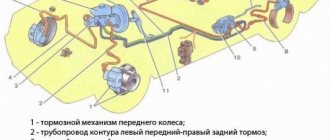
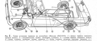
Hydraulic brake circuit diagram
1 – front wheel brake mechanism; 2 – pipeline of the “left front–right rear brake” circuit; 3 – main cylinder for hydraulic brakes; 4 – pipeline of the “right front–left rear brake” circuit; 5 – master cylinder reservoir; 6 – vacuum booster; 7 – rear wheel brake mechanism; 8 – elastic lever of the pressure regulator drive; 9 – pressure regulator; 10 – pressure regulator drive lever; 11 – brake pedal; A – flexible hose of the front brake; B – flexible rear brake hose
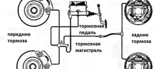
The car uses a working brake system with diagonally separated circuits, which ensures high active safety of the car. One hydraulic drive circuit ensures the operation of the right front and left rear brake mechanisms, the other - the left front and right rear.
If one of the circuits of the service brake system fails, the second circuit is used to stop the vehicle with sufficient efficiency.
The hydraulic drive includes a vacuum booster 6 and a dual-circuit pressure regulator 9 for the rear brakes.
The parking brake system is driven by the brake mechanisms of the rear wheels.
Principle of operation
The “ten” type of braking system, namely a hydraulic dual-circuit with diagonal distribution, works well and can be considered quite reliable. A simple but successful brake system project, which is not always liked by car owners. Although few people take into account the fact that if one circuit decides to stop fulfilling its direct purpose, then the second will give the opportunity to slow down in a timely manner. Both circuits can fail only if there is a global oversight of the technical condition of the “chervonets”.
Reference. The design of the circuit system looks like this: from front left to rear right and vice versa. A kind of “X” of the brake system from the manufacturer.
This type of brake arrangement helps prevent you from going into a strong roll, skidding, turning 360 degrees around one side, or even turning over when braking with one of the available circuits.
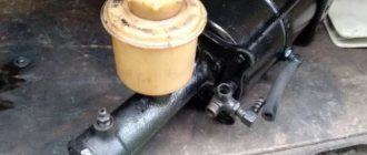
Vacuum booster
1 – vacuum booster housing;
2 – amplifier housing cup; 3 – rod; 4 – adjusting bolt; 5 – rod seal; 6 – sealing ring of the master cylinder flange; 7 – diaphragm return spring; 8 – amplifier pin; 9 – tip mounting flange; 10 – valve; 11 – hose tip; 12 – diaphragm; 13 – amplifier housing cover; 14 – sealing cover; 15 – piston; 16 – protective cover of the valve body; 17 – air filter; 18 – pusher; 19 – pusher return spring; 20 – valve spring; 21 – valve; 22 – valve body bushing; 23 – rod buffer; 24 – valve body; A – vacuum chamber; B – atmospheric chamber; C, D – channels The rubber diaphragm 12 together with the valve body 24 divides the cavity of the vacuum amplifier into two chambers: vacuum A and atmospheric B. Chamber A is connected to the engine inlet pipe through the check valve of the tip 11 and a hose.
The 24 valve body is plastic. At the exit from the cover, it is sealed with a corrugated protective cover 16. The valve body contains the main cylinder drive rod 3 with a support sleeve, rod buffer 23, valve body piston 15, valve assembly 21, pusher and valve return springs 19 and 20, air filter 17 , pusher 18.
When you press the pedal, the pusher 18, the piston 15, and after them the valve 21 move until it stops against the seat of the valve body. In this case, cameras A and B are separated. As the piston moves further, its seat moves away from the valve and through the resulting gap, chamber B is connected to the atmosphere. The air entering through filter 17, the gap between the piston and the valve and channel D creates pressure on the diaphragm 12. Due to the difference in pressure in chambers A and B, the valve body moves along with the rod 3, which acts on the piston of the main cylinder.
When the pedal is released, valve 21 moves away from the body seat and through the resulting gap and channel C of chambers A and B communicate with each other.
Problems and their solutions
There are several common problems associated with brakes on a VAZ 2110 car. The reasons for their occurrence may be different, but the solution is always the same - timely and high-quality repairs.
- The brakes have completely lost their effectiveness, pressing the pedal does not cause any reaction. In such a situation, it is categorically impossible to drive anywhere under your own power, even if we are talking about a trip to a service station? How do you brake? About a wall or pillar? Call a tow truck and start repairs. In some situations, the problem can be solved on the spot, but these are temporary measures.
- During braking, strong vibrations are observed, most often in the steering column. At the same time, when you press the pedal, it is difficult to hold the steering wheel in your hands. There may be several reasons for this:
- If you have non-ventilated discs installed, similar situations may arise during rain or when braking through a puddle. Such devices do not like moisture, so to get rid of vibrations, replace the disks with ventilated ones;
- Another cause of vibrations is faulty drums. If there are dark spots on the working surface of the drums, the unit wears unevenly. Immediate repair or complete replacement of mechanisms is required;
- Be sure to check for signs of deformation on the front brake discs. They often cause vibrations.
- Pressing the brake pedal is very tight, it is physically difficult to press it properly. The reasons are also different:
- The vacuum booster air filter may be clogged, causing the brake pedal to feel stiff;
- The vacuum booster itself is faulty, the tips and diaphragm are damaged, the movement of the check valve is disrupted, and there is damage to the connecting hose. Each of these problems causes the pedal to become stiff. The solution is to repair failed components;
- The pads can wear out over time, which is also often the cause of a stiff pedal.
- Pressing the brake causes a hissing sound. Check at what point the hissing starts. If you directly press the brake pedal, then the vacuum booster is checked first. Depending on the degree of damage, it is replaced or repaired. If there is a hissing sound when you release the brake pedal, then nothing bad happens. This is a completely natural phenomenon. Of course, if the hissing is not very loud and intense.
As you can see, the brake system of the VAZ 2110 car is far from perfect in its factory version, but it performs its functions effectively and reliably. All possible malfunctions can easily be fixed independently, but in some situations it is advisable to contact a professional service station.
Didn't find the information you are looking for? on our forum.
Pressure regulator drive
1 – pressure regulator; 2, 16 – pressure regulator mounting bolts; 3 – bracket for the pressure regulator drive lever; 4 – pin; 5 – pressure regulator drive lever; 6 – axis of the pressure regulator drive lever; 7 – lever spring; 8 – body bracket; 9 – pressure regulator mounting bracket; 10 – elastic lever of the pressure regulator drive; 11 – earring; 12 – earring bracket; 13 – washer; 14 – retaining ring; 15 – bracket pin; A, B, C – holes
Pressure regulator
1 – pressure regulator housing; 2 – piston; 3 – protective cap; 4, 8 – retaining rings; 5 – piston sleeve; 6 – piston spring; 7 – body bushing; 9, 22 – support washers; 10 – sealing rings of the pusher; 11 – support plate; 12 – pusher bushing spring; 13 – valve seat sealing ring; 14 – valve seat; 15 – sealing gasket; 16 – plug; 17 – valve spring; 18 – valve; 19 – pusher bushing; 20 – pusher; 21 – piston head seal; 23 – piston rod seal; 24 – plug; A, D – chambers connected to the main cylinder; B, C – chambers connected to the wheel cylinders of the rear brakes; K, M, N – gaps
The pressure regulator regulates the pressure in the hydraulic drive of the rear wheel brakes depending on the load on the rear axle of the vehicle. It is included in both circuits of the brake system and through it brake fluid flows to both rear brake mechanisms.
Pressure regulator 1 (Fig. Pressure regulator drive) is attached to bracket 9 with two bolts 2 and 16. At the same time, front bolt 2 simultaneously secures fork bracket 3 of lever 5 of the pressure regulator drive. A double-arm lever 5 is hinged on the pin of this bracket with a pin 4. Its upper arm is connected to an elastic lever 10, the other end of which is pivotally connected to the rear suspension arm bracket through an earring 11.
Bracket 3 together with lever 5 can be moved relative to the pressure regulator due to the oval holes for the fastening bolt. This regulates the force with which lever 5 acts on the regulator piston (see subsection 6.4.2). The regulator has four chambers: A and D (Fig. Pressure regulator) are connected to the main cylinder, B to the left, and C to the right wheel cylinders of the rear brakes.
In the initial position of the brake pedal, piston 2 (see Fig. Pressure regulator) is pressed by lever 5 (see Fig. Pressure regulator drive) through leaf spring 7 to pusher 20 (see Fig. Pressure regulator), which is pressed against the saddle under this force 14 of valve 18. In this case, valve 18 is pressed away from the seat and a gap H is formed, as well as a gap K between the piston head and seal 21. Through these gaps, chambers A and D communicate with chambers B and C.
When you press the brake pedal, fluid flows through gaps K and H and chambers B and C into the wheel cylinders of the brake mechanisms. As the fluid pressure increases, the force on the piston increases, tending to push it out of the housing. When the force from the liquid pressure exceeds the force from the elastic lever, the piston begins to move out of the body, and after it, under the action of springs 12 and 17, the pusher 20 moves together with the sleeve 19 and rings 10. In this case, the gap M increases, and the gaps H and K decrease . When the gap H is completely selected and the valve 18 isolates chamber D from chamber C, the pusher 20, together with the parts located on it, stops moving after the piston. Now the pressure in chamber C will vary depending on the pressure in chamber B. With a further increase in the force on the brake pedal, the pressure in chambers D, B and A increases, piston 2 continues to move out of the body, and sleeve 19 together with o-rings 10 and plate 11 under increasing pressure in chamber B, it shifts towards plug 16. At the same time, the gap M begins to decrease. Due to the decrease in the volume of chamber C, the pressure in it, and therefore in the brake drive, increases and will be practically equal to the pressure in chamber B. When the gap K becomes zero, the pressure in chamber B, and therefore in chamber C, will increase less degree than the pressure in chamber A due to throttling of the liquid between the piston head and seal 21. The relationship between the pressure in chambers B and A is determined by the ratio of the difference in the areas of the head and piston rod to the area of the head.
As the vehicle load increases, the elastic lever 10 (see Fig. Pressure regulator drive) is loaded more and the force from lever 5 on the piston increases, that is, the moment of contact between the piston head and seal 21 (see Fig. Pressure regulator) is achieved at greater pressure in the main brake cylinder. Thus, the effectiveness of the rear brakes increases with increasing load.
If the brake circuit “left front – right rear brake” fails, the o-rings 10, bushing 19, under the fluid pressure in chamber B, will move towards the plug 16 until the plate 11 rests on the seat 14. The pressure in the rear brake will be regulated by part of the regulator, which includes piston 2 with seal 21 and bushing 7. The operation of this part of the regulator, in the event of a failure of the said circuit, is similar to the operation with a working system. The nature of the change in pressure at the outlet of the regulator is the same as with a working system.
If the brake circuit “right front – left rear brake” fails, the pressure of the brake fluid forces the pusher 20 with the bushing 19 and sealing rings 10 toward the piston, pushing it out of the housing. The M gap increases and the H gap decreases. When valve 18 touches seat 14, the increase in pressure in chamber C stops, that is, the regulator in this case works as a pressure limiter. However, the achieved pressure is sufficient for reliable operation of the rear brake.
There is a hole in housing 1, closed by plug 24. Liquid leakage from under the plug when it is squeezed out indicates a leak in rings 10.
Device
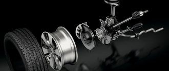
Hydraulic brakes are installed on the machine and operate generally reliably. They are double-circuit and have a diagonal distribution. That is, if one part suddenly fails, then braking by another circuit is possible. For the sake of safety, the VAZ 2110 brakes operate diagonally, one circuit is the right front and left rear wheels, the other is also diagonal.
This device allows you to brake efficiently (without skidding and other troubles) even in the event of a malfunction, if the brakes in one of the circuits are lost.
Let's consider the design of the brake system. The hydraulic drive includes a vacuum booster, as well as a dual-circuit regulator that creates pressure in the rear brakes.
In addition, the hydraulic drive is equipped with pipelines divided into two circuits, hoses and brake mechanisms that provide braking to the front and rear mechanisms.
The hydraulic drive is activated by a pedal located in the cabin (middle). Here are the main components of the hydraulic drive:
- Vacuum booster.
It is designed in such a way that it creates pressure on the master cylinder piston, and thus causes braking; Vacuum brake booster - Pressure regulator drive.
It is through it that the working brake fluid flows to the rear brake mechanisms; Brake pressure regulator drive - The pressure regulator itself.
Already from the name it is clear that this device is responsible for the force of pressure, its decrease or increase. He does this depending on how loaded the rear axle of the car is; Pressure regulator - Main cylinder with pistons, equipped with a reservoir.
The filler neck of the tank is equipped with an emergency fuel level sensor; Master brake cylinder - Brake mechanism for the front wheel.
Its main parts are the disc, pads and wheel cylinders. The mechanism also provides an indicator to prevent complete wear and malfunction of the linings; Front wheel brake - Brake mechanism for the rear wheel.
Unlike the front disc brakes, the rear ones are drum brakes. This is the factory configuration. However, many car owners believe that their device does not provide high-quality braking, and change them to disc ones. Rear wheel brake
The brakes require attention. Without waiting for the warning light to come on, indicating a critical level of fuel fluid or wear of the linings, and even more so, without allowing the brakes to completely disappear, you need to carry out preventive checks.
Particular attention should be paid to all connections and hoses, since the “escaped” brake fluid will not make it possible to brake, and from here it’s not far from tragedy.
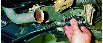
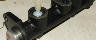
Master cylinder with reservoir
1 – main cylinder body; 2 – low pressure sealing ring; 3 – drive piston of the “left front–right rear brake” circuit; 4 – spacer ring; 5 – high pressure sealing ring; 6 – pressure spring of the sealing ring; 7 – spring plate; 8 – piston return spring; 9 – washer; 10 – locking screw; 11 – drive piston of the “right front–left rear brake” circuit; 12 – connecting sleeve; 13 – tank; 14 – brake fluid emergency level sensor; A – gap
Master cylinder with sequential pistons. A tank 13 is mounted on the master cylinder body, in the filler neck of which a sensor 14 for emergency brake fluid level is installed. The high pressure O-rings 5 and the rear wheel cylinder rings are interchangeable.
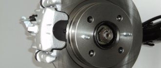
Front wheel brake
1 – brake disc; 2 – pad guide; 3 – caliper; 4 – brake pads; 5 – cylinder; 6 – piston; 7 – pad wear indicator; 8 – sealing ring; 9 – protective cover of the guide pin; 10 – guide pin; 11 – protective casing
The front wheel brake mechanism is disc, with automatic adjustment of the gap between the pads and the disc, with a floating caliper and a brake pad wear indicator. The bracket is formed by a caliper 3 and a wheel cylinder 5, which are tightened with bolts. The movable bracket is bolted to pins 10, which are installed in the holes of the guide 2 of the pads. Lubricant is placed in these holes, rubber covers 9 are installed between the pins and the pad guide. Brake pads 4 are pressed against the grooves of the guide by springs, the inner one of which has a lining wear indicator 7.
A piston 6 with a sealing ring 8 is installed in the cavity of the cylinder 5. Due to the elasticity of this ring, the optimal gap between the pads and the disk is maintained.
Replacing rear brake pads on VAZ-2110, 2111, 2112
One of the most popular models on the domestic market today is still a simple, practical ten.
This machine began to be designed back in 1983 as part of a new plant development project. Assembled on the basis of the VAZ-2108, the model became its improved version, which received not only a modern image, but also a richer technical content.
But, like the eight, and like all AvtoVAZ cars, the ten also has a number of shortcomings. In particular, these are weak rear brake pads, which quite often fail and need to be replaced.
We will talk about how to replace parts yourself in this article.
Wheel cylinder
1 – block stop; 2 – protective cap; 3 – cylinder body; 4 – piston; 5 – seal; 6 – support plate; 7 – spring; 8 – crackers; 9 – thrust ring; 10 – thrust screw; 11 – fitting; A – slot on the thrust ring
The rear wheel brake mechanism (Fig. Rear wheel brake mechanism) is drum-type, with automatic adjustment of the gap between the shoes and the drum. The automatic clearance adjustment device is located in the wheel cylinder. Its main element is a split thrust ring 9 (Fig. Wheel cylinder), installed on the piston 4 between the shoulder of the thrust screw 10 and two nuts 8 with a gap of 1.25–1.65 mm.
The thrust rings 9 are inserted into the cylinder with tension, providing a shear force of the ring along the cylinder mirror of at least 343 N (35 kgf), which exceeds the force on the piston from tension springs 3 and 7 (see Fig. Brake mechanism of the rear wheel) of the brake pads.
When, due to wear of the linings, the gap of 1.25–1.65 mm is completely removed, the shoulder on the thrust screw 10 (see Fig. Wheel cylinder) is pressed against the shoulder of the ring 9, as a result of which the thrust ring moves after the piston by the amount of wear. When the braking stops, the pistons are moved by the force of the tension springs until the cracks stop against the shoulder of the thrust ring. This automatically maintains the optimal clearance between the pads and the drum.
Alarm Signals
The following symptoms are quite unsafe, please note:
- If the brakes are completely gone, then it’s clear that you can’t go any further, even to a service station! If independent repairs on site are beyond your capabilities, or simply impossible, you need to call a tow truck;
- When braking there is a strong vibration, especially felt in the steering column. You press the pedal, and it’s just hard to hold the steering wheel in your hands. There can be several reasons for vibration: • Many argue that vibration can occur due to the fact that there are non-ventilated disks. Their design is such that they really don’t like it when braking occurs in the rain, or even right in a puddle. No repair will help here - you need to replace the disks with ventilated ones; • Vibration may also occur if there is a problem with the rear drums. If upon inspection you find dark spots on the working surface, this indicates uneven wear. The vibration is usually very strong. Such drums need urgent repairs, and possibly replacement with disc brakes; • Check the front brake discs for deformation. At the same time, vibration is also observed.
- The brake pedal is too tight. There may also be several reasons for this: • A clogged air filter for the vacuum booster can cause the pedal to become stiff; • Check the vacuum booster itself. Its possible malfunctions are destruction of the diaphragm, tip, sticking of the check valve, damage to the hose connecting the intake manifold to the amplifier. In all these cases, a stiff pedal syndrome may occur, and repair of any of the indicated faults is necessary; • Also, the pedal may become stiffer as the pads wear, check them too.
- Hisses when you press the brake. If it hisses exactly when you press the pedal, you need to urgently check the vacuum booster, and then decide whether it needs repair or replacement. But if it hisses when you release the brake, then this is a normal phenomenon. Unless, of course, the hiss is too obvious.
Parking brake system drive
The mechanically actuated parking brake system acts on the brake mechanisms of the rear wheels. The parking brake drive consists of lever 2, adjusting rod 4, equalizer 5, cable 8, lever 10 (see Fig. Rear wheel brake mechanism), manual pad drive and expansion bar 8.
1 – protective cap; 2 – sensor housing; 3 – sensor base; 4 – sealing ring; 5 – clamping ring; 6 – reflector; 7 – pusher; 8 – bushing; 9 – float; 10 – fixed contacts; 11 – moving contact
Mechanical brake fluid emergency level sensor. The sensor body 2 with a seal 4 and the base 3 with a reflector 6 are pressed by a clamping ring 5 to the end of the tank neck.
A pusher 7 passes through the hole in the base, connected to the float 9 by means of a sleeve 8. There is a moving contact 11 on the pusher, and fixed contacts 10 are located on the sensor body. The contact cavity is sealed with a protective cap 1. When the level of brake fluid in the reservoir drops to the maximum permissible, the moveable the contact moves down onto the fixed contacts and closes the circuit of the hazard warning lamp on the instrument panel.
General information about electrical equipment of VAZ 2110, 2112, 21102
Steering VAZ 2110 (2112)