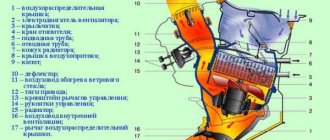
A high-quality color diagram of the electrical equipment of the domestic passenger car VAZ-21074 is provided to help auto electricians and service stations. Model 21074 is an improved modification of the VAZ-2107. The “seventy-four” is equipped with the same 1.6-liter engine, but the carburetor is replaced with an injector. Some elements of the circuit are installed not on all, but only on part of the produced cars of this model. At the end of the article, fuses and the circuits they protect are shown. Schemes are enlarged by clicking.
Electrical equipment VAZ-21074
- 1- block headlights;
- 2- side direction indicators;
- 3- rechargeable battery;
- 4- starter activation relay;
- 5- carburetor electro-pneumatic valve;
- 6- carburetor microswitch;
- 7- generator 37.3701;
- 8- gearmotors for headlight cleaners*;
- 9- fan motor activation sensor;
- 10- electric motor of the engine cooling system fan;
- 11- sound signals;
- 12- ignition distributor;
- 13- spark plugs;
- 14- starter VAZ-21074;
- 15- coolant temperature indicator sensor;
- 16- engine compartment lighting lamp;
- 17- low oil pressure indicator sensor;
- 18- low brake fluid level indicator sensor;
- 19- windshield wiper gearmotor;
- 20- carburetor electro-pneumatic valve control unit;
- 21- ignition coil;
- 22- electric motor of the headlight washer pump*;
- 23- electric motor of the windshield washer pump;
- 24- mounting block;
- 25- windshield wiper relay;
- 26- hazard warning and direction indicator relays;
- 27- brake light switch;
- 28- reversing light switch;
- 29- ignition relay;
- 30- ignition switch;
- 31- three-lever switch;
- 32- alarm switch;
- 33-plug socket for a portable lamp**;
- 34- heater fan switch;
- 35 - additional resistor of the heater electric motor;
- 36 - indicator lamp for turning on the heated rear window;
- 37 - indicator lamp for insufficient brake fluid level;
- 38 - signaling unit;
- 39- heater fan electric motor;
- 40 - glove box lighting lamp;
- 41 - lamp switch on the front door pillars;
- 42- switch for alarm lights of open front doors***;
- 43- alarm lights for open front doors***;
- 44- connecting block;
- 45- cigarette lighter;
- 46- watch VAZ-21074;
- 47- switch for instrument lighting lamps;
- 48- diode for checking the serviceability of the warning lamp for insufficient brake fluid level;
- 49 - fuel level indicator;
- 50 - fuel reserve indicator lamp;
- 51- speedometer;
- 52 - turn signal indicator lamp;
- 53- indicator lamp for closing the carburetor air damper;
- 54 - battery charging indicator lamp;
- 55- carburetor air damper closed warning switch;
- 56 - instrument cluster;
- 57- econometrician;
- 58- courtesy light switches on the rear door pillars;
- 59 - coolant temperature indicator;
- 60 - tachometer 21074;
- 61- parking brake indicator lamp;
- 62 - low oil pressure indicator lamp;
- 63- high beam indicator lamp;
- 64- indicator lamp for turning on external lighting;
- 65-voltmeter;
- 66- parking brake indicator switch;
- 67- switch for external lighting lamps;
- 68- rear window heating element switch with backlight;
- 69- switch for rear fog lights with on/off indicator*;
- 70 - fog light circuit fuse;
- 71- lampshade;
- 72 - rear lights VAZ 21074;
- 73 - level indicator and fuel reserve sensor;
- 74- pads for connecting to the rear window heating element*;
- 75 - license plate lights.
Work order
- We place the car on a viewing hole or overpass and secure it with the parking brake.
- Open the hood and disconnect the ground wire from the battery.
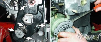
- Using a 10mm socket, unscrew the bolt of the lower fastening of the starter heat shield.
- We dismantle the air filter housing and the warm air supply hose (for injection units, remove the fastenings of the intake pipeline).
- Using a socket wrench with a 13 mm extension, unscrew the 3 bolts securing the starter housing. It is better to unscrew the bottom bolt from the inspection hole.
- Using a 13mm wrench, unscrew the nut (on the injection engine there are two nuts) securing the starter shield. Let's take it out.
- Using a socket wrench with a 13 mm extension, unscrew the 3 bolts securing the starter housing. It is better to unscrew the bottom bolt from the inspection hole.
- Using the same tool, unscrew the nut securing the tip of the wire going to the “+” battery.
- Disconnect the start relay wire.
- We remove the starter from the rear wall of the engine compartment.
- We install a new starter in its place.
- We carry out installation work in reverse order.
What to do first?
Disassembling the mechanism is not a priority task, since the starter’s power supply is connected to the battery, so you need to start with it. If the car is not too old, it is unlikely that the problems will lie in the design of the starter itself. It is enough to clean the contacts of the battery or the device itself for everything to work again in the desired mode.
Difficulties begin when the machine has worked for a long time and its operation has not been delicate. If, after a complete check of the electrical equipment of your VAZ 2107, the starter still does not start or continues to work intermittently, then the reason is inside the device and it is necessary to remove and disassemble the starter. On this model, both in carburetor and injection versions, it is installed rather inconveniently. To get to it normally, you will have to drive the car onto an overpass or inspection hole.
Disassembling the VAZ 2107 starter
After the ignition is turned off, you can begin the “operation”. It must be done in the following order:
- remove the ground terminal from the battery;
- if there is a protective mud casing at the bottom, then it must be dismantled;
- remove the electrical wires from the solenoid relay;
- unscrew the three mounting bolts (two upper, one lower);
- remove the starter.
As you can see, nothing complicated. The only thing is that in the case of an injection model, mechanics advise removing the inlet pipe extensions as well. Now we have to disassemble the device itself.
VAZ 21074 engine control system diagram
Wiring diagram of electrical connections of ECM VAZ 21074 - circuit elements. 1 – controller connector; 2 – mass air flow sensor; 3 – coolant temperature sensor; 4 – crankshaft position sensor; 5 – throttle position sensor; 6 – oxygen concentration sensor; 7 – speed sensor; 8 – ignition module; 9 – solenoid valve for purge of the adsorber; 10 – electric fan relay; 11 – electric fuel pump relay; 12 – main relay; 13 – fuse for the power circuit of the electric fuel pump relay: 14 – fuse for the power circuit of the main relay; 15 – fuse link; 16-fuse protecting the constant power supply circuit of the controller; 17 – diode; 18 – idle speed regulator; 19 – nozzles; X1 – diagnostic block; X2 – connection block to the vehicle electrical system.
Summary
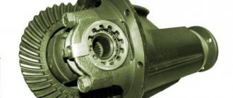
It is worth noting that a starter without a gearbox has a larger gap between the armature and the stator than a geared counterpart. For this reason, its permissible shaft misalignment is also greater.
And one more piece of advice. If the starter is still disassembled, then it would be a good idea to replace the brushes. The parts are cheap, so waiting for them to fail and then dealing with them separately is not worth it. Of course, for all the operations described above, at least a little experience is required. And, as you know, he is a profitable business. In the end, to get it you have to try. Go for it!
Fuse box VAZ-21074 injector
- 1-Rear window heating relay
- 2-Relay for headlight cleaners and washers (if equipped)
- 3-relay or signal jumper (if there is no external relay)
- 4-relay or jumper for cooling fan
- 5-high beam relay
- 6-low beam relay
- F1-F17-Fuses
- 1 (8A) Rear lights (reversing light). Heater electric motor. Warning lamp and rear window heating relay.
- 2 (8A) Electric motors for windshield wiper and washer. Electric motors for headlight cleaners and washers. Windshield wiper relay. Wiper relay and
- headlight washer (contacts).
- 3 (8A) Reserve.
- 4 (8A) Reserve.
- 5 (16A) Rear window heating element and heating relay (contacts)
- 6 (8A) Cigarette lighter. Portable lamp socket. Watch. Front door open warning lamps
- 7 (16A) Sound signals and relay for turning on sound signals. Engine cooling fan electric motor and motor activation relay.
- 8 (8A) Direction indicators in hazard warning mode. Switch and relay-interrupter for direction indicators and hazard warning lights in emergency mode.
- 9 (8A) Generator voltage regulator.
- 10 (8A) Direction indicators in turn indication mode and the corresponding warning lamp. Fan motor activation relay (winding). Control devices. Battery charge indicator lamp. Indicator lamps for fuel reserve, oil pressure, parking brake and brake fluid level. Parking brake warning light relay. Carburetor pneumatic valve control system
- 11 (8A) Rear lights (brake lamps). Body interior lighting lamp.
- 12 (8A) Right headlight. Coil of the relay for turning on the headlight cleaners (with the high beams on)
- 13 (8A) Left headlight. Indicator lamp for turning on the high beam headlights.
- 14 (8A) Left headlight (side light). Right rear light (side light). License plate lights. Engine compartment lamp. Indicator lamp for turning on the side light.
- 15 (8A) Right headlight (side light). Left rear light (side light). Cigarette lighter lamp. Instrument lighting lamps. Glove compartment lamp
- 16 (8A) Right headlight (low beam). Coil of the relay for turning on the headlight cleaners.
- 17 (8A) Left headlight (low beam).
Starter performance check and repair
First of all, you should clean the starter housing from dirt, which inevitably accumulates on it during the operation of the car. Then connect the mechanism to the battery: the “negative” wire to the starter housing, the “positive” wire to the contact of the traction relay. A characteristic click should follow, and a drive gear will appear in the front “cutout” of the casing. Now use an ohmmeter and check the armature windings for opens and shorts. To do this, you need to open the cover at the back of the starter and remove the brush holders with brushes.
Then connect the ohmmeter with one end to the armature body, and the other - alternately to the sectors of the winding. If there are no short circuits or breaks, the instrument needle will fluctuate from a minimum value of 10 kOhm and above.
Now comes the integrity check of the stator winding (in other words, located inside the housing, along the walls of the cylinder). Here you simply connect the ohmmeter contacts to the copper wire terminals. The arrow of the measuring device should “lie” in the area of the highest value if there are no problems. If there are breaks or short circuits in the windings of the starter or solenoid relay, there is no point in bothering with repairs if you have never dealt with electromechanics and have not encountered the technology of manufacturing electric coils. It is best (and easier) to purchase a complete starter and install a new starter.
Checking the integrity of the stator winding
An operation that can really be called a repair is replacing brushes. You can easily find out that they are erased during diagnostics. It is enough to turn the starter on its side when it is connected to the battery and turns properly. If the unit immediately stalls, brush wear is to blame. Replacing parts is simple and accessible even to a beginner. It was already mentioned above that it is enough to remove the cover at the rear of the starter. When the brush holder is removed, the springs in it will themselves push out the brushes, which will hang on the wires. Replacement is a matter of minutes.
The main thing is to never allow oil or fuel to come into contact with brushes or wire windings. Electrics do not tolerate moisture or grease. Therefore, during any operations with starter parts, especially when assembling it, act carefully and, if possible, stay away from liquids and fuels and lubricants.
There is one rare malfunction when the starter turns on, but nothing turns. In this case, the bendix is to blame - a device that prevents the teeth of the drive gear from sharply hitting the flywheel. Its main malfunctions are wear of the rollers, the gear itself, weakening of the pressure spring or unsuitability of the lubricant. This part is inexpensive, changes quickly, and therefore there is no point in bothering with repairs. It is better to purchase it in a store; replacement is done on the “return” when the starter is being assembled.
Sometimes the armature bushings need to be replaced, but this is extremely rare because they are made of very reliable material and wear only appears after a really long period of use. There are only two of them - in the toe and back cover. The process of knocking the bushings out of their seats is usually confusing, but by choosing the right attachment, you won’t ruin anything. Next, a part of the required diameter is lubricated and pushed into the hole. If things get tight, don’t use more force; it’s better to sand the bushing body and try again, otherwise the socket may simply burst.
- “They moved my car onto the lawn, and it turned out to be my fault” - the story of a motorist who suffered because of utility workers
- 6 Mercedes that were officially imported to the USSR
- 4 ways to deceive drivers in tire shops
- 4 mistakes when transporting cargo on the roof of a car that can lead to serious damage
- Advice from psychologists: how not to look at a traffic police inspector to avoid problems
- Celebrities who collect cars
- I found out why people buy used oil - you need to be careful
- “I was charged money for an accident in Volgograd, although I did not have an accident and had never been to this city,” is the story of our subscriber
Electrical diagram VAZ-2107 carburetor
Electrical diagram of VAZ 2107, 21074 produced in 1988-2001 with generator 37.3701
- block headlights
- side direction indicators
- accumulator battery
- starter relay
- carburetor electro-pneumatic valve
- carburetor microswitch
- generator 37.3701
- gearmotors for headlight cleaners *
- Fan motor switch sensor
- engine cooling fan motor
- sound signals
- distributor
- spark plug
- starter
- coolant temperature gauge sensor
- engine compartment lamp
- low oil pressure warning sensor
- low brake fluid level indicator sensor
- windshield wiper motor
- carburetor electro-pneumatic valve control unit
- ignition coil
- headlight washer pump motor *
- windshield washer pump motor
- mounting block
- windshield wiper relay
- hazard warning and direction indicator relay
- brake light switch
- reverse light switch
- ignition relay
- ignition switch
- three lever switch
- hazard switch
- socket for portable lamp**
- heater fan switch
- additional resistor for the electric motor of the heater (stove)
- rear window heating indicator lamp
- low brake fluid level warning lamp
- signaling unit
- heater fan electric motor
- glove compartment lamp
- light switches on the front door pillars
- switches for warning lights of open front doors ***
- front door open warning lights ***
- connection block
- cigarette lighter
- watch
- instrument light switch
- diode for checking the serviceability of the low brake fluid level indicator lamp
- fuel level indicator
- fuel reserve indicator lamp
- speedometer
- turn signal indicator lamp
- carburetor choke indicator lamp
- battery charge indicator lamp
- carburetor choke warning switch
- instrument cluster
- econometrician
- light switches on the rear door pillars
- coolant temperature gauge
- tachometer
- parking brake indicator lamp ("handbrake")
- low oil pressure warning lamp
- high beam indicator lamp
- indicator lamp for turning on external lighting
- voltmeter
- parking brake indicator switch ("handbrake")
- outdoor light switch
- rear window heating switch with backlight
- rear fog light switch with on/off indicator *
- fog light circuit fuse
- lampshade ****
- tail lights
- level indicator and fuel reserve sensor
- connectors for connecting to the rear window heating element *
- license plate lights 2107
Wiring diagram VAZ-2107 carburetor - full view:
How to repair a car starter with your own hands?
The VAZ-2107 starter repair procedure includes two stages. We are talking about disassembling the device and troubleshooting its component parts.
Disassembling the device
When disassembling the device, it is necessary to replace the defective parts with new ones:
- First, unscrew the nut located on the lower contact screw of the solenoid relay. The output with the windings is disconnected from the screw; for this, the spring element is dismantled, as well as two washers. Three bolts are unscrewed, which secure the relay itself to the mechanism cover. The screws are located on the drive side. Holding the anchor mechanism, the retractor relay is removed.
- The spring element is removed from the anchor mechanism. The anchor is pulled upward and disengaged from the lever of the drive device. The element is retrieved.
- The two bolts securing the protective casing of the device are unscrewed, then the protection is removed. Using a screwdriver, pry off the retaining ring of the rotor mechanism pulley, as well as the washer. The two tightening screws are unscrewed, after which the cover is disconnected from the drive device side from the mechanism body. Dismantling is carried out together with the stator device.
- The bolts that secure the winding of the stator mechanism and the connecting electrical circuit are unscrewed. The jumpers are disconnected from the brush holder. The insulating tube is dismantled.
- The cover of the starter mechanism on the side of the commutator device is disconnected from the housing.
- The winding jumper is removed from the mechanism for fixing the brushes. The stator brushes and the spring element are dismantled; these parts must be pryed off using a screwdriver.
- The rear bearing device, made in the form of a bushing, is pressed out. This part is located on the rear cover of the starter mechanism. To remove it, you will need a mandrel of the appropriate diameter. The cotter pin of the drive mechanism lever axis is also removed; it is located in the front cover. To perform this task, you will need a flat blade screwdriver.
- The rubber plug is removed, after which the lever of the drive device is removed from engagement with the bendicosm. The anchor mechanism with the clutch is being dismantled.
- Then you need to move the thrust washer, which is fixed on the pulley of the anchor element. It moves towards the coupling of the drive device. The locking element, made in the form of a ring, is dismantled; to do this, it must be opened using two screwdrivers. If you have forceps, it will be more convenient to use this tool. The clutch is removed from the drive.
- The front bearing is dismantled from the mechanism cover; to do this, it must be pressed out. The procedure is performed from the drive device side.
The Auto Repair and Maintenance channel showed the procedure for self-disassembling the starter mechanism for classic VAZ models.
Defective starter parts
Defects of constituent elements are performed as follows:
- First, the height of the brushes on the mechanism is measured. Over time, parts wear out. Therefore, if the height is 1.2 cm or less, the brushes must be replaced.
- A visual check of the winding condition is performed. There should be no signs of damage to the insulation or burnout. The poles of the stator device must be free of mechanical damage in the form of cracks and other defects. If present, the winding must be replaced or rewinded.
- The bushing on the cover from the side of the collector device is inspected. It must not be worn, cracks or any other defects are not allowed.
- A visual check of the anchor element is performed. It is not allowed to have burrs or nicks, in particular, we are talking about splines and the shaft. There should be no signs of burning on the armature commutator mechanism, otherwise it must be replaced.
- Then you need to check how easily the retractor anchor device moves. You need to make sure that the contact screws of the plate are closed; for this you will need an ohmmeter or multimeter.
- The clutch gears of the drive device are inspected. There should be no signs of wear on its teeth.
- Perform a visual check of the drive arm. There are no traces of cracks or other defects on it, as well as wear of the grooves.
One of the weakest devices in the VAZ-2017 starter is the bendix, but often it cannot be repaired, only replaced.
The altevaa TV channel talked about checking the windings in order to determine their faults and replace parts.
Assembly Features
The assembly procedure is performed in reverse order:
- If necessary, the surface of the armature commutator device is cleaned. For cleaning, use fine-grained sandpaper. After cleaning, the collector mechanism must be blown with a compressed air stream, and also treated with fuel or an alcohol solution.
- Then the splined surface of the anchor element pulley is treated with motor fluid. Also subject to treatment are the pulley journals, the drive coupling gear and the bearing elements located in the device covers.
- When the assembly of the mechanism is completed, using a caliper, the axial clearance of the anchor device shaft is diagnosed. To do this, the shaft moves in one direction - to the commutator mechanism, and then in the other - to the drive. It is necessary to measure the difference in the parameters of the protrusion of the pulley from the cover on the side of the drive element. The gap should be no more than 0.5 mm.
Mounting block connection diagram
P1 — relay for turning on the heated rear window; P2 - relay for turning on the headlight cleaners and washer; P3 - relay for turning on sound signals; P4 - relay for switching on the electric motor of the engine cooling system fan; P5 - headlight high beam relay; P6 - low beam headlight relay; A - the order of conditional numbering of plugs in the mounting block blocks. The outer number with the letter “Ш” in the plug designation is the block number, and the inner number is the conventional number of the plug.
Starter components
To repair a part of any device, you need to understand what it consists of. So, for example, the design of the starter is as follows:
- anchor;
- frame;
- drive unit;
- relay. Connection to it is made using contact bolts, which are considered structural elements. Each of them consists of parts that are fairly easy to replace if necessary.
Remember that it is quite easy to repair the starter on a VAZ-2107 with your own hands. To do this, you need to know what exactly it consists of, as well as what it is intended for.
Schemes of individual blocks of the seven
Power supply system
Power plant starting system
1 - starter; 2 - relay; 3 — ignition switch; 4 - battery
Ignition system
1 - generator; 2 — ignition switch; 3 - distributor; 4 - breaker; 5 — candles; 6 - coil; 7 - battery
Contactless ignition system
External and internal lighting
Windshield wipers and washers
1 — electric motors of the windshield wiper; 2 — washer motor; 3 — mounting block; 4 — ignition switch; 5 - washer switch
Cooling Fan
1 — fan electric motor; 2 - sensor; 3 — mounting block; 4 - ignition relay; 5 - ignition switch.
Detailed installation process
In order to correctly install the starter, you must adhere to the following points:
1. Conduct a visual inspection of the device. 2. Installation of the device in its original place. First fasten with a long bolt, and then with two short ones. 3. Install the wire terminals and tighten the nuts. 4. Replace the battery. 5. Connect the terminals on the battery. 6. Install the braces coming from the intake pipe or air duct and air filter. 7. Replace the mudguard (if equipped).
After everything is done, you should start the engine. If everything works as expected, then the starter connection is made correctly. If the engine does not start, you should look for where the error was made.
Wires for connecting electrical appliances
| Connection type | Section, mm 2 | Insulation color |
| Negative terminal of the battery - vehicle ground (body, engine) | 16 | Black |
| Starter positive terminal - battery | 16 | Red |
| Positive contact of the generator - plus battery | 6 | Black |
| Generator - black connector | 6 | Black |
| Terminal on the generator “30” – white MB block | 4 | Pink |
| Starter connector “50” – starter relay | 4 | Red |
| Starter Start Relay - Black Connector | 4 | Brown |
| Ignition switch relay - black connector | 4 | Blue |
| Ignition switch output “50” – blue connector | 4 | Red |
| Ignition switch connector “30” – green connector | 4 | Pink |
| Right headlight plug - ground | 2,5 | Black |
| Left headlight plug - blue connector | 2,5 | Green, gray |
| Generator output “15” – yellow connector | 2,5 | Orange |
| Right headlight connector - ground | 2,5 | Black |
| Left headlight connector - white connector | 2,5 | Green |
| Radiator fan - ground | 2,5 | Black |
| Radiator Fan - Red Connector | 2,5 | Blue |
| Ignition switch output “30/1” – ignition switch relay | 2,5 | Brown |
| Ignition switch contact “15” – single-pin connector | 2,5 | Blue |
| Right headlight - black connector | 2,5 | Grey |
| Ignition switch connector “INT” – black connector | 2,5 | Black |
| Six-pin block of the steering column switch - “ground” | 2,5 | Black |
| Two-pin block of the steering column switch - glove box illumination lamp | 1,5 | Black |
| Glove compartment light - cigarette lighter | 1,5 | Black |
| Cigarette lighter - blue block connector | 1,5 | Blue, red |
| Rear window defroster - white connector | 1,5 | Grey |
troubleshooting
In order to correctly determine where to start, you should think about what could be the reason that the starter does not work:
- If, after you turn the key in the ignition, the engine stubbornly refuses to start, you should check the light bulbs located on the instrument panel. If they burn weakly or go out completely, most likely the reason lies in a non-functioning battery. Or it may simply be discharged. We pick up a tester and check the battery capacity and voltage;
- if the battery is fully operational, you need to check what position the speed switch is in and move it to the “P” position;
- The next thing to figure out is whether the power from the ignition switch is getting directly to the starter.
There are two ways to do the last step.
Method 1. A wire made of copper with a cross-section of 2.5 mm is inserted into the open connector. One end goes to the starter and the other to the battery terminal. Thanks to this method, it is possible to simulate ignition.
Method 2: This verification method will require two people. One of them will turn the key in the ignition switch, while the second will touch the tip of the wire that comes from the unloading relay with a control probe. If the warning light comes on during this procedure, this indicates that there are no problems in the ignition switch, as well as in the relay.
Car wiring diagram
1 – radiator fan drive motor; 2 – relay and fuse block (mounting block); idle speed sensor; 4 – engine control unit; 5 – potentiometer; 6 – set of spark plugs; 7 – ignition control unit; 8 – electronic crankshaft sensor; 9 – electric fuel pump; 10 – tachometer 2107; 11 – lamp for monitoring the health of electronic systems; 12 – ignition system control relay; 13 – speed sensor; 14 – diagnostic connector; 15 – set of injectors; 16 – adsorber solenoid valve; 17, 18, 19 – fuse block protecting the injection system circuits; 21 – electronic fuel pump control relay; 22 – electronic relay for controlling the intake pipe heating system; 23 – intake pipe heating system; 24 – fuse protecting the heater circuit; 25 – electronic oxygen level sensor; 26 – cooling system temperature control sensor; 27 – electronic air damper sensor; 28 – air temperature sensor; 29 – pressure control sensor.
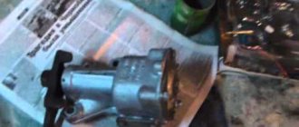
Cleaning nickels from carbon deposits on the solenoid relay
All this is best done on a removed part, which you can read about here. After this, you need to use a deep socket and a wrench to unscrew the three nuts securing the cover to the body, as is clearly shown in the photo below:
When all the nuts are unscrewed, you need to press on all the bolts from the same side and pull them out from the back:
Now carefully fold back the relay cover, but not all the way, as the wire will get in the way:
Pay attention to the central copper plate: it will definitely need to be cleaned of plaque and carbon deposits, if any. Also, you need to unscrew the nickels themselves (two in total) by unscrewing the two nuts on the outside of the cover:
And then you can take them out from there with your hands, from the back side:
Also clean them thoroughly with fine sandpaper until shiny:
After completing this simple procedure, you can put everything back in place in the reverse order. If the problem was precisely the burnt nickels, then it will definitely disappear!
Fuse and relay diagram 2107
On newer “sevens” a block with 17 fuses and 6 relays is installed. VAZ 2107 fuses on the “new” unit protect the following electrical circuits and devices:
- Reversing lamps, heater fan, rear window defroster warning lamp and relay, rear wiper motor and rear washer pump.
- Electric motor for front wipers.
- Reserve socket.
- Reserve socket.
- Power supply for heated rear window.
- Clock, cigarette lighter, power socket “carrying”.
- Signal and radiator fan.
- Turn signal lamps in emergency mode.
- “Fog lights” and a relay that regulates the voltage of the on-board network.
- Instrument panel lamps.
- Brake light bulbs.
- Right high beam headlight.
- Left high beam headlight, high beam warning lamp.
- Side lights (rear right, front left), license plate and engine compartment lighting.
- Side lights (rear left, front right), glove compartment and cigarette lighter lamps.
- Low beam (right lamp).
- Low beam (left lamp).
The block relays perform the following functions:
- Heated rear window relay.
- Headlight cleaner and washer relay.
- Signal relay.
- Cooling system electric fan relay.
- High beam relay.
- Low beam relay.
The fuse block of the VAZ 2107 (injector) is no different from the block on the carburetor “seven”. Injection models are simply equipped with an additional relay and fuse box installed in the cabin under the glove compartment. The block includes three relays - the “main” relay, the fuel pump relay and the fan relay.
Diagnostics of faults in the VAZ 07 model starter
Starter faults:
- no rotor rotation;
- clicks when trying to start;
- extraneous sounds when the device is operating.
Starter won't start
The electric motor does not work due to battery discharge or winding failure. When the battery is discharged, the lighting devices do not turn on or the lamps glow dimly, and when you try to start the engine, a click is heard, after which the indicators go out.
Crackling sound when starting the starter
A cracking sound indicates a breakdown of the solenoid relay, which cannot engage the rotor gear with the flywheel ring. The repair consists of checking the wiring and measuring the resistance of the windings. A damaged relay must be replaced.
The starter clicks but does not turn over
The defect indicates insufficient voltage in the power supply due to battery discharge or oxidation of the contact pads. When the battery is low, the clicking sound is accompanied by a decrease in the brightness of the lamps. The defect is observed when there is poor contact between the battery contacts and the wiring terminals.
The starter hums but the engine does not start
The reason for the hum is that the bendix is jammed; the relay cannot move the gear to the flywheel. To check it is necessary to remove the electric motor. After cleaning the starter from dirt, performance is restored.
The starter turns the crankshaft with difficulty, as if the battery is dead
With this malfunction, the starter may work “every other time”; in warm weather, the car starts normally. But even in the mildest frost, problems begin: it is with great difficulty that the engine cranks, and the load on the battery is enormous (can be seen on the voltmeter). There may be two reasons - wear of the bushings and the armature touching the stator. The second is interturn short circuits and other damage to the armature winding. In both cases, the starter begins to “slow down” itself. Most often, such a starter is replaced entirely, since repairs can be more expensive.
Modifications of the VAZ-2107 car
VAZ-2107 . Basic version of the sedan, with an 8-valve carburetor VAZ-2103 engine, 1.5 liters.
VAZ-2107-20 . The same VAZ-2107, but with a 1.5-liter VAZ-2104 injection engine that meets the Euro-2 environmental standard.
VAZ-2107-71 . The car for the Chinese market was equipped with a VAZ-21034 engine, with a volume of 1.4 liters and a power of 66 horsepower, specially tuned for A-76 gasoline. The pistons were taken from a VAZ-2108.
VAZ-21070 . Modification of a car with an 8-valve, carburetor VAZ-2103 engine, volume 1.5 liters.
VAZ-21072 . Modification with an 8-valve carburetor VAZ-2105 engine, volume 1.3 liters.
VAZ-21073 . An export modification for the European market, which was equipped with a 1.7-liter injection engine with a capacity of 84 horsepower. The engine of this car had a catalytic converter that satisfied environmental protection requirements.
VAZ-21074 . Modification with an 8-valve, carburetor VAZ-2106 engine, volume 1.6 liters.
VAZ-21074-20 . Modification with a 1.6-liter VAZ-21067-10 injection engine, which complies with the Euro-2 environmental standard
VAZ-21074-30 . Like the previous model, but with a VAZ-21067-20 engine, which meets the Euro-3 environmental standard
VAZ-210740 . Modification produced in 2010, equipped with a VAZ-21067 injection engine with a catalyst. Engine capacity is 1.6 liters, power is 72.7 horsepower.
VAZ-21076 . Export modification with a VAZ-2103 carburetor engine.
VAZ-21077 . Export modification with right-hand drive for the UK market. The car was equipped with a VAZ-2105 carburetor engine with a volume of 1.3 liters.
VAZ-21078 . Another export modification for the UK, but with a 1.6-liter VAZ-2106 carburetor engine
VAZ-121079 . The modification, developed specifically for the needs of the Ministry of Internal Affairs and the KGB, was equipped with a powerful VAZ-413 rotary piston engine with a volume of 1.3 liters and a power of 140 horsepower.
VAZ-2107 ZNG . The car is equipped with an 8-valve, fuel-injected VAZ-21213 engine with a volume of 1.7 liters.
Mechanism repair and installation
After removing the starter from the car, we disassemble it and inspect the components. Particular attention is paid to the condition of the bendix and sliding bearing bushings; the housing must be disassembled for inspection. Carefully remove the brushes from their sockets and clean the commutator of dirt. We assemble the device and check its functionality using the battery.
Installation of the VAZ 2107 engine starting mechanism is carried out in the reverse order of removal. If during testing it is revealed that the starter cannot be restored, it is replaced with a new one. If an injector is installed on the car, after connecting the battery, it will take some time to create the necessary pressure in the gas line. The engine should be started only after the pump has stopped running.