Crankshaft position sensor Designed to synchronize the ignition system and the operation of fuel injectors in a gasoline injection engine. Accordingly, its breakdown will lead to the fact that the ignition will be in a hurry or delayed. This will lead to incomplete combustion of the fuel mixture, unstable engine operation or complete failure.
Currently, there are three types of sensors - induction, based on the Hall effect, and optical. However, the most common sensors are those of the first type (induction). Next, we will talk to you about possible malfunctions and methods for eliminating them.
How it all works
A modern car is equipped with a significant number of various sensors, the main task of which is to monitor the operation of mechanisms or systems.
Data from these sensors is transmitted to an electronic control unit, which, based on the information received, configures the operation of certain systems.
One of the most important of these control elements is the crankshaft position sensor (CPS, TDC sensor).
This sensor monitors the rotation speed of the engine crankshaft.
Based on its readings, the control unit adjusts the operation of the fuel system and ignition system.
To put it simply, based on the DPKV readings, the control unit determines how much fuel to supply to the cylinders and when to do it, as well as at what moment to apply a spark.
Therefore, perhaps, this is the only sensor whose malfunction may prevent the power plant from starting, because a failure in its operation will lead to disruption of the fuel system.
Even if the power plant starts, its operation will be unstable, intermittent, etc. Therefore, this crankshaft sensor is very important and you need to monitor its performance.
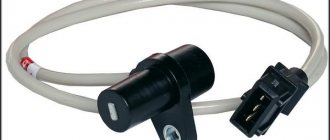
Crankshaft sensor device
In order to understand the operation and errors of the crankshaft sensor, you first need to understand the principle of its operation. It is a structure made of a steel core, wrapped with copper wire, placed in a plastic case. All wires are insulated from each other with compound resin.
Crankshaft/camshaft position sensor. Device and purpose
Video lecture about the design and purpose of the crankshaft/camshaft position sensor. Functional features and failure of the crankshaft and camshaft position sensors (DPKV and DPRV). More details
The purpose of the device is to record the passage of metal pulley teeth near the sensor. It has 60 teeth, 2 of which are missing. It is the passage of this empty gap that the sensor should record. This makes it possible to synchronize the operation of the ignition system and the power supply system in order to ensure the correct sequence of fuel supply through the injectors. This is necessary to create the optimal fuel mixture.
Before proceeding directly to the description of the operating principle of the crankshaft sensor, it is necessary to point out that there are three types in total. In particular:
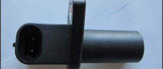
- Induction sensor . It is based on the use of a magnetized core, around which a copper wire (coil) is wound, the ends of which are brought out to record the voltage change. This type of sensor is most often installed in modern cars.
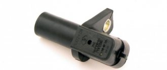
- The optical sensor operates on the basis of an LED that emits a light beam and a receiver that detects this beam on the other side. When passing the control tooth, the beam is interrupted, which is recorded by the control device. Information about the rotation speed is transmitted to the ECU.
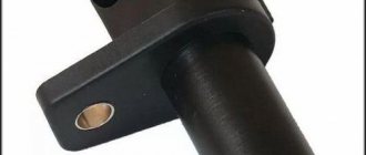
- Hall Sensor . It is based on the physical effect of the same name. So, a magnet is installed on the crankshaft, which is fixed by a sensor, in which at this moment the movement of direct current begins, which is recorded by a synchronizing disk. You can read more about this in the next article.
Next, let's move on to considering faults.
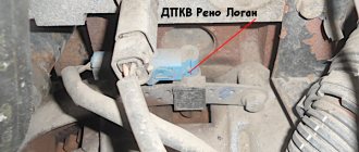
DPKV location - design features
Typically this sensor is located near the alternator belt drive pulley. On this pulley there is usually a gear ring made around the circumference, the so-called synchronization disk. It is to the rotation of this disk that the sensor responds.
It is worth noting that in order to accurately obtain data on the rotation of the crankshaft, the DCPV is located at a certain distance from the disk.
For a correctly installed device, the distance between its core and the top of any tooth should be 0.6-1.5 mm.
The location of the DKPV is not the most convenient, but it is quite possible to get to it.
Cars use several different DPKVs in design and operating principles:
- induction (one of the most common);
- sensor using the Hall effect;
- Optic.
We won’t talk about the design and operation features of each of them for now; let’s move straight to the malfunctions.
Types of sensors and operating principles
There are several varieties, but the gap is fixed using a general method. Actually, they themselves can be like this:
- Induction
- Optical
- Hall sensors.
The operation of the induction sensor is based on the phenomenon of electromagnetic induction. While the crankshaft rotates, the teeth change the magnetic field of the crankshaft sensor, resulting in induced voltage pulses.
The optical analogue has an LED instead of a magnetized core. It emits a beam, which is perceived by a receiver located on the other side. Synchronization is also carried out using special teeth (grooves). The task of the last device is to detect interruptions in the light beam, due to which a voltage pulse is formed, and it is already sent to the ECU.
Hall sensors operate according to the physical effect of the same name. There is an integrated circuit that is located right behind the magnet and the teeth just sweep past it. When the teeth pass directly under the circuit, the magnitude of the magnetic field that penetrates the Hall element changes. Due to this, a millivolt voltage signal is generated. At the same time, the integrated circuit itself produces rectangular pulses and the area where two teeth are missing will be noticeably longer. Typically, the Hall sensor is three-pin - power supply +5 Volts (+12V), ground, signal output.
Symptoms of a problem
A malfunction of this device will immediately appear. Symptoms of a faulty DCPV are:
- Inability to start the power plant;
- Decrease in car dynamics while driving;
- Floating speed in different driving modes;
- Interruptions in operation, instability of idle speed;
- Under load, detonation may occur.
It is worth noting that since this sensor is very important for the functioning of the power plant, if it malfunctions, the electronic unit will signal this by lighting up the “ Check Engine”
».
Of course, the reason for the appearance of this inscription or icon on the dashboard may also be a malfunction in some other system, however, in combination with the indicated symptoms, we can immediately assume that the DCPV is to blame for all the troubles with the car.
Symptoms
We have already become familiar with the types of crankshaft position sensors; now it is worth touching on the signs of their malfunction. Regardless of the design of the DPKV, the signs of its poor performance are always the same:
- The dynamic qualities of the car begin to decline noticeably. True, such a symptom indicates another malfunction, however, it makes sense to check the DPKV.
- The speed of the power unit changes spontaneously.
- When a car power plant is idling, the speed starts to “float” altogether.
- The occurrence of detonation due to dynamic load.
- If the electronic element fails altogether, then the engine will no longer start.
It is also worth considering that in the event of such a breakdown, the “Check Engine” emergency indicator always lights up. True, this will not specifically indicate a malfunction of the crankshaft position sensor, but it is a clear signal that some system in the engine has a malfunction.
Verification methods
Before going to a car store for a new sensor, it is still recommended to first check the one installed on the car.
This will make it much faster to determine why the car is not working well, because it is possible that the sensor is not to blame for everything, especially since some testing methods are not so complicated.
The most common are:
- checking the resistance of the sensor coil;
- comprehensive check (coil and insulation resistance, winding inductance);
- checking with an oscilloscope.
The first two checks are quite simple; you can perform them yourself if you have the necessary equipment.
The third method is the most accurate, but it can only be checked at specialized stations.
Check for VAZ 2110
Ohmmeter (multimeter).
To make it more clear, let’s look at each method of checking the crankshaft sensor using the example of several cars.
The first will be the VAZ-2110, which uses an induction type of device.
So, the engine on the “Ten” malfunctioned and there is every assumption that this happened due to the crankshaft sensor. There is a multimeter at hand that can work in ohmmeter mode.
This is quite enough to check the winding resistance.
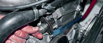
The first thing to do is to inspect the device while it is installed on the car, or rather, check for a gap between it and the synchronization disk.
It is quite possible that there is no gap there due to the fact that dirt has adhered to the sensor or disk, which led to malfunction.
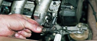
If everything is in order with the gap, we will remove the device from the car.
On the VAZ 2110 it is located on the oil pump cover.
Before doing this, it is better to mark the position of the DPKV.
The next stage is assessing the external state. The sensor body must be intact, without signs of damage, the core must be clean, the contact terminals must be free of traces of oxidation, and the wires must not be damaged.
If external contamination is visible on the DPKV, you can wash it before checking (to do this, use only pure gasoline or alcohol), and also clean the contacts with a file.
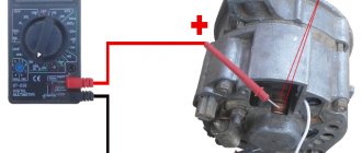
After cleaning, rinsing and drying, you can start taking measurements. To do this, switch the multimeter to ohmmeter mode and connect the probes to the sensor contacts.
When measuring, a working DPKV should show a resistance in the range of 550-570 Ohms.
For other cars, this indicator may be different, so it is better to inquire about the rated voltage of the sensor in the technical documentation of the car before taking measurements.
If the resistance value is lower or higher than the specified range, the sensor is faulty and must be replaced.
This is the easiest way to check DPKV, but it is also the most inaccurate. It can only give a partial idea of the state of the device, although this is sometimes quite sufficient.
An oscilloscope.
The most accurate method for checking is using an oscilloscope. Therefore, let’s look at how to check the sensor on a VAZ-2110 using this device.
During such a check, there is no need to remove the DCP, and all measurements are taken directly on the car.
Before carrying out the test, you need to correctly connect the oscilloscope to the machine. Typically this device has one clamp and two probes.
The clamp must be connected to the engine ground, that is, to any metal component of the motor.
One probe is installed parallel to the sensor signal output terminal. The second probe is connected to pin 5 on the scanner connector.
After connection, you should switch the device to the “Inductive Crankshaft” mode.
After this, start the engine. If it does not start, then you will need to rotate the crankshaft with the starter so that the oscilloscope takes readings.
After this, the performance of the sensor can be assessed from the resulting oscillogram. Any disturbances in its operation will affect the oscillogram image, and this will be clearly visible.
Speed lock
In addition to DPKV, sometimes there is a need to check the functionality of this device. This is usually indicated by the following signs:
- Increased fuel consumption.
- The thrust of the power unit drops noticeably.
- Speed stability in idle mode is lost.
- The speedometer does not function accurately or does not work at all.
Often the malfunction is caused by an open circuit, so it makes sense to check it for continuity. First, disconnect the chip and carefully inspect the contacts to see if there are any traces of oxidation. If necessary, clean them, after which it is advisable to lubricate them with lithol.
Typically, these elements also exist in several variations, but the most common option is a Hall sensor, as is the case with DPKV. To check the device, you can use one of three available methods.
Warning lamp
Here is also your approach:
- Prepare a test lamp.
- Turn on the ignition.
- You also hang the car wheel with a jack, as in the method above, so that nothing interferes with its rotation.
- One wire is connected to the positive terminal of the battery, the other will touch the signal contact.
- Rotate the wheel while watching the lamp.
The device will be operational if the “signal light” starts blinking. Only the verification methods listed are relevant to vehicles with a manual transmission. If there is a need to find out how to check the speed sensor (not the crankshaft) on an automatic transmission, it is better to entrust the diagnosis to professionals.
The explanation for this is simple - in such cars there are a large number of electronic components that are connected to each other directly or through the ECU.
Self-checking the device on an automatic transmission (without removing it) usually results in various troubles - the automatic transmission system gets confused, which threatens serious damage. There have been recorded cases where such amateurish behavior led to expensive repairs, or even forced sale of the vehicle. It’s better to spend money on professional diagnostics, which in any case will be cheaper than dealing with the results of personal intervention.
Check without dismantling
Here the algorithm for checking the speed sensor will be as follows:
- First, check the controller connection.
- Raise one wheel on a jack to make it easier to rotate.
- Set the multimeter to measure voltage.
- Connect the sensor contacts with the probes in a known way (as with the method above).
- All that remains is to spin the wheel and see the results - does the voltage appear and increase? This will show whether the device is working or not.
In this case, the voltage and frequency should change, which indicates the functionality of the speed sensor. A malfunction will be indicated by unchanging readings.
Using a Multimeter
The instructions on how to check the speed sensor boil down to the following:
- First, dismantle the sensor itself.
- Switch the device to voltage measurement mode.
- Perform pinout - determine which contact is responsible for what.
- The positive probe of the multimeter is connected to the contact through which pulse signals are issued. The negative probe is connected to the ground (car body, engine housing).
- The rotation of the electronic speed limiter drive determines the receipt of signals in the operating mode of the device. The faster it spins, the higher the voltage.
To facilitate the procedure, a piece of tube is placed on the axis of the device (vinyl insulation) - this makes it easier to unscrew the drive.
Comprehensive check for Opel Vectra B
Now let's take another car and use it to consider the last of the verification methods - comprehensive.
This test is much better than with a conventional multimeter, but in terms of accuracy it is not as accurate as an oscilloscope.
The problem car will now be the Opel Vectra B. We leave the symptoms the same.
The initial work is also no different from the VAZ-2110: the sensor is removed, inspected, thoroughly washed, and only after that you can start checking the condition.
But for a comprehensive check you will need more equipment:
- Multimeter;
- Megaohmmeter;
- Device for measuring inductance.
It is better to take all measurements in a heated room so that the readings are correct.
First, the coil resistance is measured, as described above. Resistance readings must be within the range specified in the technical documentation.
The next check is to measure the winding inductance, for which a device is used to measure it. A working DPKV inductance should be in the range of 200-400 mH.
The devices are pictured below.
The insulation resistance is also checked with a megohmmeter. When a voltage of 500 V is applied, the resistance value of the sensor should be no more than 20 MΩ.
Based on these measurements, it is determined whether the DPKV is working or requires replacement.
Photos of the devices are below.
Functional purpose
The sensor that records the crankshaft position has two main tasks:
- Recording the moments when the pistons pass TDC and BDC.
- Measuring the angular position of the crankshaft.
Based on the information sent by the DPKV, the ECU adjusts a number of parameters:
- Injector response time for dosed fuel supply.
- When to turn on the fuel supply.
- Moments of firing of spark plugs.
- Duration of operation of the adsorber valve, including its activation time.
- Adjusting the camshaft angle.
Modern engines have not undergone many changes from a design point of view. The key period is the transition from a carburetor system to an injection system, which has received recognition from most experts. Further development consists of improving current units and the possible use of new devices.
The complexity of power plants is only increasing every time to extract benefits and minimize damage to the environment. Based on this, the list of tasks for the “brain” of any car (that’s what the computer or ECU itself is called) is growing. But if the sensor does not transmit the necessary information, the performance of the engine will not change for the better.
Features of testing on other cars
As for other cars, for example, VAZ-2109 with an injection engine, VAZ-2112 and VAZ-2114, their check is carried out identically to the VAZ-2110 car.
It is noteworthy that for VAZs, when checking the resistance of the crankshaft sensor coil, an additional check can be carried out.
But to do this, the multimeter must be switched to voltmeter mode with a measurement limit of 200 mV.
Then connect the probes to the DPKV terminals and pass them with any metal object, for example, a screwdriver, at a short distance from the core.
If the sensor is working properly, it will react to metal, the multimeter will show voltage surges on the display. The absence of these bursts will indicate a faulty element.
As for a car like the Reno Logan, the difference from the VAZ in this car comes down to slightly different readings of the resistance of the sensor coil when measured with an ohmmeter.
A working Logan DPKV has a normal resistance of 200-270 Ohms.
For Daewoo Lanos, the coil resistance should be in the range of 500-600 Ohms.
But on the ZMZ-406 engine, installed on Volga and Gazelle cars, the normal coil resistance is in the range of 850-900 Ohms.
Checking with a wrench
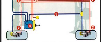
DPKV is one of the main control parts, since without it the automobile power unit will not work. It is directly connected to the electric fuel pump, so the functionality of the sensor can be checked by focusing on this device.
This is much easier to do compared to other methods, since it does not require the use of special instruments to measure electrical parameters.
Experienced automotive electrician Valery Chkalov shared a simple testing technology on his Youtube channel.
He suggests using a simple wrench as a diagnostic tool:
- This method requires preliminary preparation. To better hear the operation of the fuel pump, you must first remove the rear seat inside the car and disconnect the sensor.
- Then you should take the key and turn on the ignition.
- You need to bring the key to the metal core of the DPKV, and then tear it off.
- If the sensor is in good condition, the fuel pump will turn on. This point is easy to hear. Otherwise, this part will need to be replaced.