Working brake system of UAZ Bukhanka
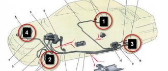
Service brake system diagram
The diagram allows you to study how the brake system of the UAZ Bukhanka works more clearly.
Fig. 1 Diagram of the working brake system of the UAZ Bukhanka: 1 – brake disc; 2 – front wheel brake bracket; 3 – outline of the front part; 4 – main brake cylinder; 5 – reservoir equipped with a brake fluid movement sensor to the emergency level; 6 – amplifier with vacuum; 7 – pusher; 8 – brake pedal; 9 – light switch when braking; 10 – rear wheel brake pads; 11 – rear wheel braking cylinder; 12 – outline of the rear part; 13 – casing of the axle axle at the rear; 14 – load spring; 15 – pressure regulator; 16 – rear cables; 17 – equalizer; 18 – central cable; 19 – parking brake lever; 20 – indicator of brake fluid movement to the emergency level; 21 – parking brake warning switch; 22 – front wheel brake pads.
Hydraulic drive of the service brake system
Since 1985, the hydraulic drive of the UAZ service brake system began to be produced with two separate branches, one of which extends to the brake mechanisms of the front wheels, and the second extends to the brake mechanisms of the rear wheels. The drive design includes:
- master brake cylinder;
- a brake pedal, which is connected to the cylinder through its piston;
- wheel cylinders of wheel brake mechanisms, both in the front and rear of the car;
- pipelines and hoses that connect all cylinders;
- control pedal and drive force amplifiers.
The lines, the inside of the master cylinder, and all wheel cylinders contain brake fluid.
When installing a brake force regulator and an anti-lock braking system modulator on a UAZ, they are also placed in the hydraulic drive structure.
The principle of operation of the UAZ brake system
When you press the pedal, the brake system operates in the following sequence:
- The master cylinder piston moves fluid into the lines and wheel cylinders;
- in the wheel cylinders, the brake fluid causes all the pistons to move, as a result of which the brake pads move closer to the drums;
- when there is no distance left between the pads and the drums, the release of fluid from the main brake cylinder will stop;
- When you press the pedal harder, the fluid pressure in the drive rises and braking of all wheels starts at the same time.
Greater force applied to the pedal results in greater pressure exerted by the master cylinder piston on the fluid, as well as greater force exerted by all the wheel cylinder pistons on the brake shoe.
This suggests that the simultaneous operation of all brakes and the regular relationship between the force on the brake pedal and the driving forces of the brakes are created thanks to the hydraulic drive system.
When the brake pedal is released, it returns to its original position due to the functioning of the return spring. In addition, due to the spring, the piston of the main brake cylinder also moves to its original position. And the tension springs of the mechanisms, in turn, move the pads away from the drums. Brake fluid from the wheel cylinders is pushed through pipelines into the master cylinder.
Advantages and disadvantages of hydraulic drive
Advantages of hydraulic drive:
- quick response provided by the impressive rigidity of the pipelines;
- high efficiency, since energy is wasted as a result of pouring low-viscosity liquid from one device to another;
- not a complex design;
- low weight and dimensions as a result of high driving pressure;
- comfortable layout of drive devices and pipelines;
- a chance to achieve the required distribution of braking forces among the vehicle axles, obtained due to the difference between the diameters of the pistons of the wheel cylinders.
Among the disadvantages of the hydraulic drive are:
- requires special brake fluid with a high boiling point and low thickening point;
- the threat of malfunctions due to depressurization as a result of liquid leakage when damaged, or malfunctions when filling the drive with air;
- a strong decrease in efficiency at low temperatures, usually below minus 30 °C.
Brake fluid
Special brake fluids are sold for use in hydraulic drives. They are produced on alcohol, glycol or oil bases. It is prohibited to mix them with each other; this can lead to a deterioration in their quality and the appearance of flakes. Brake fluids made from petroleum products may only be used in hydraulic drives whose seals and hoses are made of oil-resistant rubber. This is done in order to prevent the destruction of rubber parts.
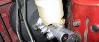
How does the GTZ function?
The unit consists of the following parts:
- metal housing with holes for supplying brake fluid, pedal rod and connecting the expansion tank;
- 2 pistons with rubber seals;
- 2 return springs;
- guide bushings;
- end plug with gasket.
An expansion tank is attached to the top of the main distributor body, where excess fluid goes through compensation holes. Inside, the element is divided into 2 cylinders with separate pistons standing on the same axis.
The blind end of the housing is closed with a threaded plug; on the other side there is a flange for attaching to the vacuum booster. The brake pedal rod is attached to the first piston. The brake circuit pipes are connected to the lower holes - separately for the front and rear wheels.
The operating principle of the master brake cylinder looks like this:
- When you press the pedal, both pistons simultaneously move forward and push fluid into the circuit tubes. Under its pressure, the wheel cylinders are activated, compressing the pads on the discs.
- Part of the liquid that does not have time to pass into the tubes flows into the expansion tank through special bypass holes.
- When the driver releases the pedal, the springs push the pistons back, returning them to their original position. Liquid from the tubes and reservoir refills the cylinders.
- To compensate for the expansion of the liquid (for example, from heating), another pair of holes is provided leading to the expansion tank.
Note. The GTZ acts in conjunction with a vacuum booster (not shown in the diagram), which helps put pressure on the pistons. This allows the system to respond faster and make the driver's actions easier.
Parking brake system of UAZ vehicles
Parking mechanism diagram
Rice. 2 Parking brake system: a – view with brake drum; b – view without brake drum; 1 – adjustment fork; 2 – lock nut; 3 – drive rod; 4 – expansion cracker; 5 – plug; 6 – drive lever; 7 – adjustment screw; 8 – block support; 9 – pusher of the expansion unit; 10 – ball body; 11 – housing of the expansion unit; 12 – brake drum; 13 – first block; 14 – tension spring of pads; 15 – cap; 16 – expansion unit ball; 17 – bolt; 18 – second block; 19 – brake shield; 20 – housing of the adjustment mechanism; 21 – rod; 22 – spring; 23 – spring cup.
Operating principle of the parking mechanism
The brake mechanism of the parking system is equipped on the transfer case and brakes the rear propeller shaft of the Bukhanka. Its design includes a support disk with two pads installed on it, connected by springs. The pads act on the brake drum, which is fixed on the centering belt of the propeller shaft flange. Attached to the top of the support disk is the housing of the expansion unit with pushers, which are attached to the top of the pads. Inside, the pushers are equipped with recesses filled with balls that are located in the rod. The housing of the adjusting element is installed at the bottom of the support disk. The recesses of the housing contain pad supports that can move due to the work of the block and the adjusting screw.
The brake mechanism drive includes a lever mounted on the support disk and an expansion element supporting the rod of the balls. The free end of the lever is attached to the fork, which in turn is attached to the rod using a lock nut. The drive rod is attached to the parking brake lever, which is installed in the driver’s cab.
In addition, on the UAZ Bukhanka, the parking brake system drive is supplemented with an extension located between the parking brake lever and the brake mechanism. This extension cord is a steel cable with elements for its fastening.
Source
Bleeding the brakes, sequence
Before pumping the brakes on your UAZ, look for a dry, flat surface. In addition, you will need an assistant, since it is difficult to perform the operation alone, but in case of urgent need it is possible.
The sequence of the process is as follows:
- We remove valve plaque;
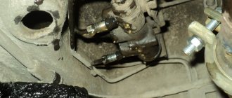
- We check whether there are any smudges or leaks in connections and pipes;
- We control the amount of working fluid in the container for compliance with the standard. If necessary, add “MAX” to the desired mark. We carry out manipulations, constantly check and bring the liquid to the required level; it is impossible for the mixture to drop to the “MIN” mark.
- We pump the foot brake lever without starting the power plant;
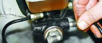
- We remove the safety cap from the cylinder bypass valve located at the rear (right) and install a light-transmitting tube, product size 400mm. We wet the unoccupied edge of the tube in a container containing half a liter of working suspension and leave the tube there;
- Press the foot lever until it stops 4-5 times;
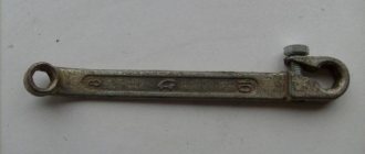
- Holding the lever with your foot, unscrew (key 11) the bleeding valve, make ½, ¾ turns;
- We control the movement of air masses in the form of bubbles from the cavity of the tube lowered into the suspension;
- When the stop lever goes all the way down, close the bleeder valve and press out the mechanism;
- We carry out the actions in the required order as long as necessary to completely remove the bubbles;
- We remove the tube and install the safety cap;
- Using the same method, we bleed the stop cylinder located at the rear (left);
- Afterwards, we perform similar actions on the pressure regulator.
The cylinders on the front wheels are pumped in the same way, the sequence of manipulations is: bottom right, top right, bottom left, top left. It is necessary to observe the pumping order. Otherwise, a situation is possible when the brakes on the UAZ loaf are not pumped. If technically there is no wear and tear, then the problem lies in a violation of the procedure.
Brake system of UAZ “Bukhanka”
The UAZ Bukhanka has always been distinguished by its reliability, cross-country ability and spaciousness, but any car requires repair . Due to its simplicity, the brainchild of the Ulyanovsk Automobile Plant can be serviced at home if you have the necessary tools and skills.
The brake system of the UAZ “Bukhanka” is one of the main parts of the car that needs to be repaired. It is a means of braking and speed control, making repairs when it breaks down a priority for safety reasons.
And, like almost all systems of this wonderful car, it can be repaired and serviced at home.
Let's start getting acquainted with this system by studying its diagram.
The braking system of the UAZ Bukhanka consists of two braking systems: a working brake system, designed to stop and regulate speed while moving, and a parking brake system, which is necessary to ensure that the car does not move while parked.
Site about SUVs UAZ, GAZ, SUV, CUV, crossovers, all-terrain vehicles
Utility vehicles UAZ-3741, UAZ-3962, UAZ-3909, UAZ-2206, UAZ-3303 are equipped with working, parking and spare brake systems. A service brake system with drum brake mechanisms on the front and rear wheels, with two separate hydraulic drive circuits to them from a two-chamber master cylinder: one to the brake mechanisms of the front wheels, the other to the brake mechanisms of the rear wheels.
The parking brake system with a drum brake mechanism located behind the transfer case and acting on the rear driveshaft has a manual mechanical drive. The spare brake system consists of each of the hydraulic drive circuits.
Installation of the service brake system of UAZ-3741, UAZ-3962, UAZ-3909, UAZ-2206, UAZ-3303, installation of front and rear brakes.
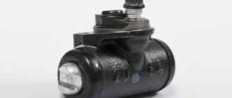
The front service brakes have two wheel cylinders, each of which acts separately on the pad. Cylinder diameter 32 mm. The rear brakes have one wheel cylinder acting on both pads. Cylinder diameter 25 mm.
Front wheel braking system.
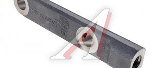
Two wheel cylinders are secured to the brake shield using support pins and nuts. The support pins have eccentrics on which brass pad support bushings are installed. By turning the support pins with eccentrics, you can move the support ends of the pads relative to the brake shield. They adjust the brakes using support pins when assembling them at the factory or when repairing brakes with replacing pads or linings.
Detailed diagram of the UAZ “Bukhanka” braking system
In the diagram, numbers represent the various components.
1) Brake disc; 2) Front wheel brake caliper; 3) Front contour; 4) Master brake cylinder; 5) Reservoir with brake fluid movement sensor; 6) Vacuum booster; 7) Pusher; Brake pedal; 9) Brake light switch; 10.22) Brake pads; 11) Rear brake cylinder; 12) Back contour; 13) Rear axle housing; 14) Load spring; 15) Pressure regulator; 16) Rear cable; 17) Equalizer; 18 Central cable; 19) Parking brake lever; 20) Brake fluid emergency level indicator; 21) Parking brake warning switch.
The braking system of the UAZ “Bukhanka” has its most common breakdowns. For example: increased braking distance, sinking brake pedal, creaking and noise when braking, leaking brake fluid.
The causes of all these problems are also known. This, as a rule, is a violation of the tightness of the system, low level of brake fluid, wear of the pads and untimely replacement of consumables.
In most cases, if the problems are not related to wear of parts, simply bleeding the braking system will help. It is performed during any depressurization of circuits, during renewal of brake fluid, as well as during any replacement of system parts (pipes, hoses, cylinders).
Do not forget that for pumping you will most likely need an assistant.
Source
Power unit
Since 2016, UAZ has been equipped with UMZ 421 engines in injection or carburetor versions. The most common engine breakdowns:
- Thermal clearances of the timing valves go away;
- the connecting rod bearings are rotated;
- the ignition system fails;
- The thermostat breaks;
- the pump does not pump;
- The engine is heating up.
Coolant replacement
After 2 years of operation or 60,000 km, the coolant in the car needs to be replaced. Replacement is carried out on a cold engine and on a level surface.
If there is crankcase protection, you will have to remove it. Open the heater tap, place the container and unscrew the cap on the radiator. We unscrew the cap of the expansion tank and the plug in the cylinder block.
You can use water to flush the system several times. Fill the antifreeze through the expansion tank, start and warm up the engine. If necessary, add fluid to the maximum mark.
Where is the charging relay located?
The charging relay protects the generator from overload and is located with it under the hood on the right side of the engine.
How to remove a radiator
The radiator on the car is initially mounted poorly - the top is on the body, and the bottom is on the frame. Mechanical stresses are created, which lead to microcracks and product leakage.
The order in which to remove the cooling system radiator is intuitive. Through the cabin and from the bottom of the machine, we unscrew the pipes and fasteners, and remove the assembly.
Copper radiators are well soldered. In aluminum devices, you can try to seal the tubes with sealants, for example, “dry welding”.
Changing the engine oil
Engine oils are used recommended by the manufacturer. Change every 10 thousand km.
If the crankcase guard is installed, it may need to be removed. Depending on the engine brand, the location of the drain plug differs.
Replacement is carried out with the car warmed up.
To avoid strong pressure from below, it is recommended to first place the container and unscrew the magnetic plug and only then open the oil filler hole.
The system should be flushed periodically before adding new oil. A cleaning agent is used for this purpose.
When the waste or flushing has drained, tighten the plug and fill in fresh oil to the upper mark of the dipstick. The car is started and the pressure is checked.
To reduce oil consumption on ZMZ engines, the valve cover of the cylinder block, the crankcase ventilation system, and the labyrinth connection of the oil deflector are modified.
How to remove the engine
The engine from the car can be lowered into the pit or removed through the passenger compartment. There is no need to remove the boxes from the car.
Before starting the procedure, it is necessary to remove the attachments, generator, fuel pump, wires, hoses and pipes, and unscrew the fastenings of the product to the body.
For safe work, it is better to use devices with a crane beam. The engine is lifted into the cabin and removed through the doors or lowered into the pit on a stand.
How to remove the starter
In order not to remove anything unnecessary, the UAZ starter is replaced from two positions - from under the car and from the cab.
Use a spanner wrench to unscrew the fasteners using short movements. We move aside the electric starter connection wires. We turn the device with the retractor relay down and remove it. The starter retractor relay is located on the side of the device body, the control relay is in the engine compartment on the left in the direction of travel. There is also a locking relay installed in the cabin.
How to connect a generator
Connection diagrams for a car generator differ depending on its modifications and engine type. Timing belts can also be different.
To replace the product, you will need an electrical circuit that matches your brand of car, or a service center specialist.
Before working with electrical wiring, turn off the onboard power. In all cars, you need to connect the battery (plus) to the generator, connect the ignition switch and a light bulb with a voltmeter on the instrument panel.
To optimize the on-board network, car owners install an additional battery through an isolation device.
Replacing the alternator belt
For the ZMZ engine, tension is performed by the power steering pump, and the procedure for replacing the belt is as follows:
- Loosen the pump fastenings to the bracket, tighten the adjustment bolt and move the assembly to the right.
- Remove the belt from all rollers.
Some models have a tension roller. The belt is removed by adjusting its position.
How to install the ignition
The ignition is adjusted by aligning the marks using the starting handle on the crankshaft and cylinder block (with an advance angle of 5º). It is necessary that the marks coincide at the end of the compression stroke of the first cylinder. This is determined by the distributor slider - it should be directed to the contact of the desired cylinder.
To set the ignition, there is a red mark on the sensor rotor, and an arrow on the stator. We relax the octane corrector and move it to the zero position. After this, by turning the distributor body, we align the marks and tighten to fix the setting.
Check the correct installation of the ignition on the UAZ by sharply pressing the accelerator while driving at a speed of 50 km/h. Detonation knocks should be no more than 3 seconds. Their absence or long duration is a sign that additional adjustment is required.
Brake system: UAZ “loaf” mechanics
UAZ 3741 or 452, called by the people “loaf”, is the most famous creation of the Ulyanovsk Automobile and is remembered as a reliable ambulance, emergency gas service, police, water utility vehicle. She has many positive qualities. It is unpretentious in maintenance, has excellent maneuverability and endurance.
But for all its advantages, like any machine, sooner or later it needs partial or major repairs. For this purpose, it is not necessary to contact service centers. The structure of a domestic car is not very complicated, and you can figure out how to repair some of its parts yourself.
UAZ brake system: device features
Replacing some parts can be delayed, but repairs to the brake system cannot be delayed. The life of passengers, drivers, pedestrians and the safety of other vehicles depend on the condition of the brakes.
The UAZ “loaf” brake system consists of:
- hydraulic drive;
- service brake;
- hand brake.
The service brake consists of two pads of the same size. Each block ends in contact with the cylinder pistons, and itself rests on a support pin. The wheel cylinders have two holes. One is for venting air while bleeding the brakes. For tightness, a valve is installed in it. The second hole is designed to drain brake fluid from the drives. Pipes connect the cylinders to the entire master cylinder system and the brake pedal.
If the front brake circuit of the UAZ “loaf” is compared with the rear brake circuit, then it is easy to understand that they are the same, with one exception. The rear brake pads operate from one cylinder, and the front ones from two. This is because the front axle requires a more efficient braking system due to the greater load during braking.
“Loaf” drum brake mechanism
The brake system of the UAZ 469, like that of the UAZ 452, is drum. The drums consist of a stamped steel disc, a cast iron rim and a reinforcement welded to the disc. On the UAZ “bukhanka” the drums are installed so that they are quite easy to reach and, if necessary, remove to install new ones. To do this, you do not have to remove the hubs, therefore, the operation of the wheel bearings will not be affected.
The drums are attached to the hubs with three screws. The location of these screws makes it possible to install new drums in their original position.
About the brakes
Since the loaf has drum brakes, it makes sense to talk about the drums themselves. In general, the design of UAZ brake drums is the same for all cars:
- cast iron rim;
- disk stamped from sheet steel;
- amplifier welded to the disk.
All these elements are combined into one structure when the rim is cast. At the same time, convenient access to the drums is provided, since they are removable. Thanks to this, cleaning and checking them will not cause serious complications, since there is no need to remove the hubs, and accordingly, the adjustment of the wheel bearings will not be disrupted.
Finally, we note that the drums are attached to the hubs by three screws. Interestingly, these screws are located unevenly, which allows you to install the drum in exactly the position in which it was when assembling this car system.
As you can see, the design of the loaf’s braking system is quite simple, but there is one important caveat:
Source: 4x4ru.com
Repair of the brake system of UAZ 452
Before undertaking repairs to the brake system, you need to determine which part of it needs replacement or restoration and what interventions the entire mechanism needs. If you hear a squeaking sound when braking, then it's time to change the brake pads. This part needs to be replaced more often than others.
The first thing to do is to determine which wheel is squeaking. Once this task is completed, you can begin dismantling the wheel. The car needs to be jacked up and the wheel with the worn pad removed. Then you need to disassemble the caliper and check the boots installed on the brakes. If they are in order, then it is not necessary to change them along with the pads.
The guides removed from the disc brackets are cleaned of rust and dirt with sandpaper. After this, they need to be lubricated and the boot installed in place. The guides may become stuck in the bracket because moisture has built up. It can be easily removed with a gas torch. Next, we begin installing a new set of pads. The place where they will be attached must first be cleaned.
The next action is to compress the cylinder of one caliper with a special tool or a hammer handle. Press firmly to install the block onto the cylinder. The entire structure is then placed into the bracket. A caliper is mounted on them in order to fix the pads as firmly as possible. It will be useful to lubricate the bolt threads with automotive oil. That's it, the brake pad replacement is complete. It will take no more than an hour for two wheels.
Replacing brake fluid
Not all car owners know that brake fluid needs to be replaced every two years when the car is used in moderate conditions. The main mistake is often that many people simply add lubricant to the required level, rather than change it completely.
Every 60 thousand kilometers, the brake fluid needs to be replaced. Car brake fluid can withstand very serious loads. During intensive driving and sudden stops, the temperature range can vary from 170 to 2000°C. It needs to be completely changed because as it moves, water gets into the liquid and dilutes it. A lower concentration negatively affects the quality of the substance. If the liquid is too diluted and boils, it can block the brakes with steam and subsequently lead to an emergency.
Nowadays, car companies have developed a special device that determines the boiling point of brake fluid. The device diagnoses the substance and displays appropriate recommendations. It can show the condition of the fluid at the moment and how necessary it is to replace it as soon as possible. The entire procedure takes no more than a minute, but this frees car owners from unnecessary hassle.
Characteristics of the UAZ ABS system
The modern “loaf” is equipped with ABS
Another important component of the braking system is ABS. Modern “loaves” also have it. The system is designed to protect the car during emergency braking from wheel blocking and skidding.
Anti-lock braking system includes:
- sensors that collect data on wheel speed;
- the main control unit, which processes information received from sensors and controls the braking process.
In order for the ABS to work fully, you need to regularly check the operation of all its parts. The sensors require the most attention. The operation of the microcontroller depends on them, which sends a signal to the valves so that they change the amount of liquid supplied to the cylinder.
Sensor failure can lead to problematic signal transmission to the main control unit. If the ABS signal is interrupted, the wheels lock when braking. If such a problem occurs, you should not fix it yourself, but rather contact a technical center.
In order for the driver to pay attention in time to the failure of the ABS sensor, the car is equipped with a self-diagnosis system. If the sensor is broken, there is no need to delay replacing it. Repairing a vacuum brake booster requires the same attitude.
UAZ “loaf” caliper
The brake caliper may also need repair. All components of the device are constantly exposed to the negative effects of water, brake fluid and salt. In order for the caliper to last longer and wear less, it must be regularly lubricated with special products. Nigrol or lithol cannot be used for these purposes. The lubricant must be heat-resistant. The operating parameter of the substance must be at least 180°C. The lubricant must not dissolve in water or brake fluid. Its main property is compatibility with plastic parts.
Lubricants can be divided into three types.
- Oxol consists of anti-seize high-temperature paste. It is used to lubricate brackets, metal surfaces of plates and pads to eliminate squeaks.
- A lubricant made from materials that work well with bolts, pins, and pistons.
- A universally used substance for lubricating all moving parts, both plastic and elastic.
Silicone high temperature caliper grease
Silicone high-temperature lubricants are the most popular. A car owner who is poorly versed in the assortment usually buys substances from the third group. The first thing to do before starting lubricant treatment is to check the dust cap and, if it is faulty, replace it with a new one. When processing, do not allow the paste to get on the anti-dust cuffs, otherwise they may swell. The lubricant is applied to the parts in a thin and even layer.