VAZ 2106 diagram
1 — side direction indicators; 2 — sidelights VAZ-2106; 3 — external headlights; 4 — internal headlights; 5 — sound signals; b — electric motor of the VAZ 2106 engine cooling system fan; 7 — sensor for switching on the electric motor of the VAZ 2106 fan; 8 — relay for turning on sound signals; 9 — relay for switching on the VAZ 2106 fan electric motor; 10 - voltage regulator; 11 — ignition coil VAZ 2106; 12 — electric motor for windshield washer; 13 — sensor of insufficient brake fluid level; 14 — ignition distributor; 15 — electric motor of the windshield wiper; 16 — spark plugs VAZ 2106; 17 — oil pressure warning lamp sensor; 18 — oil pressure indicator sensor; 19 — coolant temperature indicator sensor; 20 — engine compartment lamp; 21 — solenoid valve of the VAZ 2106 carburetor; 22 - generator; 23 — starter; 24 - battery; 25 — battery charge warning lamp relay; 26 — relay for turning on low beam headlights; 27 — relay for turning on the high beam headlights; 28 — windshield wiper relay; 29 — additional fuse block; 30 - main fuse block; 31 — reverse light switch; 32 — parking brake warning lamp switch; 33 — plug socket of a portable lamp; 34 — relay-interrupter for direction indicators and hazard warning lights; 35 — heater electric motor; 36 — brake light switch; 37 — rear window heating relay; 38 — heater motor resistor; 39 — glove box lighting lamp; 40 — external lighting switch; 41 — rear window heating switch; 42 — ignition switch VAZ 2106; 43 — low-high beam switch; 44 — direction indicator switch; 45 — horn switch; 46 — wiper switch; 47 — windshield washer switch; 48 — switch (controller) for instrument lighting; 49 — alarm switch; 50 - cigarette lighter; 51 — heater switch; 52 — brake fluid level warning lamp; 53 — switches for alarm lights of open front doors; 54 — alarm lights for open front doors; 55 — lamp switches located in the front door pillars; 56 — fuel level indicator with fuel reserve warning lamp; 57 — coolant temperature indicator; 58 — oil pressure gauge with warning lamp; 59 — tachometer; 60 — parking brake warning lamp; 61 — battery charge indicator lamp; 62 — control lamp for the carburetor air damper; 63 — speedometer; 64 — indicator lamp for external lighting; 65 — turn signal indicator lamp; 66 — control lamp for high beam headlights; 67 — relay-interrupter for the parking brake warning lamp; 68 — switch for the carburetor air damper warning lamp; 69 — clock; 70 — lamp switches located in the rear door pillars; 71 — lampshades; 72 — rear window heating element; 73 — trunk lighting lamp; 74 — sensor for level indicator and fuel reserve; 75 — rear lights; 76 — license plate lights.
Modifications
Electrical diagrams of individual branches The electrical equipment of the VAZ has undergone minor changes. Generator; 9. Upper left part of the VAZ wiring diagram This diagram allows you to examine the elements of the front part of the car. When replacing a single wire, a new one should be of the same color and size.
Lower left part of the VAZ wiring diagram This part of the diagram shows the elements and spare parts responsible for the operation of the engine and the electrical wiring system, starters, relays, etc.
Socket for portable lamp,
To troubleshoot the problem, it is worth checking all these elements and eliminating the shortcomings.
Headlight switch. While the engine is running, the sensor creates pulses that enter the transistor switch. Hazard switch;
At the time of its release it was the most prestigious and comfortable car. Auto electrics, emergency light and turn signal relay diagram for VAZ 2106
See also: Connecting a two-key era switch
Switching diagram for electric windows of the front doors
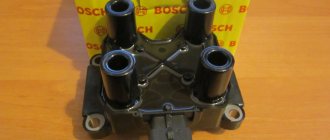
1 – main fuse block; 2 – relay for turning on electric windows; 3 – left door power window switch; 4 – right door power window switch; 5 – gear motor for the right door electric window; 6 – gear motor for electric window lifter of the left door; 7 – additional fuse block; 8 – ignition switch; A – to terminal “30” of the generator; B – to the instrument lighting switch; B – conventional numbering of plugs in the gear motor block.
Installing a new unit
Colored electrical diagram gas 2410, 24 and 21: wiring description and electrical diagram
To use fuses of the new type on the VAZ-2106, you need to install a new block instead of the old one. This is not difficult to do, just follow the tips.
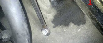
Disconnect the negative cable from the battery. Carefully unscrew the old block with a 10mm wrench
Do not allow wires to become disconnected. Pull the block down. Install wires and jumpers according to the diagram. Please note that jumpers are installed only on those wires that come from the engine compartment with voltage. Jumpers are installed between terminals: 3 and 4, 5 and 6, 7 and 8, 9 and 10, 11 and 12, 12 and 13. After this, remove the wires from the old unit one by one and install them on the new one. Check that all connections are correct. Be sure to ensure that the fuses are protecting the circuits they are supposed to.
For example, when you remove F5, the left headlight (low beam) should stop lighting. If the connection is incorrect, check the connections and jumpers
Be sure to make sure that the fuses are protecting the circuits they are supposed to. For example, when you remove F5, the left headlight (low beam) should stop lighting. If the connection is incorrect, check the connections and jumpers.
VAZ 2106 fuse box - replacement
As a rule, replacing fuses on a VAZ 2106 is carried out at the most unexpected moment. After all, they can fail at any moment. For this purpose, the driver should always have a set of new fuses with him, so that if they fail, they can be quickly replaced. But it also happens that repairing fuses alone cannot solve the problem. And then only replacing the fuse box in the VAZ 2106 helps. The old mounting block becomes unusable and thus, only replacing the fuse box in the VAZ 2106 is the only correct solution. Needless to say, after replacing the fuse box on a VAZ 2106, the driver will not be distracted for a long time by troubleshooting problems related to electrical components.
Fuses and relays VAZ 2106
- No. 1 protects the circuits of the horn, clock, brake lights, cigarette lighter, and front door open alarm lights. Fuse rating is 16A.
- No. 2 protects the circuits of the windshield washer, windshield wipers, and electric heater motor of the VAZ 2106. The fuse rating is 8A.
- No. 3 left high beam headlights, as well as the high beam indicator lamp in the speedometer (blue). Fuse rating is 8A.
- No. 4 protects the right high beam headlights. Fuse rating is 8A.
- No. 5 protects the left low-beam headlights from short circuits. Nominal 8A.
- No. 6 protects the chain of the right low beam headlights. Nominal 8A.
- No. 7 protects the trunk light circuit, instruments, license plate, cigarette lighter, left front side light and right rear side light. Nominal 8A.
- #8 protects the parking light circuit, license plate light, engine compartment light, right front side light, and left rear side light. Nominal 8A.
- No. 9 protects the tachometer circuit, rear window heating relay coils, reverse lamp, glove box lighting, battery charge warning lamp, parking brake activation, brake fluid level, carburetor choke control, oil pressure gauges, coolant temperature and fuel level, turn indicators . Nominal 8A.
- No. 10 protects the battery charging circuit, namely the generator excitation circuit and the relay regulator. Nominal 8A.
- No. 11, 12,13 in the basic configuration are in reserve and can be used for additional equipment. The denomination is selected depending on the consumer.
- No. 14 serves to protect the rear window heated element circuit, if one is installed. Nominal 16A.
- No. 15 electric engine cooling fan, if installed in the vehicle. Nominal 16A
- No. 16 protects the turn signal and hazard warning light circuits. Nominal 8A.
It is important not only to keep the contact groups clean, but also to use fuses of the ratings recommended by the manufacturer. Ignoring these requirements may result in electrical equipment failure.
Click to rate this article!
(Votes: 1 Rating: 5)
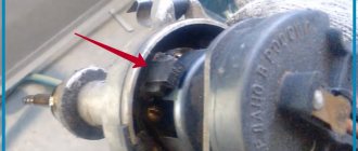
Reasons for repairing the ignition switch
Care and maintenance of a VAZ 2106 with an injection engine
The ignition switch of the “six” has 4 modes with different functionality:
- Mode “0” allows you to power only wires 30 and 30/1. Other functions are disabled.
- Mode “I” makes it possible to operate the running lights, fog lights, wiper drive, and heater motor.
- Mode “II” - in this case, the electrical wiring on the VAZ 2106 activates the turn signals, instrument panel and ignition system.
- The “III” position of the key provides power to terminals 30/1 and 30-INT. The car starter is working.
Underhood electrics of the VAZ six
Replacing the ignition switch with your own hands may be necessary for several reasons:
- Firstly, this is possible in case of loss of keys.
- Secondly, over time, the ignition switch cylinder wears out, and this affects engine starting.
- In addition, there may be problems with the contact wire group, which can lead to a short circuit.
On cars of the “classic” family, the location of the lock is below and to the left of the steering wheel. Also see the article about the restoration of domestic classics.
And it consists of the following elements and parts:
- lock body;
- contact disk;
- locking rod;
- roller and contact sleeve;
- block.
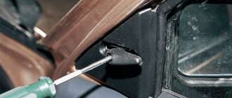
Checking the operation of the distributor
Electronic fuel level indicator
The fuel gauge sensor is one of the main control elements of a car. With its help, the motorist receives information, which is displayed on the front instrument panel, about the presence of fuel in the tank. This mechanism is based on a resistor with a moving contact (extreme resistance values are 50-300 Ohms), which changes its state during the oscillation of the float:
- If the amount of gasoline changes, the float moves and changes the resistance of the resistor;
- As soon as the fuel volume reaches the smallest figure, the contact closes, and it notifies the driver about this. Typically the signal is output to a digital fuel level sensor. The light comes on when there are 5-6 liters left in the container. fuel.
Fuel level sensor resistor
If you notice that the device displays incorrect information or does not react at all to changing the amount of gasoline, you need to dismantle it, check its condition, and if faults are found in the system, replace it with a new one.
In Soviet-made VAZ vehicles, the control device is located directly in the tank. In order to save space, it is installed together with the fuel pump. Therefore, if you need to change the FLS (fuel level sensor), you will also have to remove the fuel intake. First of all, to gain access to the device, you need to remove the rear seat and remove the special hatch.
Fuel level sensor assembly with fuel pump
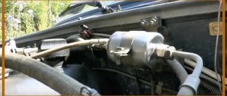
Carburetor engine
How does the wiring diagram for a carburetor engine work when starting the power unit:
- The driver turns the key in the ignition, and the system begins to supply power to this unit.
- All indicators and icons are activated on the dashboard; in this case, the equipment is powered by the battery.
- A low voltage is supplied to the coil, which is used to generate a high-voltage discharge. When the voltage passes through the module, it is converted into high voltage and supplied to the distribution node.
- By means of a high-voltage discharge, the drive of the distribution mechanism rotates the crankshaft of the Six engine. The distributor itself, in turn, closes the contacts and transmits the discharge through high-voltage wires to the spark plugs. Subsequently, this discharge is used to ignite the combustible mixture in the engine cylinders (the author of the video is the Avtoelektika HF channel).
https://youtube.com/watch?v=D3ZGfOqSHYU
Classic ignition
In accordance with the electrical diagram, a classic ignition includes the following components:
- the castle itself;
- coil;
- distributor or distribution unit;
- high-voltage cables with spark plugs.
Using a distributor, the primary winding of the module is interrupted, after which high-voltage voltage is supplied in a certain sequence to the cylinders. As stated above, a coil is used to convert low voltage to high voltage.
If nothing happens when you try to start the engine, the reasons may be:
- Damage to the wiring in the area between the module and the generator unit. In case of such a problem, it is necessary to diagnose the condition of the contacts, as well as the integrity of the electrical circuits.
- Failure of the coil itself. In this case, the functionality of the device can be checked using a spark - the cable is removed from the distributor and comes into contact with the body or engine of the car. If nothing happens when you try to start the engine, this indicates that the device needs to be replaced.
- Damage to the wiring in the area between the spark plugs and the distributor. In this case, it is necessary to diagnose the condition of the distributor cap, in particular, check the slider located inside, as well as the wires (the author of the video is the channel Alexander Amochkin Kolomna AAK).
Electronic ignition
VAZ 2106 cars were also equipped with electronic or contactless ignition (BSZ). The fundamental feature of such cars is that an electronic switch was additionally mounted between the distribution mechanism and the coil itself. In addition to the main components, the BSZ includes a switching device, as well as a sensor distributor.
With the help of the latter, control pulses are transmitted to the switching device to create a spark, after which the signals are distributed among the cylinders. The main purpose of the switching device is to convert control signals into a pulse voltage applied to the coil winding, in particular, we are talking about the primary winding. The presence of a switch helps improve discharge formation, especially if the power unit operates on a lean combustible mixture.
Instructions for diagnosing and replacing electrical wiring
The task of a car's electrical wiring is to ensure high-quality transmission of electric current to all consumers included in the electrical circuit. If any device or component does not work, before changing it, it is necessary to test the electrical wiring that connects it to the power source and other components of the electrical network.
To check the electrical network you need to prepare:
- Multimeter.
- 12V test light with two wires.
Photo gallery
1. Multimeter for checking electrical equipment
2. Indicator light for diagnostics
If you have problems with electrical appliances, you should do the following:
- Check voltage. To do this, the multimeter must be switched to voltage meter mode. One probe of the device must be connected to the mass, the role of which is played by the body. We connect the second to the power cord, having previously removed it from the device or instrument. If the tester shows the presence of voltage, then everything is in order. If there is no voltage, the source of the malfunction is located on the section of the circuit being tested.
- Short circuit. In this case, there is completely no voltage in the network. To check the mounting block, you need to remove the fuse and switch the tester into voltmeter mode. One probe must be connected to the terminals in the fuse socket. In this case, all devices included in the tested section of the network must be de-energized. If the numbers on the device jump when you move the wire, it means the wire is shorted.
- Grounding. Since VAZ cars mainly use a single-wire wiring diagram, it is necessary to check the quality of the grounding, since the body is used as a minus for electrical equipment. During operation, metal parts of the body oxidize, become rusty, and their fastening becomes loose. In this case, electrical contact is lost and electrical appliances operate intermittently.
Grounding testing is carried out according to the following algorithm:
- Remove the negative terminal from the battery. Connect one multimeter probe to the car body.
- The second probe is connected to the connection or ground point being tested.
- When values appear on the device, they should be checked against the recommended factory parameters. If the values match, then the grounding is OK.
Checking circuit integrity. This test is necessary to find open circuits.
The verification procedure is as follows:
- The section of the circuit being tested is de-energized: the negative terminal on the battery is disconnected or the corresponding fuse is removed.
- To test the circuit, the multimeter wires are connected to its ends, and one of the probes is connected to ground.
- If numbers appear on the display, this indicates the integrity of the circuit. If nothing appears on the screen, then there is a break in the circuit.
When replacing electrical wiring, use standard wiring or homemade wiring using elements from the standard one. You can use wiring from another car if it meets its specifications.
To replace the wiring, you need to disassemble the front part of the car. If the length of the wires is not enough, they should be increased. All connections must be well insulated. It is better to connect the wires by soldering. It is not advisable to twist the ends of the wires.
Advantages of contactless systems
For an ignorant car enthusiast, the main argument in favor of BSZ is the fact that at the moment not a single manufacturer produces cars with a contact-cam spark generation system. Foreign brands abandoned it in the distant 80s of the last century, and in the Russian Federation mechanical ignition lasted until the 90s. The reasons for the refusal are quite clear:
- sparks constantly flashed across the contacts, causing them to burn and require frequent cleaning;
- the contact group wore out quite quickly, on average it was enough for 15-20 thousand kilometers, after which the element had to be replaced;
- the wear of the bearing on which the contacts were located made itself felt, which caused unstable operation of the power unit;
- the springs of the balance weights were stretched.
Non-contact ignition produces a powerful spark, which makes fuel burn better
All of the listed malfunctions appeared one by one, haunting the owner of the “classic” Zhiguli. Due to an imperfect design, the spark power of the spark plugs was constantly decreasing, engine performance was deteriorating, and fuel consumption was increasing. New BSZ systems are free of such disadvantages; they are characterized by durability and stable sparking. The spark power also increased, since the output pulse voltage increased from 16-18 kV to 24 kV, which contributes to better ignition of the fuel.
How to prevent wiring malfunctions?
What you need to consider to avoid problems with electrical circuits:
- The procedure for replacing wires must be performed with electrical appliances and the battery turned off.
- Disconnecting and connecting battery contacts is only allowed with the ignition off.
- When checking the wiring, a short circuit must not be allowed; this can lead to damage to electrical appliances.
- Do not use metal tools to remove safety devices.
- Do not disconnect the battery while the engine is running. As a result, the car owner may face the problem of failure of the voltage regulator and other components of the circuit.
- If the functionality of the diode bridge of a generator set is being checked, the use of a megohmmeter powered from a network with a voltage of more than 12 volts is not allowed.
- When welding the body, the battery and generator must be disconnected. It is also necessary to disconnect the ECU, if present, from the power supply.
- It is not allowed to carry out repairs or replace wiring when the engine is turned off.
- Periodically recharge the battery and clean its terminals.
Loading …
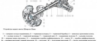
General information about the brand
Domestic cars of the 2106 brand were manufactured for the purpose of operating on roads equipped with improved surfaces, regardless of weather conditions. The cars are equipped with a four-door all-metal sedan body.
Cars are equipped with carburetor gasoline engines, four-speed or five-speed gearboxes. There is an independent spring front suspension; The rear suspension is dependent spring. The car's braking system is dual-circuit; there are disc brakes on the front wheels.
The rear ones are equipped with drums. Cars of the VAZ 2106 family were equipped with radial tubeless tires. The steering column has an anti-theft device that is built into the ignition switch.
The modification range of the VAZ 2106 family includes:
- VAZ 2106, 21065-00 - equipped with a model 2106 engine;
- 21061, 21065-01 – equipped with a model 2103 motor;
- 21063 – there was an engine from 21011.
- Car brand 21065 is the luxury version of this family. It has the following differences from the 2106 model: it is equipped with a five-speed gearbox and a final drive with a gear ratio of 3.9. Some cars were equipped with a Solex-type carburetor and a contactless ignition system. The car's electrical equipment is complemented by an electrically heated rear window, halogen headlights and a rear fog lamp. The body has been modified: the upholstery and seat headrests have been updated; The car is supplemented with bumpers of the 2105 model. Spare parts for the presented vehicles are available everywhere. In addition, the electric power steering is a kind of “novelty”, so to speak, the trends of the 21st century are making themselves felt. Thanks to this, car maintenance and repairs are not a big problem.
Methods for checking temperature sensors
If the driver wants to make sure that the cause of problems with the car is the antifreeze sensor, then he will have to carry out a simple checking procedure. But before you start, you need to make sure the integrity of the car wiring. As mentioned above, for the sensor to work normally, it must be continuously supplied with a voltage of 5 volts. To make sure that the supplied voltage does not deviate from this value, you should start the car, and then remove the wires from the sensor and connect them to a multimeter. If the device clearly shows 5 volts, then there are no problems with the wiring and you can begin to examine the sensor itself. There are two verification methods. Let's list them.
Hot water test
The sequence of actions in this option is simple.
- The sensor is placed in a pan of cold water. An electronic thermometer is also placed there (it is much more convenient than a regular one, because the measured temperatures will be quite high).
| Temperature, °C | Resistance, Ohm |
| +5 | 7280 |
| +10 | 5670 |
| +15 | 4450 |
| +20 | 3520 |
| +25 | 2796 |
| +30 | 2238 |
| +40 | 1459 |
| +45 | 1188 |
| +50 | 973 |
| +60 | 667 |
| +70 | 467 |
| +80 | 332 |
| +90 | 241 |
| +100 | 177 |
This method of checking the sensor is simpler than the previous one, but less accurate. It is based on the fact that the temperature of boiling water reaches one hundred degrees and does not rise higher. Therefore, this temperature can be used as a reference point and find out what the sensor resistance will be at one hundred degrees. The sensor is connected to a multimeter switched to resistance measurement mode, and then immersed in boiling water. However, you should not expect the multimeter to show a resistance of 177 ohms, which corresponds to a temperature of one hundred degrees. The fact is that the temperature of water constantly decreases during the boiling process and averages 94–96 °C. Therefore, the resistance on the multimeter will vary from 195 to 210 ohms. And if the numbers produced by the multimeter differ from the above by more than 10%, the sensor is faulty and it’s time to change it.