Car theft is an everyday occurrence, which is why car alarm systems are purchased when purchasing a car in 100% of cases.
The Tomahawk anti-theft alarm system is a professional security system that uses modern advances and technologies. Experienced car owners claim that this is one of the best car protection systems today.
Tomahawk system capabilities
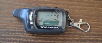
The company produces several versions of indicator key fobs, but the basic model is TZ-9010. Main features:
- remote start of the car engine for any period of time. This function is programmed in advance. This allows, for example, to warm up the car in advance during cold periods;
- auto system self-diagnosis;
- function to call the owner when any sensors are triggered;
- the presence of an anti-scanner and anti-grabber to protect against software hacking.
In more advanced versions, the remote control allows you to control the power sensor and perform remote (at a distance) autostart (if there is a built-in immobilizer). Also in advanced models, the range of the key fob is increased to 1.2 kilometers. It is possible to open the trunk of a car from a distance, as well as block the engine.
The latest version is capable of searching for the owner's lost car within range and has an indication of impacts on the car.
Instructions for setting up the key fob
Only a remote control with two-way communication mode and a display can be configured. Key fobs with display for systems 9010, 9020 and 9030, as well as 7010 are unified.
The remote control is switched to the vibration motor information mode by simultaneously pressing the KN02 and KN05 buttons. Switching back is done in a similar way. There is no buzzer volume adjustment on the remote control.
Setting the clock, alarm and timer
To set the clock in the key fob you need to:
- Press and hold the KN05 button to turn on the setting mode.
- Set the required hour value using the KN03 (forward) and KN04 (backward) keys. By holding the buttons, the value is quickly set.
- Press KH05 once and adjust the minutes. The setting is done by analogy with a clock.
Setting the alarm is done after setting the clock:
- After the minutes have been set, press KH05 twice. It is possible to quickly launch the alarm programming procedure by simultaneously pressing KN03 and KN05.
- Set the clock value for wake-up time.
- Press KN05 three times.
- Adjust the minute value.
- Press KN05 four times and enter the submenu for turning the alarm on and off. Select a value using the KN03 (On) and KN04 (Off) buttons.
Setting the timer:
- After turning the alarm on or off, you need to press KN05 five times.
- Set the hour value.
- Press KH05 six times and set the number of minutes.
- Press KH05 seven times and activate or deactivate the start of the timer.
It is possible to set the timer in stages by using KN04 and KN05 together. The KN04 button is held and the number of presses with the KN05 key is changed.
| Number of clicks KH5 | Timer value, minutes |
| 1 | 10 |
| 2 | 20 |
| 3 | 30 |
| 4 | 60 |
| 5 | 90 |
| 6 | 120 |
Key fob batteries and their replacement
The reason for replacing the battery in key fobs is to reduce the range of the signal. On the main communicator, the battery status can be checked by the icon. If there is not a single charge section left on the icon or only one is lit, then the residual charge of the battery is low and needs to be replaced. The battery life depends on the intensity of use of the key fob and the quality of the battery itself. On average, an element lasts 4-6 months.
Main keychain
For replacement, it is recommended to use alkaline batteries with a voltage of 1.5 V and size AAA. Nickel-metal hydride batteries with similar characteristics can be used.
Replacement Guide:
- Move the cover latch located on the back of the key fob to the side.
- Open the compartment cover by sliding it along the guide grooves.
- Remove the old element from the socket.
- Press the KN03 button. Pressing is required to discharge the capacitors installed on the control board.
- Install a fresh battery into the compartment, observing the polarity. The battery installation diagram is printed on the cover or at the bottom of the compartment (location depends on the year of manufacture of the key fob).
- Place the cover in place and snap the latch.
- Press down the KN03 button. The status of the key fob will be polled and the icons will turn on on the screen.
To extend the battery life, you can use the energy saving mode. When it is turned on, the communicator receiver is automatically deactivated two minutes after pressing the disarm key. The corresponding warning indicator turns on on the remote control display. The mode is activated by pressing the KN01 and KN05 keys together until the icon turns on.
Additional keychain
According to the factory manual, the additional key fob uses a 3 V lithium battery.
To replace it you need:
- Unscrew the self-tapping screw securing the housing halves.
- Carefully pry up the halves and disconnect the latches located around the perimeter.
- Remove the old element and install the new one, observing the polarity.
- Snap the housing halves into place and tighten with a screw.
- Check the operation of the remote control.
The additional remote control is used less frequently and, due to its one-way mode, consumes less current during operation. The battery life is up to two to three years.
Starting the engine from a distance
Press button “2” once. The dimensions should blink three times, and the “16” icon will appear on the screen. The engine will run as long as pre-programmed, and then turn off. If you need to urgently increase the engine operating time, you can simultaneously press buttons “1” + “2”. The time will increase by 5 minutes.
However, to start the engine from a distance, a number of conditions must be met:
- the ignition must be turned off;
- the hood must be closed;
- the car must be put on the handbrake;
- The gearshift lever must be in neutral position.
If at least one condition is not met, the engine will not start and the siren will beep 4 times.
Buttons and icons
Description of buttons and functions performed:
- KN01, available on the main and additional remote control, indicated by a closed lock icon;
- KN02, available on both types of remote controls, has an icon in the form of a key;
- KN03, used on all remote controls, pictogram in the form of a silhouette of a car with an open trunk lid;
- KN04, present on the main and additional remote control, has a symbol in the form of a speaker crossed out by two lines;
- KN05, used only on the main keychain, indicated by the letter F in a circle.
Main remote control buttons
Additional remote control buttons
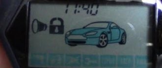
The screen has a number of icons informing the user about the alarm status and events that have occurred:
- The parking brake is applied (signal from the limit switch installed under the lever).
- The system is in security mode, the siren is active.
- The system operates in security mode without sound signals (the siren is disabled).
- Locking is enabled.
- Indicates that the locks are unlocked.
- Silent mode of operation of the key fob with signals sent by a vibration motor.
- Service operating mode (during setup or other situations).
- Battery charge level (three stages).
- The body door is open (one or more, the signal comes from the limit switches in the locks).
- The power unit is started.
- The trunk lid is open (information from the limit switch).
- An additional field used to display the temperature measurement scale. Indication in degrees Celsius or Fahrenheit is possible.
- Indicator field for clock, alarm time, service messages. Consists of four fields for displaying numbers, the fields are separated in pairs by the “:” symbol. On the left there are two modes - AM (before lunch) and PM (after lunch). The clock display is carried out in conjunction with these modes.
- The alarm is active.
- Timer is active.
- Repeated autostart every 24 hours.
- Low power consumption mode (to increase battery life).
- The car is in the reception area.
- Identification of the active two-way communication channel.
- Driver call signal.
- Autostart based on air temperature is enabled.
- Triggering of the shock sensor in the warning sensitivity zone (weak shock).
- Alarm based on data from the shock sensor (strong shock, normal sensitivity zone triggered).
- Deactivation of the first (warning) sensitivity zone.
- Complete disabling of the shock sensor.
- Anti-robbery mode activated.
- The hood lock is open (signal from the limit switch).
- External light signaling works (turn signal lamps or parking lights, depending on the connection).
Designation of icons on the display
Heating at a given temperature
The system has a temperature sensor (located under the hood). It is he who will be responsible for the temperature level when warming up the car.
You can turn on the heating by simultaneously pressing buttons “2” and “3”. When turned on, the lights will blink once and the siren will sound once. When warming up, the screen will display 1 2 temp start.
Pressing this button combination again will turn off the heating.
Key fob programming
At the user's request, additional control panels can be used, which need to be programmed and stored in the memory of the base unit.
The “signaling” model Tomahawk 9010 can be controlled by four key fobs. When you try to record the fifth one, the first remote control is deleted from memory.
Programming procedure:
- Disable security, insert the key into the ignition and turn it to the “On” position (the starter does not need to be turned on).
- Press the service button and hold it until the standard siren sounds four short signals. Signaling indicates the activation of the key fob programming mode.
- Release the key.
- Press and hold the KN03 and KN04 keys simultaneously on the new remote control. The recording of the remote control will be confirmed by a short beep from the siren. Depending on the number of the key fob in the memory, a different number of sound signals (from one to four) is given.
- If there is no signal from the remote control within six seconds, the system exits programming automatically. The user should remember that key fobs that are not reprogrammed will be deleted from memory. That is, when recording one new remote control, you need to enter all existing ones into memory.
Main functions of the key fob
Regardless of the alarm model, a button with the corresponding “lock closed”/“lock open” icon is used to arm and disarm it. The method of opening the trunk is also clear from the icon on the third button.
On Tomahawk 8.1 and 10.1 there is no trunk opening icon on the main key fob buttons. To do this, use a long press on the “+” button.
To turn off the shock sensor (for example, if it triggers repeatedly at night), press:
- Tomahawk 10.1 has both “removal/arrangement” and “crossed out speaker”
- For Tomahawk 8.1, G-9000, Z-5 – press “arm” twice
Model identification for Tomahawk one-way alarms
The old Tomahawk types CL-350 and CL-300 used the same key fobs, both came with the same ones - like most simple one-way alarms.
To accurately determine the brand and model of the Tomahawk alarm, you will still have to get to the central unit, if this is so important: the CL-500 has a built-in blocking relay, while the CL-350 has an external one connected. This is the difference between the two models.
Developing this line, Tomahawk releases the CL-550, which is still on sale. Here the keychains are also the same, the design has become much more aggressive.
The latest car alarm in the one-way line is CL-700. Misunderstandings often arise here - after all, both key fobs (also identical) have a liquid crystal display!
People who have bought cars with installed systems immediately have a question: why doesn’t the feedback work? It shouldn’t - the information on the screen changes every time the corresponding button is pressed, but the key fob will not warn you about an alarm being triggered.
Note, Daily (1,2,4,12 hour) autostart, Remote status polling
Page 10
- Image
- Text
(see programming table).
To disable this function, press the and buttons.
The parking lights will flash 2 times, the system will emit 2 “CHIRPS”,
confirming that the function is disabled. The ^ icon will disappear on the display of the key fob pager and a melody will sound.
Note:
Automatic engine warming up at a given temperature
performed no more than 6 times in 2 hours.
The temperature for automatic engine warm-up can be
set to -5°С, -10°С, -20°С, -30°С (see programming table).
15. Daily (1,2,4,12-hour) autostart
To activate this function, you must simultaneously press and
hold down the and buttons. The siren will emit 1 “CHIRP” to confirm
activation of the function. The icon ^ will appear on the display of the key fob pager
a melody will sound.
After activating this function, starting from the next day, the system
will automatically start the engine daily at the time this function has been activated.
To disable the daily autorun function, you must
press buttons
and Shch. The parking lights will flash 2 times, the system
will emit 2 “CHIRPS” confirming that the function is disabled. On display
key fob pager, the ^ icon will disappear and a melody will sound.
To activate 1, 2, 4, 12 hour start you need
activate the daily autorun function, and then within 5 seconds. After activating it, press the corresponding button on the key fob:
in - for hourly start,
M) - to start the engine at intervals of 2 hours,
16 - to start the engine at intervals of 4 hours,
- to start the engine at intervals of 12 hours.
16. Remote status polling
To perform remote polling of the vehicle status, you must
press the button
||B
. The parking lights will flash 3 times to confirm
transmitting data to the key fob pager receiver: internal temperatures
interior, security status, etc.
TOMAHAWK TW-901 o
10
Comments
Hello, I have a problem with the signaling, not a single button on the remote control works and the turn signals flash three times with a pause
Alexander 02/24/2021 08:19 GMT
Why do you need valet mode?
Bair 04/05/2021 21:16 GMT
I can't arm the alarm sound
Bakhytzhan 04/17/2021 19:06 GMT
Select → I found instructions for my car alarm here! #manualza
- Click →
From the instructions for a Chinese fire extinguisher: - Do not spray near an open fire!
Manualza!manualza.ru
Still not with us?
How to install?
Installation of the “signaling” in a garage is done as follows:
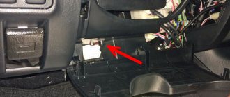
- The control module is installed inside the car. It is necessary to choose the most hidden location for installation. Some installers place the module under the dash near the hood release lever. But a more reliable place is behind the glove compartment or control panel, if there is free space there. For installation, you will need to dismantle the dashboard and remove part of the interior trim. The central module must be securely fixed using self-tapping screws so that it does not vibrate while driving.
- The signal transceiver must be installed as high as possible in the car interior, for example, near the windshield. This way the transmission of impulses will be most effective. There should be no metal objects or wire harnesses near the antenna.
- The siren with speaker is installed in a hidden place under the hood. If a stand-alone device is used, it is necessary to provide access to the hole for installing the service key in advance. The siren must be installed so that its horn is directed downward, this will eliminate the possibility of moisture ingress. At the same stage, you should think about how the wires will be connected. It is advisable to choose the location for their connection in the cabin to prevent possible oxidation of the contacts in the future.
- The luggage compartment and hood limit switches are installed so that they are not exposed to moisture. When the trunk and hood are locked, an attacker should not have access to the limit switches.
- The shock controller is installed inside the car. It is best to place it in the central part of the body so that the sensor records the physical impact on the car from all sides. The device is secured using self-tapping screws or glue. You can install the sensor in the partition separating the passenger compartment and the engine compartment.
- If you plan to use the option of remote start of the internal combustion engine, then you need to install a temperature controller in advance. The device is installed in the cooling system line. The controller must be placed away from the intake manifold.
- All high-current wires intended for connecting emergency signals, power, central locking and other elements should be protected using safety devices.
1. Control module connection diagram
2. Connection diagram of the plug for remote starting of the internal combustion engine
3. Diagram of connecting the system to the lock
4. Connection diagram of the contacts of the sensitivity controller and the Valet key
Connecting the plug
To enable the remote engine start option, you must correctly connect the six-pin plug:
- The yellow-black contact must be connected to the starter device. The 12 Volt output pulse is connected to the solenoid relay. The contact should be connected to an electrical circuit in which voltage appears when the key is turned to the starter position. This output is considered the main one, since it ensures the start of the power unit. The contact is connected in the area after the motor blocking relay.
- The blue output is for activating auxiliary equipment. It must be connected to the lock contact, where there is voltage when the ACC mode is activated.
- The thinner red contact represents the power supply circuit for the “signal”. It must be directly connected to the battery, the circuit is protected by a 10 Amp fuse.
- The thick red output represents the remote start circuit. It connects directly to the battery through a 30 Amp fuse device.
- The yellow contact is intended for connection to the ignition switch. It must be connected to an electrical circuit where there is twelve-volt voltage when the key is turned to the ignition on position. In this case, no current should be lost in this section of the wiring when the key is switched to starter mode.
- The green contact is connected to a similar section of the circuit as the output described above.