Everyone knows that in a car, a mechanical differential with manual or automatic gear shifting is used to connect the power unit with the chassis and change the traction force on the wheels.
A gearbox is a complex transmission mechanism for mobile vehicles, designed to expand the range of rotation speed and torque transmitted from the engine, the possibility of short-term or long-term disconnection of the internal combustion engine from the chassis, and regulation of the direction of movement of the vehicle.
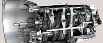
Diagram of a 5-speed gear shift mechanism for VAZ-2123
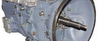
At the factory, modern Niva cars are equipped with a five-speed gearbox , made according to the three-shaft design.
Gearbox design:
The main elements of the box body are the clutch dome, the gearbox housing itself and the rear cover. The production of frame parts is carried out at the plant from a modern aluminum alloy with chemical additives.
Heat removal from heated rubbing parts is realized by manufacturing a multi-fin structure on the surface of the crankcase and also to protect the speed selection unit from overheating and exceeding excess pressure, a breather is present in the design.
The tightness of body connections is ensured through the use of pressed shaped gaskets. In case of repair of the gear selector assembly, it is also possible to use a liquid gasket former. The lower part of the gearbox housing is covered with a stamped steel protection with a gasket.
In a modern design, the gearbox housing and synchronizer clutches are reliable and adapted to operating conditions on Russian roads.
The factory crankcase protection on the Chevrolet Niva copes with its function quite well. For safe travel on rural roads and off-road, you can consider installing additional combined protection for the gearbox and transfer case. There are many different options and designs offered on the Internet, where you can choose the option you like, both in price and in terms of configuration and quality of metal.
Features of the gearbox on Niva
VAZ 21213 car with an engine capacity of 1.7 liters. can develop power up to 79 horsepower. Fuel consumption averages 10 liters per 100 km. As is typical for gasoline engines, there is a central injection system. Such vehicles should be fueled with AI-95 gasoline.
The Niva gearbox (VAZ 21213) is a five-speed manual transmission. The Niva's transmission has permanent all-wheel drive. It should be noted that there is a reliable gearshift lever extension on the Niva. Thanks to it, speed modes can be changed quickly. The existing camshaft drive is chain driven. The crankshaft includes several connecting rods and main journals. The crankshaft is distinguished by its durability and is made of cast iron. The timing mechanism is covered with a cover. There is an oil filler neck here.
Niva checkpoint diagram
A transfer case is installed on the Niva 2121. Its peculiarity is that it has both high and low gears. It is important to use an increased one if you need to save on fuel consumption. In the event that movement occurs over rough terrain, a lower gear helps out. However, in this case, fuel consumption will increase.
Article on the topic: What types of automatic transmissions are there?
Transfer case diagram
The transfer case allows you to disable one of the drive axles if necessary. The transfer case includes shafts, a differential, and a gearshift clutch. The main failures are expressed in the fact that over time its main components wear out, as a result of which the box may overheat and problems with switching on the bridge may appear. Repair of the VAZ 21213 gearbox is required if characteristic vibration from this unit begins to be observed.
Thus, the popularity of the car is explained by the fact that it has an all-wheel drive system. The speed box diagram shows that it includes a large number of components that interact with each other, ensuring excellent performance of the car.
Rear and front gear ratios of Chevy Niva
Gear values for Chevrolet Niva manual transmission from 2002 to present:
- I – 3.67;
- II – 2.10;
- III – 1.36;
- IV – 1.00;
- V – 0.82;
- 3rd gear transmission – 3.53.
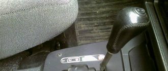
To engage the gearbox, you need to move the gearshift lever all the way to the right and push it down with a little force, pressing the gearshift knob in the direction of the rear seats of the car.
The VAZ-2123 gearbox does not have a separate synchronizer for the reverse gear. Accidental engagement of reverse gear is eliminated due to the use of a curved locking stop in the form of a bracket in the design.
content .. 41 42 48 ..Important! The reverse speed of the Niva Chevrolet gearbox, like any car, must be turned on when the car is completely stopped.
VAZ-21213 (Niva). Disassembly and assembly of the gearbox
GENERAL INFORMATION Gear shift drive 1 – fork for selecting 3rd and 4th gears; 2 – fork rod for 1st and 2nd gears; 3 – fork rod for 3rd and 4th gears; 4 – shift fork for 1st and 2nd gears; 5 – fork rod for 5th gear and reverse gear; 6 – blocking crackers; 7 – clamp cover; 8 – clamp spring; 9 – ball of clamps; 10 – fork for 5th gear and reverse gear; 11 – head of the fork rod for 5th gear and reverse gear;
| 12 – gear block of 5th gear and reverse gear; 13 – axis of the reverse intermediate gear; 14 – reverse intermediate gear; 15 – guide plate washer; 16 – guide plate; 17 – gear shift lever housing; 18 – ball joint; 19 – spherical washer; 20 – spring; 21 – thrust washer; 22 – retaining ring |
Main shaft parts
| 1 – retaining ring; 2 – spring washer; 3 – bearing; 4 – input shaft; | 5 – synchronizer spring; 6 – synchronizer blocking ring; 7 – retaining ring; 8 – bearing |
Secondary shaft parts
| 1 – retaining ring; 2 – spring washer; 3 – synchronizer hub; 4 – synchronizer clutch; 5 – blocking ring; 6 – synchronizer spring; 7 – washer; 8 – third gear gear; 9 – secondary shaft; 10 – 2nd gear gear; 11 – 1st gear gear; 12 – gear bushing; 13 – bearing; 14 – key; | 15 – reverse gear; 16 – spring washer; 17 – fifth gear gear; 18 – oil deflector washer; 19 – spacer sleeve; 20 – rear bearing of the secondary shaft; 21 – oil seal; 22 – elastic coupling flange; 23 – lock washer; 24 – nut; 25 – seal spring; 26 – seal; 27 – centering ring |
Parts of the lever and gear selection mechanism
| 1 – gear shift lever; 2 – gasket; 3 – ball joint; 4 – spherical washer; 5 – spring; 6 – ring; 7 – retaining ring; 8 – flange; 9 – cuff; 10 – protective cover; 11 – handle; 12 – lever rod; | 13 – thrust pad; 14 – elastic bushing; 15 – spacer sleeve; 16 – locking sleeve; 17 – gear shift lever housing; 18 – sealing ring; 19 – guide plate washer; 20 – guide bar; 21 – spring; 22 – guide plate; 23 – reverse locking plate |
Gear selection mechanism
| 1 – guide plate washer; 2 – guide plate; 3 – gear shift lever housing; 4 – ball joint; 5 – spherical washer; 6 – spring; 7, 8 – retaining rings; 9 – gear shift lever; | 10 – protective cover; 11 – flange; 12 – reverse locking plate; 13 – spring; 14 – guide bar; 15 – sealing ring; A – risk |
Disassembly PERFORMANCE
1. Wash the gearbox and install it on the stand. Drain the oil and remove the bottom cover with gasket. 2. Remove the clutch release fork, and from the guide sleeve of the front cover of the gearbox, remove the clutch assembly with bearing and connecting spring.
| 3. Remove the clutch housing with the gasket and the front cover of the gearbox along with the oil seal and spring washer (red arrows indicate the nuts securing the clutch housing to the gearbox, white arrow indicates the hole in the front cover for releasing oil from the gearbox housing) to prevent oiling clutch discs. |
4. Unscrew the reverse light switch, being careful not to deform its housing. 5. Remove the bolt securing the shift fork for 3rd and 4th gears. Install clamp 41.7816.4068 on the input shaft or engage two gears at the same time. This will prevent the primary, secondary and intermediate shafts from turning and will allow subsequent disassembly operations to be performed.
| 6. Remove the snap ring from the end of the transmission output shaft. |
| 7. Having straightened the lock washer, unscrew the nut a few turns to move the centering ring of the elastic coupling, and tighten the nut again. Using a pusher A.40006/1 with a puller A.40005/4, remove the centering ring of the elastic coupling of the cardan shaft from the end of the secondary shaft. |
| 8. Remove the seal of the centering ring of the elastic coupling with the spring from the end of the secondary shaft, unscrew the nut 4 and remove the flange of the elastic coupling 1 using a puller A.40005/3/9B/9C 2 (3 – stripper bar). |
| 9. Before removing the rear cover, set the gear shift lever to the neutral position, unscrew the gear selector mounting nuts and remove the gear shift lever assembly with the selector mechanism. One of the cover fastening nuts is unscrewed from inside the gearbox housing with the bottom cover removed. When removing the rear cover, it must be moved not only backwards, but also turned to prevent it from touching the reverse and fifth gear gear block. |
10. Remove the bearing spacer 44 from the secondary shaft of the inner ring of the rear bearing 43 (see Fig. Gearbox).
| 11. Loosen the bolts securing the cover 5, unscrew the bolts 2 and 4 securing the gear block and the fifth gear and reverse fork. (1 – reverse intermediate gear, 3 – fork rod) |
12. Remove the oil deflector washer 45 (see Fig. Gearbox).
| 13. Remove bushing 1 of the fifth gear. |
| 14. Remove rod 1 from fork 2. At the same time, distance sleeve 3 is removed from the rod. Then remove gear block 4 from the intermediate shaft spline. |
| 15. At the same time remove the reverse intermediate gear 1 from the axle, gear 3 assembled with clutch 2 and fork 4 from the secondary shaft |
| 16. Using shaped mandrels (such as screwdrivers), remove hub 4 of the fifth gear synchronizer and driven gear 2 from the key (1 – intermediate shaft of the 5th gear synchronizer, 3 – axis of the reverse intermediate gear; 5 – secondary shaft, 6 – shift fork rod I and II gears, 7 – shift fork rod III and IV). |
17. Using shaped mandrels (such as screwdrivers) and rod drifts, remove the front and rear intermediate shaft bearings from the gearbox housing. On the inner rings of a double-row bearing, place marks according to which these rings should be installed in their original places in the outer ring of the bearing.
| 18. Remove the intermediate shaft from the gearbox housing by tilting it. |
19. Remove the shift fork rods of 1st, 2nd, 3rd and 4th gears from the gearbox housing one by one, having previously unscrewed the fork mounting bolts. When removing the rods, simultaneously remove three locking blocks 6 (see Fig. Gear shift drive).
| 20. Remove the secondary shaft intermediate bearing retaining plate. Unscrew the nut securing the reverse intermediate gear axis and remove it (the arrow shows the direction of the impact stroke of the screwdriver cage when struck with a hammer). |
| 21. Using mandrels (such as screwdrivers), remove the input shaft along with the bearing and synchronizer ring and remove the needle bearing from the front end of the secondary shaft. |
| 22. Knock the secondary shaft out of the intermediate bearing, remove the intermediate bearing and, tilting it, remove the secondary shaft assembly with gears, clutches and synchronizer rings from the crankcase. Remove the synchronizer clutch for 3rd and 4th gears from the shaft. |
23. Disassemble the input shaft (see Fig. Parts of the input shaft): – remove the locking ring 7, blocking ring 6 and synchronizer spring 5; – install the shaft on the press and, using a mandrel 41.7816.4069, compress the spring washer 2, remove the retaining ring 1, and then the spring washer and bearing 3. 24. Disassemble the secondary shaft (see Fig. Parts of the secondary shaft). Remove the gear from the rear side of the shaft 11 of the first gear with a sleeve 12, a hub 3 with a sliding clutch 4 for switching 1st and 2nd gears, a gear 10 of the second gear together with a synchronizer blocking ring 5.
| 25. Install the secondary shaft with a mandrel 41.7816.4069 (1) on a press, place support half-rings 3 under the 3rd gear gear and, pressing the mandrel on the spring washer, remove the locking ring 2, then the spring washer 4, the hub of the sliding clutch for shifting 3rd and 4th gears and 3rd gear gear. If necessary, disassemble the lever and gear selection mechanism. |
26. Remove the protective cover 10, locking and thrust rings 6 and 7, spring 5 and spherical washer 4 from the gear shift lever (see Fig. Parts of the lever and gear selection mechanism). 27. Visually mark the location of the parts relative to the mark (A) marked on the guide plate in order to connect the parts in the same position during assembly (see Fig. Gear selection mechanism). After unscrewing the nuts from the fastening bolts, separate the parts of the gear selection mechanism and remove the lever 9, its ball joint 4 and rubber sealing rings 15. Assembly PERFORMANCE
ORDER 1. Assemble the gearbox in the reverse order of disassembly. 2. Please note that the axis of the reverse intermediate gear is secured before installing the shafts into the gearbox housing with a torque of 78 N·m (7.8 kgf·m). 3. Before installing the fifth gear and reverse fork rod into the crankcase, install a spacer bushing on it. 4. The inner ring of the bearing is pressed onto the fifth gear and reverse gear block, and the outer ring is pressed into the socket of the rear cover. 5. The output shaft rear bearing is pressed onto the shaft to facilitate installation of the rear cover.
| 6. Install reverse intermediate gear 1, gear 3 and fork 4 at the same time (2 – 5th gear engagement clutch). When assembling the gear shift lever, coat the ball head or ball joint with LSTs-15 or Litol-24 grease. |
7. Tighten the gear block mounting bolt to a torque of 78 N·m (7.8 kgf·m).
8. When installing the clutch housing with the front cover of the gearbox, the hole in the front cover should be located as shown in Fig. from paragraph 3. 9. Before installation, coat the working surface of the oil seals with Litol-24 lubricant. 10. When installing oil seals and bearings, use the following mandrels 41.7853.4028, 41.7853.4032, 41.7853.4039. content .. 41 42 48 ..
Clutch and gearbox
These units do not differ from the predecessor Lada 4*4 and come in the same housing. The clutch is a dry type, rotation from the flywheel is transmitted through the driven disk to the sprockets of the variable gearbox.
The gearbox is 5-speed, another important difference from the classic Niva is the mounting under the car body and an extended gear shift drive.
Frequent malfunctions are leakage of gearbox seals, so the gearbox body must be carefully inspected for leaks. If the replacement is not carried out in time, due to oil starvation, the 5th gear, located above the other sprockets, will wear out first.
The 2123 clutch is quite durable, but it is better to trust proven imported brands.
DIY repair
Gearbox knocking is a fairly common disease and not particularly pleasant. Every time you switch to listen to a rattling sound, you won’t get any nerves. But it is still possible to cure the transmission by carrying out appropriate repairs.
In order to remove the knock of the box, you first need to remove it. To repair the box, you need to have keys (10, 13, 19), a 12 hex key, a screwdriver and pliers. So let's get started:
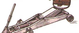
- Place your machine on a hill or in a hole.
- Disconnect the battery terminal and pour out the oil.
- Get inside the car. Remove the handles from the levers, as well as the transfer cases, the element casing and the cover.
- Remove the casing, boot, lock sensor connector. Remove the gearbox lever itself.
- Set up a gear that reverses, remove the locking sleeve.
- Try to mark the cardan flanges and also the transfer case, so that later you can assemble everything in the correct order.
- Remove the cardan (which is the front one) and the washer (which is the oil deflector).
- Did you see the flange (look at the secondary shaft)? Unscrew the nuts of the elastic coupling from it (this is done with a size 19 wrench).
- Unscrew the nuts on the cushions to the very end of the studs and remove the transfer case.
- Now you need to unscrew the bolts from the cylinder and the starter itself, after first removing the cotter pin and the spring next to it. An extension cord is required for this action.
- And move the starter closer to the radiator.
- Disconnect the sensor that controls the lights (reverse), unscrew the muffler clamp, as well as the bolts from the crankcase and the yoke nuts.
- Unscrew the bolts that hold the box closer to the engine. Carefully disconnect it, just try not to let it hang with all its weight on the input shaft.
- Rock it a little from side to side and gradually move it back until you reach the stop.
- Lower the crankcase down and remove the link from the hole.
Installing the car in the inspection hole
Congratulations, you've removed the gearbox! In order to continue the repair, it needs to be disassembled. You should take your time to disassemble it; immediately prepare a work space for yourself. Advice, lay out all the removed parts exactly in the order in which you remove them, this will greatly simplify the reverse process. As you disassemble the device, observe how the bearings, gears, axles behave, whether there are any abrasions, how the input shaft behaves . You may not have to completely disassemble the element, for example, identifying wear on the bearings is very simple, when you remove the bottom cover, move them a little, if any of the bearings move, it means it is worn out and needs to be replaced. So, let's continue the renovation. You need to do the following:
Replacement and repair of Niva Chevrolet gearbox
Replacement and repair are the same thing. In both cases, the gearbox is removed. Only in one is disassembly and troubleshooting, in the other is the process reverse to removal - installation of a new gearbox. Removing the gearbox is performed in the following sequence:
- The gearshift knob is removed from the interior side. To do this, you need to press the lock with a screwdriver. However, you don’t have to remove it at the root, but simply unscrew the handle.
- In order to lighten the weight of the box and prevent oil from leaking, it needs to be drained. There is nothing complicated, the process is similar to draining oil from the engine.
- After this, remove the driveshaft that goes to the transfer case. A mark is required before removal.
- Remove the flush shaft and the mechanism responsible for selecting the desired speed.
- When removing the box, the exhaust pipe will get in the way. Another name for it is “pants”.
- After this, everything attached to the gearbox is removed - the speed sensor and the clutch cylinder. Thus, it is necessary to release everything that is attached to the box and the engine at the same time. All that remains is to unscrew the fasteners and with a partner pull out the gearbox. However, this can be done alone - using a special stand.
There is nothing complicated about repairs either. The box is completely disassembled and defective. It is necessary to inspect the gears for wear. For quality repairs, worn components need to be replaced. Be sure to replace all oil seals and seals. It wouldn't hurt to change the clutch right away. It is recommended to replace the bearings without fail.
It is worth noting that the weak point is 5th gear. She stands higher than the rest and receives less lubrication. Determine the condition of the latch. If it is worn out, the 5th will fly out at speed, which is not very pleasant or comfortable. In addition, it can fly out due to wear of the gear teeth. The unscrewed shank nut also makes its contribution. Do not forget about backlash in the mechanisms - they are unacceptable, otherwise they will manifest themselves in knocking when starting off.
The gearbox is installed in the reverse order of removal.
A necessary tool.
During the process of dismantling the box you will need
- set of wrenches for bolts 10, 12, 13 and 17.
- Set of hexagons from 12 and above
- Container for collecting used oil
- Pliers, Phillips and slotted screwdrivers
- A special stand, suspension or assistant to support the gearbox.
After you have collected all the necessary tools, you can proceed to the actual work.