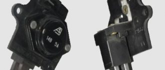
The VAZ 2107 ignition relay is used to turn on the power to the ignition system on carburetor and injection modifications of the “Seven”. Sometimes this part causes the machine to malfunction and has to be replaced. You can localize and fix the problem yourself, without resorting to the services of specialized service stations. This will require a minimum of tools and knowledge of where the relay is located and how to change it correctly.
Purpose of the VAZ 2107 ignition relay (injector and carburetor)
The first VAZ models were not equipped with a separate relay for turning on the ignition. Current was supplied to the coil directly through the contact group of the ignition switch. This decision had certain inconveniences. The ignition system of the VAZ 2107 consumes a lot of current. In addition, when the ignition is turned on, other consumers may simultaneously turn on, increasing the load on the contact group. As a result, the contacts either quickly oxidize and fail. Alternatively, due to heating, the plastic base of the contact group is deformed, which leads to its inoperability. Installing a VAZ 2107 ignition relay (carburetor and injector) reduced the load on the contact group. Only current passes through the contacts on the steering column, feeding the electromagnetic coil of the relay. The main power supply is switched by a relay contact group designed to operate under high current. The presence of the VAZ 2107 ignition relay (injector and carburetor) increased the reliability of the electrical circuit and the service life of the ignition switch contact groups.
Where is the ignition relay for VAZ 2107
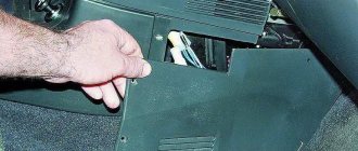
Before checking the performance of a part, it is necessary to find out its location. Many owners of “sevens” do not know where the VAZ 2107 ignition relay is located. Together with the alarm relay, it is attached under the “dashboard” behind the instrument panel. Therefore, in order to see it, check and change it, you will have to work a little with a screwdriver to remove the VAZ 2107 instrument cluster.
Examination
The easiest way to test a switch is to try replacing it with a known good one. But this can only be done if a working switch is at hand. It is not advisable to buy a new unit just to test the operation of the old one. There is a cheaper and not particularly complicated way. To test the switch, you only need a standard set of keys and a test lamp. This is enough to verify the presence or absence of pulses supplied to the ignition coil. Before checking the switch, make sure that “plus” is supplied to it and the ignition coil. Also check the connection contacts of the Hall sensor and the functionality of the sensor itself. Checking the VAZ 2107 ignition switch is performed as follows:
- turn off the ignition;
- unscrew the nut on the ignition coil and disconnect the brown wire marked “K” (the wire goes to connector “1” on the switch);
- connect a test lamp to the gap between the wire terminal and the coil terminal;
- turn on the ignition;
- turn the key and start the starter.
A flashing light indicates a working switch. If the lamp does not light, the switch needs to be replaced.
Replacing a VAZ 2107 switch
To replace the switch, you must complete the following steps:
- turn off the ignition;
- disconnect the wire block from the switch connector;
- unscrew the fastening nuts;
- remove the old switch and put a new one in its place;
- tighten the fastening nuts;
- connect the wire block to the connector.
How to check and replace the ignition relay on a VAZ 2107
To check and replace the ignition relay, you will need:
- slotted screwdriver;
- crosshead screwdriver;
- key to 10.
You need to start by dismantling the instrument panel. Before starting work, disconnect the negative cable from the battery. To remove the instrument panel, you must perform the following steps:
- Use a slotted screwdriver to release the latches of the heating system adjustment handles;
- remove the handles from the levers;
- remove the central air duct nozzles by prying them off with a screwdriver;
- pull out the heater engine operating mode switch;
- remove the wire ends from the switch;
- pull out the self-tapping screw plug by prying it with a screwdriver;
- Unscrew the self-tapping screw securing the instrument panel using a Phillips screwdriver;
- unscrew the nut securing the daily mileage reset handle;
- push the handle inside the instrument panel;
- remove the right edge of the instrument panel;
- unscrew the nut securing the speedometer drive cable;
- disconnect the hose from the econometric fitting;
- disconnect the wire connectors from the instrument cluster;
- remove the instrument panel.
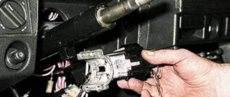
The ignition relay is mounted on a bracket located under the instrument panel. To remove the relay, you need to use a 10 mm wrench to unscrew the nut that attracts it to the bracket. To check the functionality of the relay, you need a multimeter or an indicator lamp. You can test the operation of the relay directly on the car or by powering it from an autonomous 12 volt source. When voltage is applied to pins 85 and 86 of the relay, the contacts between pins 30 and 87 should close. If this does not happen, the VAZ 2107 ignition relay needs to be replaced. This is done like this:
- unscrew the fastening nut;
- disconnect the wire block from the ignition relay;
- install a new relay;
- connect the wire block;
- secure the relay with a nut.
After replacing the relay, you need to reinstall the dashboard. To do this, follow these steps:
- connect the wire blocks to the instrument panel;
- tighten the nut securing the speedometer drive cable;
- attach the hose to the econometer;
- insert the instrument cluster into place and press on it until the latches lock;
- secure the daily mileage reset handle;
- tighten the self-tapping screw securing the instrument panel;
- close the self-tapping screw with a plug;
- connect the wires to the heater operating mode switch;
- snap the switch into place;
- install nozzles for the central air duct of the heating and ventilation system;
- install handles for adjusting heating and ventilation modes.
This completes the replacement of the VAZ 2107 ignition relay. You can connect the ground wire to the battery and check the functionality of the ignition system.
Installing an electronic BSZ instead of a contact one
Today it is very rare to find a “seven” with contact ignition. With the arrival on sale of switches, distributors and coils for electronic spark generation systems, owners of classics began to massively re-equip their cars.
What is included in the BSZ kit
The process of converting a contact system into an electronic one is quite simple, and also inexpensive. The cost of an electronic ignition kit for a VAZ 2107 is about 2,500 rubles. It includes:
- transistor switch type 3620.3734 with connector;
- coil 27.3705;
- contactless distributor type 38.3706;
- connecting wires.
In addition, you will need spark plugs (preferably new ones) with a gap of 0.7–0.8 mm and a set of high voltage wires. Coil type B-117A (used in a contactless system) is not suitable for electronic ignition . Its characteristics do not correspond to those of other equipment in the circuit.
Video: review of BSZ elements for “classics”
Required Tools
To complete the work you will need:
- 8, 10 and 13 mm wrenches;
- screwdriver with a Phillips blade;
- drill;
- spark plug key;
- 36 mm wrench or with a ratchet mechanism for turning the crankshaft;
- self-tapping screws;
- pliers.
Work order
Work on converting the ignition system into a contactless one is carried out in the following order:
- Disconnect the terminals from the battery. We remove the battery and put it aside.
- Remove the high voltage caps from the distributor cap and from the spark plugs.
- Using a special wrench, unscrew all the spark plugs. We screw new ones in their place.
Video: installing BSZ on a “classic” VAZ
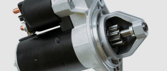
Repair of starter retractor relay
However, some car owners repair it themselves. But you need to know how to disassemble the starter solenoid relay. If the relay is collapsible, then it can be repaired. In the case of non-dismountable parts, repairs are also possible, but to a small extent. In particular, when burning “nickels”, improving and cleaning the contact. If one of the windings burns out or short-circuits, then such relays, as a rule, cannot be repaired.
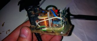
For further work you will need a flat blade screwdriver, as well as a soldering iron, tin and rosin. Disassembling the relay begins with the fact that it is necessary to remove the core from it. After this, two are unscrewed that hold the top cover where the coil contacts are located. However, before removing it, it is necessary to unsolder the mentioned contacts. It is not necessary to solder both contacts. Usually, to get to the “nickels”, it is enough to unsolder only one contact and lift the cover on one side.
Next, you need to unscrew the bolts holding the “nickels” from the top side and remove them. If necessary, they need to be reviewed. That is, clean them with sandpaper in order to get rid of carbon deposits. A similar procedure must be performed with their seats. Using a plumbing tool (it is best to use a flat blade screwdriver), clean the seat, removing dirt and carbon deposits. Reassembling the relay housing occurs in the reverse order.
Disassembly and assembly of a collapsible relay occurs in the same way. To do this, you need to unscrew the stud bolts and disassemble its body. This will give you access to the internal elements of the device. The audit work is carried out similarly to the above algorithm.
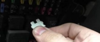
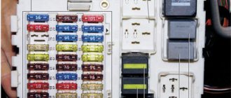
Replacing fuses in the mounting block
Open the cover of the mounting block.
The serial numbers of the pin fuses are indicated on the underside of the cover and on the panel of the unit. There, on the cover, are the symbols of the protected circuits.
In the old design of the mounting block, which is equipped with some cars, the fuses are located in numerical order from left to right.
The condition of the fuse element of a pin-type fuse is visible through a window on top of its body.
To replace fuses and relays, the mounting block is equipped with special plastic pullers.
If a puller is not available, the fuse and relay can be removed with pliers.
Replacing the additional headlight cleaner fuse
Additional headlight wiper fuses (2A rating) protect the motor windings.
They are installed on the supply wires next to the gearmotors.
To check and replace faulty fuses, unscrew the fuse cover
Replacing fog light circuit fuses
To check and replace the fog light circuit fuse, pry it up with a screwdriver and remove the two middle switches from the radio panel.
Using a screwdriver, we press in turn the two fasteners securing the lower insert of the radio panel
We take out the insert.
Remove the fuse housing from the panel
We unscrew its cover and replace the overheated fuse
Contactless ignition system
The ignition system (IS) serves to create a pulse voltage and timely ignite the combustible mixture in the combustion chambers of the power unit. It is the main part of the vehicle's energy supply system.
The evolution of the “seven” ignition began with a contact-type mechanism. Its feature was the process of generating an electrical impulse using a group of contacts located in the distributor. The constant mechanical and electrical loads to which the contacts in such a system were subjected led to the fact that car owners very often had to clean them, change them and adjust the gap between them. In principle, this was the only significant drawback of contact-type ignition, and drivers, when problems arose with ignition of the mixture, knew exactly what needed to be checked and repaired.
In the early 90s of the last century, the “seven” received contactless ignition. It made the life of the owners of these cars much easier, because in its design there were no longer any burning contacts that required constant adjustment. They were replaced by an electronic switch that does not require any maintenance.
The design of the contactless ignition system and the principle of its operation
The contactless ignition system (BSI) of the VAZ 2107 includes:
- electronic (transistor) switch;
- transformer coil (two-winding);
- distributor (distributor) with Hall sensor, contact cover and slider;
- set of high-voltage wires;
- candles.
Each of these elements is a separate part and performs its functions independently of other components. Sparking in a VAZ 2107 engine with a non-contact ignition system occurs according to the following algorithm:
- When voltage is applied to the starter, its rotor begins to rotate the crankshaft, which, in turn, rotates the distributor shaft with the slider.
- The Hall sensor reacts to this rotation, registers the rotation of the distributor shaft and transmits a signal to the switch. The latter, having received a signal from the sensor, turns off the current supplied to the primary (low-voltage) winding of the coil.
- At the moment the current is turned off, a powerful voltage pulse occurs in the secondary winding of the transformer, which is transmitted through the central wire to the slider (moving contact) located at the end of the distributor shaft.
- The slider, moving in a circle, alternately comes into contact with four fixed contacts located in the distributor cover. At certain moments, it transfers tension to each of them.
- From the stationary contact, current flows through a high-voltage wire to the spark plug, causing sparking at its electrodes.
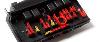
Repairing a broken track
The procedure looks like this.
In severe cases, when a large number of tracks are damaged or the board itself is burned out, it is recommended to replace the entire panel.
The fuse box of the Lada 2107 is not complex in design or difficult to maintain. The car has a minimum number of inserts and is easy to maintain even by a novice driver.
Specialization : Graduated from the State Automobile University, worked for 20 years at GAZ-56, now I drive a Zhiguli.
Source
What are the fuses on the VAZ-2110 responsible for?
Decoding fuses.
License plate lamps. Instrument lighting lamps. Side light indicator lamp. Trunk light. Left side marker lamps
Left headlight (low beam)
Left headlight (high beam)
Right fog lamp
Door window motors
Portable lamp (socket)
Engine cooling fan electric motor. Sound signal
Rear window heating element. Relay (contacts) for turning on the heated rear window
Recirculation valve*. Windshield and headlight cleaners and washers ( wiper fuse ). Relay (coil) for turning on the rear window heating
Starboard side marker lamps
Right headlight (low beam)
Right headlight (high beam). High beam warning lamp
Left fog lamp
Electrically heated seats. Trunk lock lock
Relay-breaker for direction indicators and hazard warning lights (in hazard warning mode). Hazard warning lamp
Interior lighting lamp. Individual backlight lamp. Ignition switch illumination lamp. Brake light bulbs. Clock (or trip computer)
Glove box lighting lamp. Heater controller ( heater fuse ). Cigarette lighter fuse for VAZ 2110, VAZ 2111, VAZ 2112.
Locking door locks. Relay for monitoring the health of brake light lamps and side lights. Direction indicators with warning lamps. Reversing lamps. Generator excitation winding. On-board control system display unit*. Instrument cluster. Clock (or trip computer)
Rear fog lamps