Hydraulic cuffs are a necessary element that is installed in various connections of hydraulic devices in order to give them the greatest tightness. These products are made from rubber materials, namely polyurethane and rubber, and serve as a seal that ensures stable and safe operation of the mechanism.
There are two types of hydraulic seals, each of which is used in hydraulic devices that operate by reciprocating action. The first serves to seal the rod connection, and the second, in turn, performs the same tasks, only in the cylinder.
Modern industry, equipped with many different machines and devices of hydraulic type, simply cannot exist without such rubber goods, since hydraulic cylinders are present as a structural component in a variety of cargo and specialized equipment.
Of course, such equipment must have reliable braking systems, the serviceability of which directly affects human safety. Hydraulic seals are an integral part of these systems because their presence creates a good tight seal and prevents brake fluid from leaking out.
The device of the VAZ brake system
The brake system of Togliatti-made cars is quite simple; the vehicle consists of the following main parts:
- pedals, which are pressed to achieve braking;
- brake master cylinder (MBC), it transmits the force of pressing the pedal through hydraulics to the working cylinders, respectively, to the wheels. GTZ VAZ - dual-circuit, the circuits are divided to transmit fluid pressure to the front and rear wheels;
- a vacuum booster that makes it easier to press the pedal;
- tubes that connect the elements of the vehicle;
- brake working cylinders (RTC);
- pads (drums) and discs;
- brake distributor (pressure regulator).
When you press the brake pedal, the piston in the brake fluid compressor compresses the brake fluid and transmits its pressure to the brake pedal. The pistons of the working cylinders are expanded under the influence of hydraulics, moving the pads towards the discs or drums. The movement of the wheels slows down, and thus the car slows down.
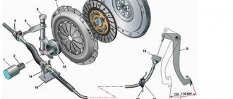
Device
The design of the front caliper and the rear brake cylinder of a VAZ car differ in the appearance of the body and main parts. The disc brake device consists of the following main parts:
1 - Piston. 2 - Boot. 3 - Sealing collar. 4 - Caliper body. 6 - Air fitting. 7 - Springs that press the pads. 12 - Pads.
The drum brake uses the following parts:
2 - Bleeding fitting. 3, 11 - Anther. 4, 10 - Piston. 6, 9 — Piston seal. 7 - Housing.
Malfunctions occurring in the brakes
From time to time, various malfunctions occur in the vehicle, and the working and master cylinders also often fail. The following breakdowns occur at the RTC:
- the piston gets stuck in one of the positions;
- the inner surface wears out;
- The sealing cuffs fail (tear or swell).
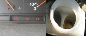
The main sign of a faulty condition is the appearance of smudges (leaks) of brake fluid (FL) from the RTC. If the pads are worn down to bare metal, the pistons in the RTC extend too far, and as a result, the brake fluid may leak and the brakes will fail.
In the GTZ, the piston can also jam, the internal cavity of the mechanism can wear out or rust, and the cuffs can leak. Symptoms of a GTZ malfunction are as follows:
- when braking, the brake pedal (BP) “fails”, the effectiveness of pressing disappears, this usually happens when there is a small leak from the turbocharger;
- braking occurs at the very end of the pedal stroke, and you have to press the PT several times to brake;
- there are no brakes on the front or rear wheels, this happens if one of the GTZ circuits does not work.
You cannot drive with faulty working and master brake cylinders; the parts should be replaced immediately.
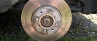
Front brake
A metal disc is rigidly fixed directly to the hub. The brake disc is secured using:
- Small conical studs that serve as guides for the wheels.
- The bolts that secure the wheel to the hub.
The rotation speed of the disk and wheel will always be the same. Therefore, in order to brake a car, it is necessary to stop all its wheels. To do this, you need to clamp the disc using pads and brake calipers.
The calipers have two parts - external and internal. On the inside there is a cylinder, a steel piston is installed in it. Under the influence of the pressure created by the main brake cylinder of the VAZ-2109, this piston moves and acts on the block located from the inside. At the same time, the outer part of the caliper moves towards. When the pressure in the system decreases, the pads return to their original position under the action of springs.
Replacing the master brake cylinder
Replacing the GTZ on VAZ classic cars (2101-07) is not difficult; you can do this work yourself. To perform such an operation you will need the following tool:
- 10mm wrench (or special bleeder wrench);
- Phillips screwdriver;
- combination wrench for 13 (you can additionally use a head with a knob and a ratchet for convenience).
It is not necessary to use a pit or a lift to perform the work; replacement can be done outside in dry weather or in the garage. The work should be performed in the following sequence:
- unscrew the three brake pipes from the bottom of the device (key for ten);
- loosen the clamps of the two hoses (at the bottom of the GTZ), pull off the hoses;
- unscrew the two nuts securing the GTZ to the vacuum booster (you need a 13mm wrench or a socket with a wrench);
- We dismantle the part, install the new gas turbine unit in place, and reassemble it.
After the operation, you should add fluid to the vehicle reservoir, then be sure to bleed the brakes well.
Replacement or repair?
The price of the VAZ-2109 master brake cylinder is about 1000 rubles. The repair kit will cost half as much. But the feasibility of its installation is highly controversial. When repairing, you will need to do the following:
- Drain the liquid from the expansion tank.
- Remove the expansion tank.
- Unscrew the pipes that are located on the brake cylinder.
- Remove the two nuts that secure the master cylinder body to the vacuum booster.
- Loosen the locking bolt that holds the first piston in place.
- Pull the piston out of the cylinder. This must be done carefully so that the spring does not jump out. Try not to lose all the elements.
- Loosen the locking bolt holding the second piston and remove the element from the cylinder.
Replacing brake cylinder 2114
The work of replacing the GTZ on VAZ 2108-15 models is carried out approximately the same way, there are only some design differences.
We make the replacement as follows (using the example of the VAZ-2114):
- Unscrew the four tubes on the sides (two on the left and two on the right). It is better to use a special pipe wrench; you can roll up the edges of the nuts with an open-end wrench;
- unscrew two thirteen nuts securing the GTZ to the “vacuum”;
- We remove the old spare part and install a new one, not forgetting to bleed the brakes at the end of the work. At this point, the replacement of cylinder 2114 can be considered complete.
Replacing the brake cylinder repair kit
If in the GTZ 2114 the inner surface of the cylinder itself is not yet worn out, you can replace the insides of the mechanism by installing a new repair kit. The repair kit consists of four cuffs:
- three cuffs are the same, they are the same as on models 2101-07;
- one o-ring 2108.
Changing the repair kit is very simple:
- pour the liquid out of the GTZ;
- dismantle the plastic tank;
- unscrew the front stopper (made in the form of a plug);
- we take out all the contents (pistons, o-rings, springs), change the cuffs, and install the entire mechanism in the reverse order. Nothing should be mixed up here, otherwise the unit being repaired will not work.
Repairing the GTZ on VAZ models is not always advisable - if the mirror surface inside the mechanism is worn out, replacing the brake cylinder repair kit will not solve the problem, the GTZ will also leak. Most often, on VAZ cars, the entire master brake cylinder is replaced - a new assembled part costs around one thousand rubles, and the repair turns out to be unjustified.
Manufacturers of repair kits
Popular manufacturers of brake master cylinder repair kits used in our country are the following companies:
- JSC "Volzhskrezinotekhnika" The company produces repair kits for domestic cars - “Zhiguli”, “Moskvich” and other popular brands (for Moskvich 2140 it consists of 3 pairs of cuffs, each of which has its own cat. no. 412-3505045, 042 and 036).
- FENOX Global Group (Belarus). The company produces a wide range of repair kits for domestic and foreign cars. In particular, for VAZ-2101, 2106, 2107 and VAZ-2121, the catalog number of the GTZ repair kit is KPT1963C3, the price of the repair kit is $1.3...1.7. And for Moskvich 2140-3505032.
- PJSC “Balakovorezinotekhnika”. Manufacturer of rubber products, producing more than 6,000 items and ensuring uninterrupted operation of VAZ, KamAZ, GAZ automobile conveyors (catalog number for the GTZ repair kit for VAZ 2108-09 cars is 21080350503300, repair kit from the manufacturer, price - about $1).
- Basalt company. Russian manufacturer producing GTZ repair kits for domestic cars.
- SEIKEN. A manufacturer from Japan that produces repair kits mainly for Japanese cars (for example, HONDA, kit catalog number - SK62811, price of a brake master cylinder repair kit - $16...18).
- Aisin Seiki Co Ltd (or simply Aisin). Another Japanese company producing components for car assembly plants. It produces a lot of products for Toyota.
- SEGURIDAD INDUSTRIAL, SA (SEINSA), Spain. Manufactures products, including GTZ repair kits under the AUTOFREN trademark. Used in many European cars. (for example, the catalog number of the set is D1298, the price is $2...3).
- DELPHI company, USA. Its repair kits are used on both American and European cars (for example, Mercedes).
- ATE, Germany. Produces repair kits for European cars (for example, catalog number 03037030232, the price of a GTZ repair kit is $20...25).
I would like to remind you that...
Using the GTZ repair kit, you can eliminate only minor malfunctions in its operation - brake fluid leakage, smooth operation of the pedal, adjustment of the brake system. If the cylinder is physically damaged, then in most cases it must be completely replaced, and unfortunately, replacing the cuffs is not enough.
Upon completion of the work on replacing the master cylinder repair kit, do not forget to bleed the brake system to ensure that it is tight and free of air. And before heading out on the road, test the effectiveness of the braking system near the garage, while observing safety rules.
Replacing brake cylinder 2107
If the replacement operation on a VAZ classic is not performed on a car lift, it is more convenient to do the work sequentially - first on one side, then on the other side of the rear wheel. To perform the work, the vehicle must be placed on a level surface, then proceed as follows:
- We turn off the engine, set the car to speed, and put chocks under the front wheels. Don’t forget to fully release the handbrake;
- loosen the wheel nuts of the rear wheel, jack up the car and remove the wheel;
- To prevent the car from going anywhere, it is advisable to place a “tragus” next to the jack;
- remove the brake drum - use a 12 mm combination wrench to unscrew the two guides;
- the drum usually comes off tightly, so it should be tapped from behind with a hammer through a piece of wood. You cannot hit the part with an iron hammer; the drum can split;
- unscrew the brake pipe from behind the cylinder, also 2 ten bolts securing the RTC itself;
- pull out the cylinder, freeing it from the pads;
- We install the part prepared for replacement (it is important to get the pads into the slots on the RTC pistons, we fasten all the removed parts in their places;
After the work has been done, it is necessary to top up the fuel injection system reservoir and bleed the brakes.
Replacing the brake cylinder VAZ 2109
The RTC on the rear axle of the 2109 wheels is changed according to the same principle as on the VAZ classic; the wheel and drum are also removed, the tube and two cylinder fastenings are unscrewed with a ten key. It often happens that the tube and RTC bolts on the support disk boil; to remove them carefully, you need to spray the connections with WD-40, and wait 15-20 minutes before unscrewing. The brake pipe nut will be easier to unscrew if you gently tap the metal around it with a hammer. When tapping, it is important not to break the bleeder fitting.
Replacing brake cylinder 2109 is not a difficult task, and many drivers can do this work themselves.
Pressure regulator
1 – pressure regulator housing;
2 – piston; 3 – protective cap; 4, 8 – retaining rings; 5 – piston sleeve; 6 – piston spring; 7 – body bushing; 9, 22 – support washers; 10 – sealing rings of the pusher; 11 – support plate; 12 – pusher bushing spring; 13 – valve seat sealing ring; 14 – valve seat; 15 – sealing gasket; 16 – plug; 17 – valve spring; 18 – valve; 19 – pusher bushing; 20 – pusher; 21 – piston head seal; 23 – piston rod seal; 24 – plug; A, D – chambers connected to the main cylinder; B, C – chambers connected to the wheel cylinders of the rear brakes; K, M, N – clearances The pressure regulator regulates the pressure in the hydraulic drive of the brake mechanisms of the rear wheels depending on the load on the rear axle of the car. It is included in both circuits of the brake system and through it brake fluid flows to both rear brake mechanisms.
Replacing the front brake cylinder
The following calipers are installed on the front wheels of VAZ cars:
- in a VAZ classic car, two front brake cylinders (FTC) are attached to the caliper brackets;
- on VAZ 2108-15 models, one PTC is installed on each side of the front axle.
Replacing the front cylinder 2109 is not difficult, it is also easy to do yourself:
- we put the car on a flat area (the work can be done without a pit and a lift), we put tackles under the rear wheels;
- jack up the car, take off the front wheel;
- unscrew the two caliper fasteners with a hexagon;
- loosen the brake hose nut;
- bend the locking washers on the upper and lower bolts, unscrew the cylinder fastenings to the caliper bracket
- we move the PTC to the side along with the bracket;
- disconnect the cylinder from the bracket, then from the hose so that the brake fluid does not leak; after disconnecting the PTC, it is better to immediately direct the hose upward;
- we install another, new spare part, and perform the assembly.
Replacing the brake cylinder VAZ 2101-07
On VAZ classic cars, the PTC changes a little differently than on front-wheel drive VAZ cars. The front caliper on the “Classic” can be changed as a whole assembly, but it is also possible to replace only the cylinders. The work is carried out as follows:
- We also put the car on the platform, remove the front wheel;
- unscrew the bolts securing the caliper itself;
- move the caliper to the side, disconnect the hose;
- We take out the pads from the caliper and twist the brake pipe from it.
- if the pins for securing the pads cannot be removed, they will have to be cut with a grinder, then installing new fasteners;
- the brake cylinders are mounted on a bracket in the guides, and they are removed either with a pry bar or by gently tapping with a hammer;
- we install other cylinders, a tube and pads with pins, and complete the assembly.
Replacing the brake cylinder cuff
If desired, on VAZ cars you can not change the entire rear working cylinders, but only replace the cuffs. To do this, you need to disassemble the RTC - remove the pistons and spring, remove the old cuffs from the pistons and install new ones. It is advisable to repair the RTC only if the cylinders did not last long, but they began to leak. The thing is that on VAZ cars the RTCs are very inexpensive, it is advisable to change the rear cylinders as a whole - replacing the cuffs is often unjustified.
How to service the master cylinder
The design of the brake system on nines is approximately the same as on classic models. The only difference is that the parts of the VAZ-2109 brake system are much stronger and more powerful, since the car is capable of developing higher speeds, therefore, it needs to be stopped faster.
There is no need to service the master cylinder if it is functioning properly. But try to change the brake fluid, top up if necessary and make sure that there is no leakage in the system. If a leak appears from the master cylinder, it must be repaired or completely replaced.
Leveling up
After replacing any cylinder in the vehicle, it is necessary to bleed the brakes. Bleeding on any car always begins with the furthest wheel from the GTZ. On all VAZ cars, first of all, they start pumping the brakes from the rear right wheel, then move to the rear left, right front, and the front left wheel is pumped last. If the brake pedal takes at the very end or is hard, bleeding should be repeated, the work should be done according to the same scheme again.
Some tips
- If you start having problems with the brakes, first of all you need to carry out an external inspection of the vehicle: check the fluid level in the reservoir, make sure that the front/rear cylinders are not leaking. There should not even be stains of brake fluid in the brake hydraulics.
- “Brake fluid” must be filled with the same brand; it is recommended to completely replace the brake fluid at least once every two years.
- If faults are identified in the gas turbine engine, and it has already served for at least a year, it is more advisable to replace it completely than to repair it. The same can be said about the rear working cylinders.
- Before changing the turbocharger, the brake fluid should be removed from it; this operation is usually done using a syringe.
- Usually a leak in the master cylinder is not visible, but if there is any suspicion that this part is faulty, you should remove the main cylinder - there will be traces of leaks at the rear, and this indicates its faulty condition.
- If, during an external inspection, cracks were found on the brake hoses, it is better not to take risks and immediately replace the defective parts.
For every motorist, a car breakdown is a disappointment, but many problems can be solved without a service station thanks to a ready-made repair kit. Such sets also exist for master brake cylinders, but we’ll figure out how to use them below.
Functions of the master cylinder
This element can rightfully be called the heart of the entire braking system. It converts the force applied to the pedal into hydraulic pressure. Essentially, it performs the functions of a hydraulic pump and is responsible for the correct supply of fluid to each wheel. Structurally, it is divided into two sections, one is responsible for the operation of the front wheels, and the second - the rear. Thus, even if the performance of one of the circuits is impaired, the second will still complete the task. On rear-wheel drive vehicles, these sections are divided along axles.
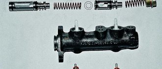
The main elements of the brake master cylinder (MBC) are a body, two pistons, return springs and a reservoir, it also contains a lock washer and rubber gaskets. The principle of operation of the node is as follows. The piston moves along the cylinder and closes the compression hole; pressure is created in the first circuit, causing movement of the second circuit. The resulting void is filled with liquid. The spring acts as a limiter and returns the pistons to their original places.
Causes of breakdowns and their symptoms
One of the main reasons for brake master cylinder failure is uneven distribution of fluid in the system, leading to circuit failure. The wear of the sealing collars located at the points where the rod enters the cylinder has a negative effect. It is also possible that scuffs may appear on the pistons and deformation of their return springs with rubber cuffs.
In addition, the compression hole becomes partially or completely clogged. The above malfunctions can be caused by poor-quality brake fluid. Any failed part should be urgently dismantled and a new one installed in its place; if the cylinder mirror is faulty, the entire assembly must be replaced. Moreover, you cannot hesitate, since the correct operation of the gas turbine engine is one of the keys to your safety.
Much can be understood by the performance of the brake pedal. So, if it has a reduced stroke, then most likely the reason lies in the compression hole. It may be clogged or blocked. It may also be due to the lack of clearance between the gas turbine seal and the piston. When the piston gets stuck, the channels are blocked and the cuff is deformed, the pedal does not make a full stroke. But if it moves too easily, then the cause is a hydraulic fluid leak, and the rubber bushings need to be replaced. Sticking of the piston is indicated by the wheels braking when the pedal is released.
Wheel cylinder
1 – block stop;
2 – protective cap; 3 – cylinder body; 4 – piston; 5 – seal; 6 – support plate; 7 – spring; 8 – crackers; 9 – thrust ring; 10 – thrust screw; 11 – fitting; A – slot on the thrust ring The brake mechanism of the rear wheel (Fig. Brake mechanism of the rear wheel) is drum, with automatic adjustment of the gap between the shoes and the drum. The automatic clearance adjustment device is located in the wheel cylinder. Its main element is a split thrust ring 9 (Fig. Wheel cylinder), installed on the piston 4 between the shoulder of the thrust screw 10 and two nuts 8 with a gap of 1.25–1.65 mm.
The thrust rings 9 are inserted into the cylinder with tension, providing a shear force of the ring along the cylinder mirror of at least 343 N (35 kgf), which exceeds the force on the piston from tension springs 3 and 7 (see Fig. Brake mechanism of the rear wheel) of the brake pads.
When, due to wear of the linings, the gap of 1.25–1.65 mm is completely removed, the shoulder on the thrust screw 10 (see Fig. Wheel cylinder) is pressed against the shoulder of the ring 9, as a result of which the thrust ring moves after the piston by the amount of wear. When the braking stops, the pistons are moved by the force of the tension springs until the cracks stop against the shoulder of the thrust ring. This automatically maintains the optimal clearance between the pads and the drum.
Diagnostics and repair - replacement of repair kit
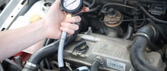
Where to start diagnosing the brake system and GTZ? First of all, it is necessary to carry out a visual inspection, since any damage - drips, wet spots on the body, cracks, etc. - are very alarming signs. Are there any external defects found? Then you should check the brake pedal travel, it should be smooth and soft, jamming and failure are unacceptable. If everything is in order, then the next step is to test the braking system in action. You can check the dismantled master brake cylinder for leaks only at a service station or if you have a special stand. All its elements are treated with alcohol, and for rubber gaskets only replacement is suitable. Pay special attention to the GTZ mirror; chips, scratches and other damage are not allowed on it.
If damage incompatible with life is detected, you can replace the brake master cylinder repair kit yourself. Naturally, the first thing to do is dismantle the part. It is installed in the engine compartment housing. Having reached the unit, drain the brake fluid; to do this, you need to pry off the corresponding clamps with a screwdriver and pull out the pipes. After which the studs are unscrewed and the GTZ can be freely removed.
When to change cuffs?
Any brake system contains a large number of metal pipes connected using metal fasteners and sealed with cuffs. The seals prevent brake fluid from leaking through moving parts and provide a sealed brake system.
The main signs of a cuff malfunction are a decrease in braking efficiency and a decrease in the level of brake fluid in the reservoir. First you need to find the specific location of the leak. To do this, you need to examine each wheel of the car one by one. If there are traces of brake fluid on it, then this is a clear sign that this brake cylinder has a faulty seal that needs to be replaced. After this, the brake lines and master cylinder are subject to diagnosis.
Found traces of brake fluid indicate a violation of the tightness of the element, which occurs due to worn out seals.
Installing a new cylinder
The layout of the VAZ-2109 master brake cylinder is the same as on classic series cars:
After this, you need to install new cuffs and pistons and fix the device in place. But it is much better to change the main brake cylinder of the VAZ-2109. How to do it yourself:
- Secure the cylinder body with two nuts on the vacuum booster.
- Install the brake pipes.
- Secure the expansion tank to the cylinder.
After this, it is necessary to fill the system with fluid and bleed the brakes. If this is not done, there will be air pockets inside the system that will not allow maximum braking efficiency to be achieved.
How to change the brake master cylinder cuff + Video
If the fault affects the master brake cylinder, then you need to purchase a special repair kit, because it contains more than one cuff.
- Set the vehicle to speed and drain the brake fluid from the reservoir and brake cylinder. To do this, unscrew the drain bolt with a spring at the end of the cylinder, and press the pedal vigorously to squeeze out the remainder.
- Next, you need to unscrew the lines from the brake master cylinder. Their fastenings are made in the form of metal fittings that can be unscrewed with a wrench. Now unscrew the cylinder fasteners and remove it.
- This will be followed by disassembling the cylinder and replacing the old parts with new ones. Pay attention to the location of the cuffs inside the cylinder. Their installation must be strictly identical, otherwise you risk reducing braking efficiency many times over.
During the installation process, be careful and do not use too sharp tools. This is due to the fact that the slightest crack in the seal will lead to its rapid wear, which, in the best case, will force you to tamper with the brake system again, and in the worst case, scrap the broken car.
After repairing the cylinder, it is installed in place, and the line fittings are connected to it. Fill the brake fluid and bleed the system to get rid of air, which also impairs braking.
This completes the replacement of the master cylinder cuff. As you can see, it's not difficult at all.
VAZ 2109,2108,2107,2106,2105,2104,2103,2102,2101, 2170, Tavria, Chevrolet Niva
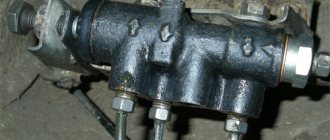
The main brake cylinder 2 of the tandem type is installed under the engine hood and is secured with its flange to two studs, which are welded to the pedal bracket amplifier.
Its cast-iron body 2 (Fig. 1), which has a through hole with a diameter of 19.05 mm, contains two pistons. The piston 5 located at the rear serves to actuate the front brakes, and the front piston 3 serves to actuate the rear brakes.
At the front, the hole in the master cylinder is closed by plug 1, into the recess of which a twisted cylindrical spring 7 enters. With its second end, it rests against piston 3 and, in the absence of action on the pedal, takes it to the rearmost (right in the figure) position.
The shank 8 of the installation bolt 8 protrudes into the cylinder cavity and fits into the longitudinal groove of the piston 3, thus limiting its backward movement.
In the front part of the steel piston 3 there is an annular groove into which a rubber reindeer ring 14 is installed. Spring 13, resting on plate 12, tends to press the rear end of this ring against the rear shoulder of the piston annular groove. The installation ring 15 is placed loosely on the piston and is located on its groove in such a way that when the sealing ring 14 moves back (to the right), it serves as a stop for the end of the ring 14.
The rear end of the piston 3 ends with a shank on which an o-ring 9 sits, separating the rear brake drive cavity (R.T.) from the front brake drive cavity (F.T.).
A twisted cylindrical spring rests on another sealing ring through a washer, which acts as a spacer between the pistons. Under its influence, the piston, in the absence of pusher pressure, moves to the rearmost position, determined by the installation bolt 11 (see Fig. 1). On the back of the piston 5 of the front brake drive there is an annular groove in which a rubber cuff 6 is placed, which prevents brake fluid from leaking from the cylinder and protects the working area of the cylinder from contamination.
When moving the pedal, pusher 2 rests against the hemispherical bottom of the cone bore at the rear end of piston 5. A rubber protective cover, placed on the rear end of the master cylinder, protects it from dust and dirt.
The design of both pistons is fundamentally the same, and they differ only slightly, as mentioned above.
Five holes are drilled in the bosses on the top of the body: b and d (see Fig. 1), connecting the working cavities of the cylinder with tanks containing brake fluid; through hole a and a tube, the drive cavity of the rear brakes is connected to the brake mechanisms of the rear wheels and through two holes (see Fig. 1) to the brake mechanisms of the front (left and right) wheels.
Due to the fact that the main brake cylinder is mounted on a bracket common with the pedals, which has a closed shape and spaced-apart attachment points, high assembly accuracy and rigidity of the connection of the command mechanisms of the hydraulic brake and clutch drives are ensured.
Operation of the main cylinder of the hydraulic brake drive. The master brake cylinder described above differs significantly from those previously used on domestic passenger cars. The use of separate, independent drives for the brakes of the front and rear wheels significantly increases the safety of the vehicle, since if one circuit fails, the second continues to work.
The main brake cylinder operates as follows. When the pedal is released, its pusher is in light contact with the supporting surface of the piston (position 1), without interfering with the movement of the pistons under the influence of springs 7 and 10 to the rearmost (in Fig. 1, to the extreme right) position.
The movement of the pistons occurs until their edges of the bores stop against the installation bolts 8 and 11. The installation rings 15, loosely placed on the pistons, also rest with their rear ends against the shanks of the installation bolts and, due to the fact that the stiffness of the springs 7 and 10 exceeds the stiffness of the springs 13, they hold the sealing rings 14 from contact with the piston.
In this position, the sealing rings, which also perform the functions of valves, do not interfere with the communication of the working cavities. t.n.t. through compensation holes 16, annular slots (see Fig. 1, a) and holes b and d with corresponding tanks.
When you press the brake pedal, the pusher moves the front brake piston to the left. In this case, the annular gap between the end of the sealing ring 14 and the piston 5 disappears, since the installation ring 15 does not prevent the sealing ring from moving all the way to the shoulder of the recess of the piston 5. In this case, the connection between the piston cavity and the nutrient tank is stopped.
This ends the free play of the piston, which when measured at the center of the pedal platform is 3-5 mm. Further movement of the piston is already a working stroke and is accompanied by an increase in pressure in the cavity of the piston, under the influence of which the sealing ring 9, together with the piston 3, moves to the left.
The “floating valve” assembly shown in Fig. 1, a is the same for both pistons, and therefore, after moving piston 3 to the left by an insignificant amount, communication with cavity h. t. with the nutrient tank will stop in the same way as it happened a little earlier at the cavity of the p.t.
With further movement of the brake pedal, the pressure in both working cavities will increase evenly, due to the fact that with a working hydraulic drive system, the movement of piston 3 occurs under the influence of a pressure difference, which is automatically eliminated, since piston 3 is floating.
As the pressure in the working cavities increases, the sealing rings 14 will fit more tightly to the cylinder walls and to the end of the annular recess under the influence of liquid pressure, which improves the sealing of the working cavities.
Thanks to the unique shape of the outer part of the sealing rings, even at high pressure in the working cavities of the cylinder, satisfactory lubrication of the rubbing surfaces and smooth movement of the pistons is ensured.
This type of sealing ring design was used for the first time on domestic cars. All O-rings for the master brake cylinder, rear brake wheel cylinders, and clutch master and slave cylinders are interchangeable.
The pressure in the hydraulic brake drive system depends on the force on the pedal and can reach a significant value: for example, with a pedal force of 25-30 kg, the fluid pressure reaches 50 kg/cm2.
Despite the fact that the pressure in both circuits of the hydraulic brake drive is the same, the force with which the brake pads are pressed against the front discs and the rear drums is different. This is explained by the fact that the diameters of the working cylinders of the front disc brakes and rear drum brakes are 48 and 19.05 mm, respectively.
The specified ratio of diameters, and therefore the areas of the cylinders, is necessary to ensure the most effective braking. The full travel of the brake pedal, measured at the center of its platform, is 140 mm. When you stop pressing the pedal, it returns to its original position using a pull-out spring.
Pistons 3 and 5 also move to the rearmost position (see Fig. 1) under the influence of springs 7 and 10, as well as pressure in the working cavities, which drops to atmospheric pressure as soon as the rear ends of the sealing rings 14 move away from the collars piston bores.
If one of the circuits fails, the action of the master brake cylinder will be different than described above, namely:
1. If there is a failure (for example, if a hose breaks) of the rear wheel brake drive circuit in cavity h. i.e. pressure will not increase and piston 3 will move to the left until it stops at plug 1. In this case, the free travel of the pedal will increase to a value approximately equal to half the full travel, but the tightness of the PT cavity will remain intact. If you press the pedal further, the front brakes will operate as effectively as if the brakes were in good working order.
2. If the front brake drive circuit fails, movement of the brake pedal will not cause an increase in pressure in the PT cavity and the free travel of the pedal will be determined by the stroke of piston 5 to the stop of its front end and the rear end of piston 3. After this, piston 5 will operate as a pusher extension etc. moving piston 3 to the left will ensure the action of the rear brakes.
In the cases discussed above, the free travel of the pedal, measured at the center of its platform, will be: in the first - about 70 mm, in the second - about 85 mm.
An increase in pedal free travel and a decrease in the effectiveness of the brakes (this is especially noticeable when the front wheel brake drive fails) indicate the need for urgent troubleshooting.
Similar articles:
- Brake master cylinder
- Hydraulic drive of the service braking system
- Removing and installing the brake master cylinder
- Disassembling the clutch release cylinders
- Adjusting the brake drive