The GAZ 53 carburetor has a two-chamber system, each of which operates on 4 cylinders. The throttle valve is equipped with a drive for both chambers at once, so fuel is dosed synchronously to all cylinders. To ensure rational fuel consumption at different engine modes, the carburetor is equipped with several systems for regulating the composition of the fuel mixture (FM).
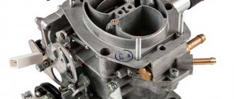
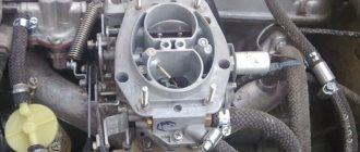
This is what the carburetor installed on a GAZ 53 looks like
The GAZ-53 is equipped with a K-135 carburetor. The carburetor has a balanced float chamber. It is capable of simultaneously opening the throttle valves.
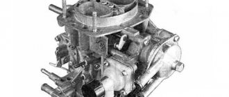
The carburetor was originally brand K126B, and its subsequent modification was K135 (K135M). Fundamentally, the models are almost no different, only the control scheme of the device has changed, and on the latest releases a convenient viewing window was removed from the float chamber. Now it has become impossible to see the gasoline level.
Adjusting the GAZ-53 carburetor
The GAZ 53 carburetor has a two-chamber system, each of which operates on 4 cylinders.
The throttle valve is equipped with a drive for both chambers at once, so fuel is dosed synchronously to all cylinders. To ensure rational fuel consumption at different engine modes, the carburetor is equipped with several systems for regulating the composition of the fuel mixture (FM). This is what the carburetor installed on a GAZ 53 looks like
The carburetor was originally brand K126B, and its subsequent modification was K135 (K135M). Fundamentally, the models are almost no different, only the control scheme of the device has changed, and on the latest releases a convenient viewing window was removed from the float chamber. Now it has become impossible to see the gasoline level.
Search
The GAZ 53 carburetor has a two-chamber system, each of which operates on 4 cylinders. The throttle is equipped with a drive directly into both chambers, so fuel is dosed simultaneously into all cylinders. For optimal fuel consumption in various engine modes, the carburetor is equipped with several carburetor composition control systems.
This is what the carburetor looks like installed on a GAZ 53
Initially, the carburetor was brand K126B, its subsequent modification was K135 (K135M). In principle, the models are practically the same, only the device control circuit has changed, and in the latest releases a convenient viewing window has been removed from the float chamber. Now it is impossible to see the level of gasoline.
K-135 is emulsified, has 2 chambers and a downward flow.
The two chambers are independent of each other, due to which the fuel mixture is supplied to the cylinders through the inlet pipe. One chamber serves from 1st to 4th cylinders, and the other for the rest.
The air damper is located inside the float chamber and is equipped with two automatic valves. The main systems used in the carburetor work on the principle of air braking with gasoline, not counting the economizer.
In addition, each chamber has its own idle system, main dosing system and sprayers. In the 2 chambers of the carburetor, only the steep start system is extended, the accelerator pump, partially the economizer, which has one valve for two chambers, also has a drive mechanism. Separately, nozzles located in the atomizer block and connected to the economizer are installed on them.
Any individual system contains jets of fuel and air and two holes in the mixing chamber. A rubber ring screw is installed in the bottom hole. The screw is designed to control the composition of the flammable mixture. And the rubber seal prevents air from leaking through the screw hole.
You may also like
Carburetor K126BG with gas mixture mixer for passenger cars GAZ 3307 (Gaz 53)
The air stream, in turn, plays the role of emulsifying gasoline.
The idle system cannot provide adequate fuel flow for all engine operating modes, so in addition to it, the carburetor has a basic metering system, which consists of diffusers: large and small, fuel and air injectors and an emulsified tube.
The basis of the carburetor is the main metering system (abbreviated GDS). It ensures a constant composition of the car and does not allow it to be weaker or richer at average speeds of the gasoline engine (ICE). One fuel and one air injector are installed in each of the system chambers.
A little about adjusting the K-135
Adjusting and tuning the carburetor on an oka car.
Adjusting the K-135 on a GAZ-53 when the economizer is turned on must be done with the float chamber covers and gasket removed. By pressing your finger, the bar will be installed so that the distance between it and the float chamber is no less than 14.8 and no more than 15.2 mm.
Also, when adjusting, be sure to press back the adjusting nut so that there is a gap between it and the float chamber within 2.8 - 3.2 mm
You should also pay attention to the operation of the accelerator pump. Its adjustment involves measuring performance, which should be no less than 12 cm3 per 10 full piston strokes
The pump itself should work without jamming. Its sensitivity is also important, which means that the fuel supply must occur simultaneously with the throttle valves starting to operate. Here a delay of no more than 5° is allowed. If the delay is much greater, it means wear - in this case, select a new piston for the accelerator pump well or replace the rubber piston seal.
What if the performance during testing turned out to be much less? This means that the valves are not seated tightly or the atomizer is simply clogged. The problem in this case can be solved by simply blowing or wiping these parts.
If you follow all the above recommendations, the carburetor will work like a Swiss watch.
Adjustment needle
Adjusting the VAZ 2105 carburetor. VAZ 2105 carburetor step-by-step instructions for setting it up. VAZ 2105 carburetor ignition adjustment
The adjusting needle 13 can close the hole connecting the cavity of the float chamber with the cavity of the compensation well.
The idle adjustment needle 4 allows you to change the cross-section of the hole for the passage of air into the cavity 5 and thereby change the quality of the emulsion.
| Direct acting valve block. |
The throttle adjustment needle / / allows you to change the amount of compressed air supplied to the space above the piston 9, and thereby achieve precise adjustment of the valves. This needle allows you to change the switch’s own shutdown time within certain limits.
The adjusting needle of the main jet in carburetors K-22 A and K-49 A should be turned out from its full closing position by no more than 21/-2 g/2 turns.
The adjusting needle of carburetors K-22 A, K-22 G is screwed into the body by hand. When the needles are completely closed, there should be a gap of at least 0 8 mm between the needle handle and the oil seal nut.
The end of the adjusting needle has a thumb (or slot for a screwdriver) located on the outer part of the relay.
The optimal setting of the main jet adjustment needle is made depending on the ambient temperature, road conditions, the quality of the fuel used, the technical condition of the vehicle and its operating conditions. To obtain the greatest engine power (power adjustment of the carburetor), the adjusting needle should be open by approximately 2 5 turns (K-22 G), and to obtain the greatest efficiency (economic adjustment of the carburetor) - by 1 5 turns. When operating the vehicle on good roads, where maximum traction force is not required, the needle should be set to the economic adjustment position.
The diagram shows an adjusting needle that changes the cross-section of the main jet.
By screwing in or out the adjusting needle of the throttle 7, you can change the time of filling the additional reservoir 8 with compressed air, and therefore the beginning of movement of both the piston itself and the block contacts connected to it. When the circuit of block contacts is opened, the power supply to the switching electromagnet is stopped, its core returns to its original position and the switching valve closes, stopping the supply of compressed air to turn on the switch.
The main jet adjusting needle is turned out more than necessary.
In carburetors equipped with an adjusting needle under the main jet (the first editions of MKZ-6, K-49, K-22 and their various modifications), you can slightly lean the mixture without changing the metering holes of the jets
The adjusting needle should be used very carefully, so that there is no backfire into the carburetor and the car’s throttle response does not deteriorate. The carburetor needle K-49 and K-49 A (GAZ-51 car) and K-22 (M-20 Pobeda car), when working on standard motor gasoline, should be unscrewed 21 / 4 l / 8 turns after it was screwed up to failure, carburetor needle K-22 A (M-20 Pobeda car) - at I3 4iV8 revolutions.
An increase in pressure release is achieved by screwing in the adjusting needle, a decrease is achieved by unscrewing it by 0 5 - 1 turn.
| Stove burner. |
The nozzle has a nozzle and a conical adjustment needle at the end, which closes the calibrated hole of the nozzle.
Models of carburetors that were installed on the UAZ-452
The design and principle of operation of the carburetor
“Loaves” from the first day of their production were equipped with carburetors of the K-126, K-129 types and their modifications. This continued until 1985, when the car was completely modernized. Simultaneously with the new, more powerful engines, the UAZ-452 began to be equipped with K-131 and K-151 carburetors, as well as their numerous improved versions.
But the simplest, most reliable and repairable of them turned out to be the K-126 carburetor, which, among other things, was the most economical. If an engine with K-131 and K-151 consumed an average of 15–17 liters of gasoline per hundred kilometers, then the K-126 allowed saving 3–4 liters. All latest models of UAZ-452 carburetors are interchangeable, except that the K-126 requires an additional gasket between its “fifth” and the intake pipe.
The K-126 line is a generation of carburetors produced (Leningrad), which later became the famous “Pekar”. The first models of two-chamber K-126 were manufactured in 1964 for the new ZMZ-53 engine, which replaced the obsolete GAZ-51.
K-126G carburetors are reliable and economical
Engine
The manufacturer equipped this truck with different engines over the years. Thus, the debut versions, which were produced by the plant until 1967, were equipped with six-cylinder GAZ-11 units. This engine produced 82 horsepower and was capable of accelerating the truck to a maximum of 74 kilometers per hour.
Then, after the first restyling or modernization, as they said then, the Soviet truck again received a six-cylinder ZMZ-53 engine. Its nameplate power was as much as 115 horsepower. This made it possible to significantly increase the maximum speed, as well as the load capacity. The engine used two valves per cylinder. Then in 1983-1992.
The GAZ-53 car began to be equipped with the eight-cylinder power unit GAZ-53-12. Its power was 120 horsepower.
Along with these engines, some copies and modifications were equipped with other engines. Thus, we can highlight a 4.25-liter V8 engine with a power of 125 horsepower. Many cars that have survived to this day are equipped with a ZMZ-53 diesel V8.
The unit is distinguished by an aluminum head and cylinder block. The engine is known for its weak elements - the ignition system distributor and the coil often failed.
But in general, the engine could be used for quite a long time - before major repairs, the average mileage was 200 thousand kilometers. The unit was also distinguished by its gluttony - the consumption was serious.
Also, drivers periodically had to do maintenance. The disease of this engine is the GAZ-53 valve. Adjusting them was a common task during routine maintenance.
Transmission
The engines were paired with a four-speed manual transmission. It had four forward gears, as well as one reverse gear. These boxes have also survived to this day, although in some places they were used in rather difficult conditions.
As for other elements in the transmission system of this car, it is built on the basis of a standard scheme. The car is rear-wheel drive, and the clutch is the most classic. Engineers have provided for the possibility of installing a transfer case that could provide power take-off from the engine.
Carburetor
Now a little about the power system. The carburetor on the GAZ-53 is a two-chamber, emulsion carburetor. Its peculiarity is the simultaneous opening of both dampers, while the float chamber is quite balanced. This carburetor has the index K-135.
It, if you compare it with other models, is distinguished by the presence of some adjustments. If configured incorrectly or not configured at all, then it will not be possible to operate it on engines equipped with standard cylinder heads.
The GAZ-53 carburetor works as follows - the first chamber is responsible for supplying the fuel mixture to cylinders 5, 6, 7, 8. And the second one is at 1, 2, 3, 4.
Why adjust valves?
In order for the internal combustion engine to function properly, each cylinder of the engine has an intake and exhaust valve. As the engine heats up, all its elements become hot. This also applies to valves. From the physics course we know that when heated, parts made of any materials expand.
If the valve does not have sufficient thermal clearance, the motor will operate unstably. If you operate an engine with unadjusted valve clearance, it will not develop its full power. At the same time, fuel consumption will increase significantly.
You will also hear characteristic popping sounds in the carburetor and exhaust pipe.
Large gaps create certain difficulties when starting the engine. When you manage to start the unit, you can hear the characteristic knocking sounds of valves and their pushers. When these knocks are heard, urgent adjustment of the GAZ-53 valve is necessary. But you shouldn’t focus only on noise. It is best to adjust the thermal gap in a timely manner. This will allow the motor to work as smoothly as possible.
How are valves adjusted on a GAZ-53? Settings can be done in two ways. Let's look at both. The whole process is extremely simple for those who know a little about cars. You only need to adjust the valves on a cold engine - when the engine is well warmed up, there may be no thermal gaps in it at all. This needs to be taken into account.
Method No. 1
To begin adjusting the valve on the GAZ-53, set the piston of the first cylinder to the highest position - this is the position of the top dead center. In this case, the corresponding mark on the pulley must coincide with the same one on the casing. In this position, both the inlet and outlet valve will be closed.
The gaps under the factory data between the rod and the ring on the rocker should be 0.25-0.3 millimeters. This is your passport information. And if the car is used for a long time, these standards will be ineffective. In this case, craftsmen determine the gap by eye. Most owners of these trucks agree that the most optimal clearance for the intake and exhaust valves is 0.4 millimeters.
Next, use a screwdriver to hold the valve adjustment screw and loosen the lock nut. Then the dipstick is inserted into the gap. The adjusting screw is rotated until the gap is normal.
General device
Replacing the carburetor on a VAZ 2107
The K 135 carburetor circuit is quite simple. In fact, it consists of two independent units assembled in one housing and united by a common float chamber. Accordingly, there are two dosing systems. They include a main diffuser, in the narrowing of which a fuel atomizer is located. Below there is a mixing chamber, the output of the mixture from which is regulated by a gas damper.
The dampers have a common axis, which ensures almost the same volume of air passing through the carburetor chambers. The axis of the dampers is connected by rods to the accelerator pedal of the car.
The metering system provides fuel supply in proportion to the supplied air. The key element of the system is a diffuser with a narrow channel. When air passes through it, a reduced pressure is created, depending on the speed of the flow. Due to this phenomenon, fuel is drawn through the main fuel nozzle from the float chamber. Access to these jets is possible without disassembling the carburetor and is through screw plugs in the float chamber housing.
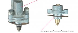
The fuel level is automatically adjusted by a needle valve and an associated float. On older models of carburetors there was a control window in the chamber wall. To maintain the mixture composition, the K 135 carburetor is equipped with a compensation system with air fuel braking.
At low speeds, the air flow is low and there is a lack of vacuum in the metering unit. To ensure engine operation in this mode, an idle system is used.
For the most complete realization of engine power and dynamic acceleration, the K 135 carburetor is equipped with an economizer and an accelerator pump. Among the additional systems, it is worth noting the starting device and the engine speed limiter.
Design and purpose of the carburetor for 135
The Gas-53 carburetor consists of several parts. Fuel consumption is controlled by independent fuel mixture control systems. Characteristics of the gas 53 carburetor has a two-chamber drive for synchronous distribution of the combustible mixture. The modification and design of the carburetor for 135 is equipped with a balanced type float chamber, this makes it possible to simultaneously open the dampers.
Diagram of the K-135 carburetor and speed limiter sensor: 1 - accelerator pump: 2 - float chamber cover; 3 — air jet of the main system; 4 — small diffuser; 5 — idle fuel jet; 6 — air damper; 7 — accelerator pump nozzle; 8 — calibrated economizer sprayer; 9 — discharge valve; 10 — idle air jet; 11 — fuel supply valve; 12— mesh filter; 13 - float; 14 — sensor valve; 15 - spring; 16 — sensor rotor; 17 — adjustment wing; 18 — viewing window; 19 - plug; 20 - diaphragm; 21 — limiter spring; 22 — throttle valve axis; 23 — limiter vacuum jet; 24 - gasket; 25 — restrictor air jet; 26 — cuff; 27 - main jet; 28 - emulsion tube; 29 — throttle valve; 30 — idle speed adjustment screw; 31 — mixing chamber housing; 32 — bearings; 33 — throttle valve drive lever; 34 — check valve of the accelerator pump; 35 — float chamber body; 36 — economizer valve.
This is interesting: Step-by-step instructions for installing fender liner
Thanks to the improved intake, it was possible to achieve a more homogeneous working mixture. A new cylinder head, paired with a manifold, with high-quality tuning, leads to a reduction in toxicity. The carburetor for 135 is equipped with helical channel walls, with an increased compression ratio, allowing you to save up to 7% of fuel.
Main dosing system
The uniform, constant composition of the working fuel mixture is ensured by the main dosing system. The characteristics imply the installation of fuel and air jets on each chamber; the gas 53 carburetor contains an air atomizer as part of the dosing system. The constant composition of the mixture ensures stable operation at medium speeds of the car.
Parameters of the metering elements of the K-135 carburetor
Idle system
Stable and uniform idle speed on a gas carburetor is achieved by the position of the throttle valve. The fuel mixture enters the working part when bypassing the gas pump; the flap for unhindered access to the cylinders must be slightly open in the correct position.
Diagram of the K 135 idle system: 1 - float chamber with a float mechanism; 2 - main fuel jet; 3 - emulsion well with emulsion tube; 4 — “quality” screw; 5—via hole; 6 — fuel supply valve to the idle system openings; 7 — idle air jet; 8 air jet plug; 9 — idle fuel jet; 10 — inlet air pipe.
The design of the carburetor for 135 provides for adjustment of the XX system. The setting directly affects fuel consumption; the quality and quantity screws adjust the mixture supply parameters.
Float chamber
The elements of the float chamber are:
- A locking mechanism, the needle with a membrane of which is installed in the valve seat;
- A float that regulates the amount of fuel mixture in the chambers.
Scheme for checking the fuel level in the carburetor float chamber for 135: 1 - fitting; 2 — rubber tube; 3 - glass tube.
The main purpose of the carburetor float chamber for 135 is to maintain the fuel level for stable operation of the car. The chamber is installed in the main body of the carburetor.
Economizer
The economizer is responsible for realizing the full engine power. The device includes a valve that supplies fuel through channels, bypassing the GDS.
Carburetor economizer for 135
The gas 53 carburetor is designed in accordance with toxicity standards; at stable loads, access to the combustion chamber is blocked from excess fuel.
Acceleration pump
Scheme of the carburetor accelerating pump: 1 - rod; 2 — bar; 3 - well; 4 - spring; 5 - piston; 6 - check valve; 7 - traction; 8 — lever; 9 — throttle valve; 10 - discharge valve; 11 - sprayer.
When you press the accelerator all the way while driving, the accelerator pump built into the carburetor of the 135 model takes over. Fuel is supplied to the 135 by a piston in a cylindrical channel, which begins to enrich the mixture. The device is made with a mixture sprayer, due to this, the car picks up speed smoothly, without jerking.
Speed limiter
The system operates on pneumatics, the movement of the diaphragm occurs due to vacuum, turning the axis of the throttle valves. Mechanically connected to the limiter, the gas 53 carburetor system does not allow the throttle valves to open completely. The engine speed is controlled by the throttle.
Starting system
A cooled engine is started by the starting system. The process goes like this:
- The choke drive lever, attached to the car interior, is pulled out to the required distance;
- The lever system slightly opens the throttle of the air damper drive, thereby shutting off the air.
The launch is carried out by enriching the mixture and controlling the fuel supply. The characteristics of the K135 device are designed in such a way that the car engine does not stall. The air damper has a valve, under the influence of vacuum, which opens air to prevent an overly rich mixture.
Existing insertion methods
For each car model, appropriate gas equipment is selected. Inserting an LPG into a second-generation carburetor is no different from the first LPG. The master selects the best option individually, taking into account the design of the machine.
The simplest option is to install a spacer mixer equipped with a separator. Inserting gas into the carburetor in this way has the main advantages:
- the carburetor body is not subject to mechanical stress;
- there is no drilling process.
This option is often used for inserting gas fittings in carburetors, such as “Ozone”. To do this, remove the textolite gasket and install a gas mixer. This technological operation can be performed on any conventional carburetor.
The installed gas mixer is equipped with a power register. The design provides two outputs, with the possibility of autonomous adjustment. Thanks to the register, you can set the optimal gas supply. This allows you to significantly reduce gas consumption and obtain the best dynamic characteristics. Simple installation has made this method highly popular.
Starting system
The starting system ensures smooth operation of a cool engine. The system consists of pneumatic valves located in the air damper and a system of levers that connect the throttle and air damper. When the choke cable is pulled, the air damper is locked, the rods pull the throttle along with them and open it slightly.
When starting a cool engine, the 53 gas valves in the air damper open under the influence of vacuum and add air to the carburetor, preventing the engine from stalling at a very rich consistency.
Carburetor K-126G, K-126-GM of the Volga car
The K-126G carburetor (Fig. 1 and 2) is a two-chamber carburetor with a falling flow, sequential opening of the throttle valves and a balanced float chamber. The carburetor has two mixing chambers: the primary one operates in all engine operating modes, the second one comes into operation under heavy loads (after approximately 2/3 of the throttle stroke of the primary chamber). The carburetor has a device for unbalancing the float chamber when the throttle valve of the primary chamber is closed. The float chamber housing has a window for monitoring the fuel level. The carburetor is unpretentious in operation, resistant to clogging and poor fuel quality, and has excellent efficiency characteristics (if properly maintained). The main disadvantage is warping of the housing due to overheating and over-tightening of threaded connections. The K-126G carburetor, despite its similarity, differs from its “successor” K-126GM in jet ratings and other features, so you should carefully look at the jet ratings when replacing (See Tables 1 and 2)
All jet channels are equipped with plugs to provide access to the jets without disassembling the carburetor. The main carburetor systems operate on the principle of pneumatic (air) fuel braking. The economizer system works without braking like a simple carburetor. The secondary chamber throttle valve drive is shown in Figure 3.
The carburetor Fig. 4 is controlled using a pedal connected by a system of rods and levers to the carburetor throttle valve and a button placed on the instrument panel and connected by a flexible rod to the air damper.
The air filter (Fig. 5) is an inertial oil filter, with a contact filter element, attached using a clamp and a screw to a bracket mounted on the cylinder head. The filter housing, adapter box and filter element are not dismountable. The filter bath is filled with 0.45 liters of engine oil.
Table 1. Basic adjustment (calibration) data of the K-126G carburetor (for control)
Design features of the K-126 model
The carburetor of the K-126 model of the GAZ-53 is a two-chamber part with a descending flow of the combustible mixture. It also has a mechanically driven economizer with an accelerator pump.
Its body consists of an upper, middle and lower part, each of which is connected with screws, and fuel will flow into the float chamber through a strainer. As a starting device, the K-126 carburetor has an air damper - it has an air valve, which is designed to prevent the formation of an enriched mixture at the moment when the engine starts. And each of the two cameras has its own autonomous idle system.
Features of the modernized engine
The K 135 carburetor (like the K 126) has two chambers, each of which provides 4 cylinders with a working mixture. On older versions of engines there was an intake manifold with intersecting channels at different levels. The first chamber fed cylinders 1, 4, 6 and 7, the second – 5, 2, 3 and 8. The carburetor compartments worked in accordance with the order of flashes in the engine parts. The old type collector is pictured below.
On the modernized engine, the manifold was simplified, and each chamber began to be responsible for the cylinders of its own block. This solution reduced the cost of the collector. But uneven pressure pulsations arose in the chambers of the K 135 carburetor. Due to such pulsations, a scatter in the characteristics of the mixture occurs in different cylinders and at different moments of engine operation. The new collector can be seen in the photo.
But thanks to the new jets, it was still possible to improve the toxicity standards of GAZ 53 engines. The K 135 carburetor ensured the preparation of leaner working mixtures, which slightly smoothed out the heterogeneity of the mixture. A new manifold and carburetor, along with new cylinder heads with an increased compression ratio and helical intake port walls, improved the engines' fuel efficiency by 6-7%. At the same time, the requirements for the octane number of gasoline have not changed.
Float chamber
This is a closed container filled with gasoline to a certain level (2–8 mm below the edge of the spray nozzle). Inside there is a float (13) with a shut-off needle that locks the fuel supply valve (11). When the gasoline level decreases, the float and needle drop and gasoline enters the chamber. As the float is filled, it floats up and the needle closes the fuel channel. To control the level, a line is drawn corresponding to the normal level of gasoline. It is located on the wall of the float chamber or on the window, if available. If adjustment is necessary, remove the chamber cover and gently bend the float tongue: towards the needle - to lower the level, in the opposite direction - to increase.
Solex carburetor
There is the possibility of inserting a gas fitting into the carburetor for installing LPG, which has a separate adjustment. The second generation gas equipment is installed on Solex. This option is much more complicated. However, according to professionals, it is the best for installing gas equipment.
To adjust the fuel supply, there is a special regulator that provides autonomous gas supply to the chambers. The method of inserting gas into a Solex carburetor is considered the most complex, but very profitable. This option can be used under one condition. The owner of the car will never remove gas equipment. Otherwise, it will be necessary to plug the embedded fitting.
How to insert a fitting into a Solex correctly? To perform such a technological operation, you must adhere to a certain sequence:
- The carburetor is being dismantled;
- two holes are drilled in the chamber, and the most convenient place is chosen so that it is easy to connect and secure the gas tubes;
- the thread is cut with a tap;
- screw in the corresponding fittings;
- install and fix gas pipes.
The technological operation of inserting gas into a Solex carburetor must be performed with absolute precision. Such equipment is much easier to configure
It is very important that all parts included in the LPG kit are of high quality and produced by a well-known manufacturer. Assembly and installation should be carried out by a professional technician
Remaking the Solex, when liquid fuel (gasoline) is constantly increasing in price, is completely justified. This is clearly visible when you have to make a large number of different trips by car. The savings are approximately 50%.
Car engine power supply system
Construction machines and equipment, reference book
Category:
1Domestic cars
Car engine power supply system
The purpose of the power supply system is to purify fuel and air, prepare a combustible mixture, supply it to the engine cylinders and remove exhaust gases from them.
Maintenance of carburetors consists of the following operations: - systematic cleaning, flushing and purge of clogged jets; — checking and adjusting the fuel level in the float chamber; — adjusting the carburetor to low engine idle speed; — checking and adjusting the performance of the accelerator pump; — adjustment of the throttle and air damper drive.
The carburetor body is washed in kerosene, and the jets, sprayers, diffusers, economizer valve, float chamber shut-off valve, accelerator pump are washed in acetone, white spirit (they remove tarry deposits).
Clogged jets and nozzles are blown out with compressed air from a compressor or pump. Purge is carried out in the direction opposite to the flow of fuel.
To check and adjust the fuel level in the fuel chamber of the K-88A carburetor installed on a ZIL-130 vehicle, it is necessary to unscrew the plug that closes the economizer valve channel. In its place, screw in an adapter with a transparent tube placed on it, on which two marks are applied, indicating the limits of fluctuations in the fuel level (Fig. 0). The tube is located along the axis of the carburetor. Using the manual pump lever, fuel is pumped into the carburetor float chamber. The fuel level is adjusted by changing the thickness of the gaskets under the needle valve body or by bending the float bracket.
Rice. 0. Checking the fuel level in the float chamber using a glass tube
Rice. 1. Checking and adjusting the fuel level in the float chamber of the K-126B carburetor: 1 - window; 2 - tongue
In the K-126B carburetor installed on the GAZ-53A engine, the fuel level is controlled through an inspection window (Fig. 1). The fuel level in the float chamber is adjusted by bending the tongue on the float lever.
Adjusting the carburetor to low idle speed is done on a warm engine. The stop screw is turned 2 turns, and the mixture quality adjustment screws are turned all the way, then turned 3 turns. The thrust screw is set to a position at which the crankshaft speed becomes minimally stable.
One of the quality screws is smoothly tightened until interruptions in engine operation occur, then unscrew it 1-2 turns. The same operations are carried out with the second quality screw (Fig. 12). Then, by rotating the throttle valve thrust screw, reduce the crankshaft speed to the minimum possible and again repeat the operations of installing the two mixture quality adjustment screws and the thrust screw, thereby achieving the minimum stable speed. The quality of adjustment is checked by sharply opening and closing the throttle valve. The engine should not stop.
Checking and adjusting the operation of the accelerator pump is carried out by measuring its performance, which should be at least 12 cm3 of fuel per 10 piston strokes. The fuel flowing from the carburetor must flow into a measuring beaker. The swing rate is 20 full swings per minute. The accelerator pump should operate smoothly and without jamming.
If the performance of the accelerator pump is less than the specified one, it means that the valves (return and discharge) are leaking or the sprayer is clogged. This can be eliminated by washing and blowing out the nozzle and valve seats.
The angle of the throttle valves is adjusted with the air damper closed as follows.
There is a movable bar on the accelerator pump drive lever, which is attached to it with a screw; The protrusion of the air damper drive lever rests against it. The throttle opening angle should be 12°. To adjust, it is necessary to close the air damper, then, moving the bar, open the throttle valves slightly so that the gap between the edge of the throttle valve and the wall of the mixing chamber is 1.2 mm, which will correspond to the opening angle of the valve. After this, the bar is secured with a screw. Caring for the throttle and air damper drives involves periodically cleaning and lubricating the metal hinges and rods.
Rice. 2. Adjusting the carburetor to low idle speed: a - single-chamber carburetor; b - two-chamber carburetor; 1 — throttle valve thrust screw, 2 — mixture quality adjustment screws
Rice. 3. Adjusting the opening angle of the throttle valves with the air damper closed: 1 - throttle lever; 2 - traction; 3 — adjustment bar; 4 — accelerator pump drive lever; 5 — air damper drive lever; 6 - air damper axis
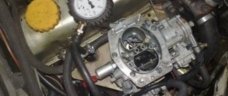
When using a fuel pump, it is necessary to periodically wash the strainer in clean unleaded gasoline. In order to check the pressure created by the pump, you should connect a pressure gauge using a tee and tube to the fuel line going to the carburetor and start the engine. When the engine is running at low idle speed, the pressure gauge readings must comply with the manufacturer's requirements (excess pressure from 0.2 to 0.3 kg/cm2 for different types of pumps). If the pressure created by the pump is below normal, you should check the fastening and serviceability of the pump parts.
Rice. 4. Position of the fuel mixture heating damper during manual adjustment: a - winter; b - summer
The most likely fuel pump malfunctions include damaged diaphragm and leaking valves. Damage to the diaphragm can be detected by fuel leakage through the inspection hole in the housing. Leaking valves leads to a drop in pump performance, as does damage to the diaphragm, but is not accompanied by fuel leakage through the control hole.
Caring for the air purifier involves periodically cleaning and changing the oil in it. The frequency of changing the oil and cleaning the air cleaner depends on the operating conditions of the vehicle. If the air is very dusty in summer, the oil in the air purifier should be changed daily. It is necessary to periodically drain sediment from the sedimentation filter.
The air cleaner filter element and the sump filter housing require periodic washing in gasoline or kerosene during vehicle operation.
Heating the combustible mixture in winter promotes mixing of fuel with air, better distribution of it among the cylinders and evaporation. Heating is carried out manually or automatically. The degree of heating of the mixture in the engine of the GAZ-24 Volga car can be adjusted manually using a movable damper installed in the middle part inside the exhaust pipe. The sector positions for various operating conditions are shown in Fig. 4.
Moskvich car engines have heating of the combustible liquid mixture (carried out by the heat of the coolant).
In order for the diesel engine power system to operate normally, it is necessary to monitor the cleanliness of the fuel and the tightness of the lines. With the fuel, debris gets into the pump, causing increased wear and sometimes scuffing of parts. Therefore, fuel filters, booster pump and injectors, and high-pressure fuel pump must be serviced.
Caring for fuel filters involves periodically washing them with clean diesel fuel and blowing them with compressed air. In the case when the fine filter element is softened and the coarse filter element is very dirty, they must be replaced.
If air has entered the system, it must be removed; to do this, with the engine running, unscrew the plug on the cover of the fine fuel filter. When the release of air bubbles with escaping fuel stops, tighten the plug. The line between the fuel filter and the high-pressure pump, as well as in the channels of the pump head, is checked as follows: unscrew the plug on the pump head and, after the release of air bubbles has stopped, screw it back. If the release of air bubbles does not stop, then the tightness of the line is broken. In this case, you need to check the tightness and, if fuel leaks are detected, tighten all connections.
The fuel priming pump is checked as follows: start the engine and at an engine crankshaft speed of 1200 rpm, disconnect the drain pipeline. Within 1 minute, 1.2-1.5 liters of fuel should flow into the measuring cup. If less fuel leaks out, the fuel priming pump is faulty.
To determine whether an injector is faulty, it is necessary to loosen the nut at the fitting of the injector being tested (so that no fuel enters it), and if the opacity of the exhaust gases has decreased and the crankshaft speed has not changed, then the faulty injector is turned off.
Adjustment of the minimum idle speed of the crankshaft is carried out on a warm engine, for which the lever (Fig. 5) is moved all the way to the bolt of the minimum speed limiter, the lock nut is loosened and the buffer spring housing is unscrewed by 2-3 mm; the bolt of the crankshaft minimum speed limiter is turned out until interruptions in engine operation occur; then the buffer spring housing is gradually screwed in until the interruptions disappear.
You can check the correctness of the adjustment by smoothly increasing the number of revolutions of the engine crankshaft and abruptly resetting them. If the engine does not stall, then the adjustment has been made correctly.
The maximum engine speed is regulated by a bolt.
Air filter maintenance involves promptly washing the filter element in diesel fuel or gasoline. After washing the filter oil bath, oil is poured into it (the same as for the engine) to the mark that determines the normal level. You can use filtered used engine oil. The air filter is then installed on the connecting pipe of the intake pipes and secured with a rod, which is carefully tightened.
Before starting work, you must check the tightness of the air filter mounting rod. Air filter maintenance in conditions of low dust content is carried out through TO-1, and when working in dusty conditions - more often.
Rice. 5. Adjustment of all modes of the speed controller
Read more: Car clutch
Category: - 1Domestic cars
Home → Directory → Articles → Forum
stroy-technics.ru
Gas 53 » power system » carburetor disassembly
Unscrew and remove one end of the low-speed rod from the lever hole, unscrew the seven screws securing the float chamber cover, remove the cover and the gasket under it, being careful not to damage the gasket, remove the float axis and remove the float. Take out the fuel valve needle, unscrew the fuel valve body together with the paronite gasket.
It is not recommended to remove the air damper unless necessary (the gaps between the wall of the air pipe and the damper do not exceed the norm). To remove the damper, unscrew the two screws securing it, remove the damper, then unscrew the screw securing the drive lever bushing, and remove with a growl!' along with bushing and spring. Remove the air damper axle assembly with the lever and return spring.
Unscrew the filter plug, release the paronite gasket and remove the mesh filter.
Unscrew the clamping screw of the accelerator pump and economizer drive fork and remove the drive axis together with the drive lever from the bosses of the float chamber cover. Next, disassemble the body of the float chamber.
Remove the accelerator pump drive rod assembly with the piston and economizer drive from the carburetor body, removing the springs from the guide rod. It is not recommended to disassemble the accelerator pump drive. If it is necessary to replace the accelerator pump piston or for other reasons, unscrew the installation nuts of the accelerator pump and economizer rods and remove the rods by removing the springs.
Unscrew the plugs from the outside of the housing, remove the main fuel jets and idle air jets of both chambers. To access the emulsion tubes, unscrew the main air jets and remove them.
Unscrew the idle fuel jets and the economizer valve. After unscrewing the fuel supply screw, remove the accelerator pump and economizer nozzle block along with the gasket. Remove the accelerator pump discharge valve.
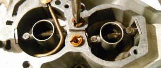
Unscrew the large nut at the front of the housing and carefully, so as not to damage the gasket, remove the sight glass of the float chamber. Small diffusers are not allowed to be pressed out of the carburetor body.
Unscrew the four fastening screws and disconnect the displacement chamber from the float chamber. Take out two large diffusers and the gasket between the chambers.
If necessary, do not disassemble the mixing chamber. If the axis of the throttle valves swings in the bosses or the tightness of the valves to the walls of the chamber is unsatisfactory, and the axial play of the valve in the open state exceeds 0.2 mm, the mixing chamber is disassembled.
To completely disassemble the mixing chamber, unscrew the three screws securing the throttle drive axis housing and remove it along with the gasket. Unscrew the four screws of the housing cover of the speed limiter actuator, remove its gasket and, having unscrewed the three fastening screws and the nut of the double-arm lever of the throttle axis, remove the housing of the actuator.
Remove the spring and the sealing cuff of the right bearing from the mixing chamber housing, unscrewing two fastening screws each, and remove the throttle valves and their axis from the mixing chamber housing. Disconnection of the throttle valves from the mixing chamber is carried out in exceptional cases when it is impossible to eliminate jamming of the valves by washing. In cases of disassembly, the completeness of the throttle valves relative to the chambers is not allowed. Before assembly, all parts must be carefully checked and have no noticeable wear in the connections: float axis - float bracket, float axis - cover posts, throttle axis - mixing chamber housing bosses, piston - accelerator pump well, accelerator pump drive guide rod - bushing float chamber housing.
How can you check the fuel level?
The most important condition for stable operation of the carburetor float is its free movement on the axis, and at the same time, the tightness of the housing is important. Please note that the valve needle must move absolutely freely, without any jamming. And in those cases when they occur, the problem turns out to be a violation of the integrity of the float body - in this case, adjusting the fuel level in the float chamber will be almost impossible.
How to check the tightness of the float? This can be done by opening the carburetor, removing the float and immersing it in hot water. If air bubbles appear on the surface, this will indicate damage. To eliminate the malfunction, a puncture is made in this place and simply remove the remaining water and fuel from the float. After this, all that remains is to dry and solder the hole. Such adjustment of the float operation is impossible without taking into account its weight, which should not exceed 14 g (if it turns out to be more, you need to remove excess solder).
The fuel level in the chamber is adjusted when the GAZ-53 car is standing on a flat horizontal platform. In this case, you should check it with the engine idling - ideally it will be no more than 20.5 mm from the lower edge of the connector at the float chamber. If this distance is not maintained, then you simply need to adjust the position of the float (remove the top part of the carburetor and bend the bracket tongue itself at the float in the desired direction). This adjustment must be carried out very carefully, otherwise there is a risk of damaging the sealing washer.
What does it consist of?
Each carburetor has systems that help it function properly under certain conditions. There are also additions that help them function properly (for example, these include solenoids designed to cut off the fuel supply or pressure surge absorbers). It is not recommended to remove such components, as this will have a noticeable effect on engine operation.
So, any carburetor for GAZ-53 will consist of the following parts:
- Float chamber;
- Air damper;
- Idle system;
- Acceleration pump;
- Transition system;
- Main carburetor metering system;
- Economizer.
K-126 carburetor diagram
How to adjust idle speed on K-126?
This procedure should be carried out with the engine warmed up to a temperature of 80 degrees Celsius. It is in this case that the carburetor will show optimal results. Before such an adjustment is carried out, you should pay attention to ensure that all parts of the ignition system are in good condition, and that the clearances necessarily meet the above requirements.
First of all, turn the mixture adjustment screw all the way in and turn it out 2.5 or 3 turns. After this, you need to start the engine and use the thrust screw to set the average speed to approximately 600 rpm.
If the adjustment of the carburetor-126 was carried out correctly, the engine will not stall even when the carburetor damper is sharply opened - on the contrary, it will begin to gain maximum speed.
Diagram of the upper part of the GAZ-53 carburetor
Device
K-135 is emulsified, with two chambers and a falling flow.
The two chambers are independent of each other; through them, the combustible mixture is supplied to the cylinders through the intake pipe. One chamber serves cylinders 1 to 4, and the other serves all the others.
The air damper is located inside the float chamber and is equipped with two automatic valves. The main systems used in the carburetor operate on the principle of air braking of gasoline, except for the economizer.
In addition, each chamber has its own idle system, main dosing system and sprayers. The two carburetor chambers have in common only a cold engine starting system, an accelerator pump, partly an economizer, which has one valve for two chambers, and a drive mechanism. The jets located in the nozzle block and related to the economizer are installed separately on them.
Each idle system includes fuel and air jets, and two holes in the mixing chamber. A screw with a rubber ring is installed on the bottom hole. The screw is designed to regulate the composition of the combustible mixture. And the rubber seal prevents air from penetrating through the screw hole.
The idle system cannot provide the required fuel consumption in all engine operating modes, so in addition to it, a main metering system is installed on the carburetor, which consists of diffusers: large and small, fuel and air jets and an emulsified tube.
Main dosing system
The basis of the carburetor is the main metering system (abbreviated as GDS). It ensures a constant composition of the vehicle and does not allow it to become lean or rich at medium speeds of the internal combustion engine (ICE). Each chamber in the system is equipped with one fuel and one air jet.
Idle system
The idle system is designed to ensure stable operation of the engine at idle speed of the internal combustion engine. The carburetor throttle valve should always be slightly open, and the gasoline mixture at idle speed (idle) enters the intake tract, bypassing the gas pump. The position of the throttle axis is set by the quantity screw, and the quality screws (one for each chamber) allow you to enrich or lean the mixture at idle. The fuel consumption of the vehicle largely depends on the adjustment.
Float chamber
The float chamber is located in the main body and maintains the level of gasoline in the carburetor necessary for the normal operation of the engine power system. The main elements in it are a float and a locking mechanism, consisting of a needle with a membrane and a valve seat.
Economizer
The economizer system enriches the vehicle at high engine speeds with increasing load. The economizer has a valve that, when the throttle valves are opened to maximum, releases a portion of additional fuel through the channels, bypassing the GDS.
Acceleration pump
In the K126 (K135) carburetor, the accelerator is a piston with a cuff that operates in a cylindrical channel. At the moment of sharp pressing of the accelerator (gas) pedal, the throttle valve drive, mechanically connected to the accelerator system, causes the piston to quickly move along the channel.
Diagram of the K126 carburetor with the names of all elements
Speed limiter
The system prevents the crankshaft from exceeding a certain number of revolutions due to incomplete opening of the throttle valve. The operation is based on pneumatics; due to the vacuum, the diaphragm in the pneumatic valve of the device moves, turning the throttle valve axis mechanically connected to the limiter assembly.
Starting system
The starting system ensures stable operation of a cold engine. The system consists of pneumatic valves located in the air damper and a system of levers that connect the throttle and air damper. When the choke cable is pulled, the air damper closes, the rods pull the throttle along with them and open it slightly.
When starting a cold engine, the 53 gas valves in the air damper open under the influence of vacuum and add air to the carburetor, preventing the engine from stalling with a mixture that is too rich.
Operating modes, ideal carburetor characteristics.
The power of internal combustion engines is determined by the energy contained in the fuel and released during combustion. To achieve more or less power, it is necessary, accordingly, to supply more or less fuel to the engine. At the same time, combustion of fuel requires an oxidizer—air. It is the air that is actually sucked into the engine pistons during the intake strokes. By using the gas pedal connected to the carburetor throttle valves, the driver can only limit the access of air to the engine or, on the contrary, allow the engine to fill to the limit. The carburetor, in turn, must automatically monitor the air flow entering the engine and supply a proportional amount of gasoline.
Thus, the throttle valves located at the outlet of the carburetor regulate the amount of the prepared mixture of air and fuel, and therefore the engine load. Full load corresponds to maximum throttle openings and is characterized by the greatest flow of combustible mixture into the cylinders. At "full" throttle, the engine produces the most power achievable at a given speed. For passenger cars, the share of full loads in actual operation is small - about 10...15%. For trucks, on the contrary, full load modes occupy up to 50% of the operating time. The opposite of full load is idle. In relation to a car, this is the operation of the engine with the gearbox turned off, regardless of what the engine speed is. All intermediate modes (from idle to full load) fall under the definition of partial load.
A change in the amount of mixture passing through the carburetor also occurs at a constant throttle position in the event of a change in engine speed (the number of operating cycles per unit time). In general, load and rotation speed determine the operating mode of the engine.
A car engine operates in a huge variety of operating modes caused by changing road conditions or the desire of the driver. Each driving mode requires its own amount of engine power, each operating mode corresponds to a certain air flow and must correspond to a certain mixture composition. Mixture composition refers to the ratio between the amount of air and fuel entering the engine. Theoretically, complete combustion of one kilogram of gasoline will occur if slightly less than 15 kilograms of air are involved. This value is determined by the chemical reactions of combustion and depends on the composition of the fuel itself. However, in real conditions it turns out to be more profitable to maintain the composition of the mixture, although close to the named value, but with deviations in one direction or another. A mixture in which there is less fuel than theoretically required is called lean; in which there is more - rich. For quantitative assessment, it is customary to use the excess air coefficient a, showing the excess air in the mixture:
Carburetor malfunctions
There can be many different malfunctions in the carburetor of a GAZ 53 car, but all of them are associated with increased fuel consumption, regardless of whether the mixture enters the cylinders rich or lean. In addition to increased fuel consumption, the following symptoms of malfunctions are characteristic:
- There is black smoke coming from the exhaust pipe. It is especially noticeable with a sharp increase in engine speed. In this case, shots may be fired into the silencer;
- The engine is unstable at idle and may also stall at idle;
- The engine does not develop speed, chokes, there are pops in the intake manifold;
- With sharp acceleration, a failure occurs in the operation of the internal combustion engine;
- Sluggish acceleration of the car, but at high speeds the car drives normally;
- Lack of power, engine does not develop speed;
- Jerks when moving, especially noticeable when accelerating.
Carburetor repair for GAZ 53 truck
Any of the carburetor systems can be faulty, but most often the following occurs:
- The idle system is clogged. The engine runs unstably at idle and stalls. Gasoline consumption increases significantly;
- The accelerator pump piston is jammed in the cylinder. When accelerating sharply, the car jerks and the carburetor fails;
- Warping of the float chamber housing at the junction with the throttle valve assembly. Air leaks into the connection, the vehicle becomes leaner, and the motor operates unstably. It is very difficult to adjust XX - the carburetor is practically impossible to adjust;
- The GDS jets become clogged - fuel and air. All blockages in the carburetor occur due to a clogged fuel filter or operating the car in dusty conditions. The air filter may also be clogged;
- The float or the locking needle of the float mechanism loses its tightness. The carburetor begins to overflow, and often the car cannot be started at all due to the overflow of gasoline.
Repairing a carburetor first of all involves flushing and purging all systems. To do this, the carburetor is removed and disassembled to clean all the jets.
Malfunctions affecting fuel consumption
Signs
Carburetor malfunctions negatively affect engine performance. Signs of carburetor problems:
- Unstable operation of the internal combustion engine at idle, or the engine regularly stalls at these speeds;
- Dips at medium speeds;
- When you press the accelerator pedal sharply, the engine jerks and choke;
- The internal combustion engine does not develop high speeds;
- Black smoke comes from the muffler pipe;
- Popping noises and shots are heard from the carburetor or exhaust pipe;
- The engine only runs with the choke half closed;
- The engine “troubles” and floods the spark plugs;
- The engine is difficult to start, and only when the gas pedal is pressed.
It should be noted that almost any carburetor malfunction is accompanied by increased fuel consumption.
There is no question of an acceptable standard here, and at such a flow rate the needle of the fuel level sensor in the car is rapidly approaching zero even at a speed of 60 km/h on a flat road.
Possible faults
- The simplest fault that is easily identified is a leaky float in the float chamber. This problem is immediately visible as soon as you open the engine compartment hood. In this case, it smells like gasoline and the entire carburetor is flooded. If the shut-off needle in the float chamber is faulty, then such a defect is not so obvious, but the idle speed can no longer be adjusted.
This is what a carburetor float looks like
In general, there can be many different causes of carburetor malfunctions; it is better to entrust the repair of such a complex device to a good, competent specialist.
Carburetor malfunctions
There can be many different malfunctions in the carburetor of a GAZ 53 car, but all of them are associated with increased fuel consumption, regardless of whether the mixture enters the cylinders rich or lean. In addition to increased fuel consumption, the following symptoms of malfunctions are characteristic:
- There is black smoke coming from the exhaust pipe. It is especially noticeable with a sharp increase in engine speed. In this case, shots may be fired into the silencer;
- The engine is unstable at idle and may also stall at idle;
- The engine does not develop speed, chokes, there are pops in the intake manifold;
- With sharp acceleration, a failure occurs in the operation of the internal combustion engine;
- Sluggish acceleration of the car, but at high speeds the car drives normally;
- Lack of power, engine does not develop speed;
- Jerks when moving, especially noticeable when accelerating.
Carburetor repair for GAZ 53 truck
- The idle system is clogged. The engine runs unstably at idle and stalls. Gasoline consumption increases significantly;
- The accelerator pump piston is jammed in the cylinder. When accelerating sharply, the car jerks and the carburetor fails;
- Warping of the float chamber housing at the junction with the throttle valve assembly. Air leaks into the connection, the vehicle becomes leaner, and the motor operates unstably. It is very difficult to adjust XX - the carburetor is practically impossible to adjust;
- The GDS jets become clogged - fuel and air. All blockages in the carburetor occur due to a clogged fuel filter or operating the car in dusty conditions. The air filter may also be clogged;
- The float or the locking needle of the float mechanism loses its tightness. The carburetor begins to overflow, and often the car cannot be started at all due to the overflow of gasoline.
Repairing a carburetor first of all involves flushing and purging all systems. To do this, the carburetor is removed and disassembled to clean all the jets.
Differences in approach to K-126 and K-151
Adjusting the 4178 carburetor on the UAZ
The basic principles of repair and adjustment are practically the same for both lines of K-151 and K-126 carburetors, with the exception of the specifics of the operation of the pneumatic valve and the K-151 electronic unit. More problems arise when some carb components are incorrectly replaced with spare parts of a different model.
Often, after replacing the K-151 carburetor with the simpler K-126 model, a number of problems arise. First of all, the poor quality of the lower carburetor block leads to the formation of cracks, air leaks and a sharp leaning of the mixture. To prevent breakage, it is necessary to carefully align the mating plane on sandpaper glued to the glass.
In some cases, adjusting and repairing the K-126 carburetor does not make sense at all due to significant wear at the interfaces of mechanical parts, for example, in the support holes of the damper axis or rods, and the threads of the adjusting screws. In such places, leakage and evaporation of gasoline may occur with simultaneous air leakage. They are easily recognized by the icing that has formed on the body of the K-126 carburetor.
Adjustment
The K126B carburetor (also the K135 carburetor) has several adjustments:
- idle move;
- gasoline level in the float chamber;
- piston stroke of the accelerator pump;
- moment when the economizer system is turned on.
Only one adjustment is made without disassembling the carburetor itself - this is idling the engine. This procedure is performed most often; any driver can perform it. It is better to entrust the remaining adjustments to specialists, but there are often craftsmen who make any adjustments with their own hands.
For proper adjustment, the XX engine must be technically sound, all cylinders must work without interruption.
Idle speed adjustment:
- with the engine turned off, tighten the quality screws of both chambers until the end, then unscrew each approximately 3 turns;
- start the engine and warm it up to operating condition;
- use the quantity screw to set the number of revolutions XX to approximately 600. There is no tachometer in the GAZ 53 car, so the revolutions are set by ear - they should not be too low or high;
- we tighten one of the screws for quality and torque until interruptions in the operation of the internal combustion engine appear, then we move the screw back approximately one-eighth of a turn (until stable operation of the engine);
- We do the same with the second camera;
- use the quantity screw to set the required speed;
- If necessary, use the quality screw to increase the speed if the engine stalls when you release the gas pedal.
Adjustment and repair
Carburetor adjustment
Without completely disassembling the device, it is possible to adjust only the idle level with your own hands. Fuel consumption depends directly on the crankshaft speed. The principle of operation involves adjusting the gas carburetor with 53 quality and quantity screws.
There are several adjustments:
- The amount of gasoline in the float chamber;
- Setting up the economizer operation;
- Accelerator pump piston stroke;
- Number of revolutions, idle jet.
Correct idle speed control is carried out on a working engine. Usually the procedure is performed after prophylaxis in order to exclude other possible causes of unstable operation.
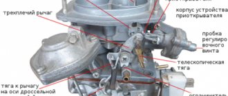
Type of carburetor without cover: 1 economizer rod; 2 drive bracket for echonomizer and accelerator; 3 — accelerator piston; 4 - main air jets; 5 — accelerator pump fuel supply screw; 6 — “quality” screws; 7 — “quantity” screw
The process and scheme for adjusting the idle speed on the 53 carburetor is the following operating principle:
- The adjusting screws of a cold engine are tightened until they stop, then unscrew 3 full turns. It is possible to adjust the carb using a slotted screwdriver;
- Warm up the engine to operating temperature;
- The number of revolutions to 135 is adjusted by ear with a screw, since the car is not equipped with a tachometer. The revolutions should be kept between high and low, weaving and jerking are unacceptable;
- The K135 quality screw is tightened until the level of engine interruptions begins; it is necessary to adjust it gradually, adjust the groove with your own hands, until normal, stable operation is achieved.
- The quantity is adjusted on both chambers, parallel to each other;
- In cases where the car stalls when releasing the gas, it is possible to increase the operating speed.
Repair of the gas 53 carburetor is carried out in case of significant damage to the components or detected contamination. Flushing is carried out on demand; too frequent a procedure can forget the fuel supply channels and damage the devices. The most common method is to clean the float chamber. Deposits are removed only with the top layer, since stuck-on dirt can get into the inlet part of the channels and disrupt the operation of all systems. The causes of soot and deposits are poor quality or old fuel filters. Carburetor gas 53 when flushing, you should immediately replace all fuel and air filters.
During the disassembly process, it is necessary to check the condition of all elements of the system. We will repair jets, dampers and the accelerator pump, which have thin channels that, when clogged, affect engine operation.
Maintenance and possible adjustment of the gas 3307 carburetor installed on a gazelle car does not require complete removal from the engine. The plant has provided that dismantling the air filter makes it possible to routinely check the condition and adjust the idle speed. When completely cleaning and replacing components, the assembly is removed from the engine. Proper technical operation and filter replacement make the need for a complete overhaul minimal. It is enough to carry out preventive maintenance as contamination occurs in the form of flushing the K-135 carburetor.
Flushing is carried out using a flammable liquid. There are special means, the principle of which allows liquid to be delivered under air pressure to hard-to-reach places and grooves. External washing is carried out with a brush until deposits and dirt are completely removed.
Care should be taken when washing internal parts, as there is a possibility of breaking seals or clogging the channels with dirt.
Features of the modernized engine
The K 135 carburetor (like the K 126) has two chambers, each of which provides 4 cylinders with a working mixture. On older versions of engines there was an intake manifold with intersecting channels at different levels. The first chamber fed cylinders 1, 4, 6 and 7, the second – 5, 2, 3 and 8. The carburetor compartments worked in accordance with the order of flashes in the engine parts. The old type collector is pictured below.
On the modernized engine, the manifold was simplified, and each chamber began to be responsible for the cylinders of its own block. This solution reduced the cost of the collector. But uneven pressure pulsations arose in the chambers of the K 135 carburetor. Due to such pulsations, a scatter in the characteristics of the mixture occurs in different cylinders and at different moments of engine operation. The new collector can be seen in the photo.
But thanks to the new jets, it was still possible to improve the toxicity standards of GAZ 53 engines. The K 135 carburetor ensured the preparation of leaner working mixtures, which slightly smoothed out the heterogeneity of the mixture. A new manifold and carburetor, along with new cylinder heads with an increased compression ratio and helical intake port walls, improved the engines' fuel efficiency by 6-7%. At the same time, the requirements for the octane number of gasoline have not changed.
Main dosing system
Designed to prepare the required amount of fuel mixture at medium and high engine speeds. When the throttle valve is fully or partially open, air rushes into the combustion chamber. In a small diffuser (atomizer, 16), the air speed increases and a vacuum is formed. Gasoline is sucked in through the nozzle (11). The dimensions of the holes in the diffusers and nozzles are selected to form an optimal fuel mixture. As engine speed increases, the mixture must be slightly leaner. This is done by the emulsion tube (13), located in the well under the air jet (12).
As the engine speed increases, the vacuum in the emulsion well also increases, and air enters there. Mixed with gasoline, it forms an emulsion and compensates for the increasing vacuum. Less gasoline passes through the nozzle (11), and the mixture becomes leaner.
ZIL Housekeeping Assistant › Logbook › Adjusting and tuning the caburator (carb gas 53).
Hi all! I have such a Gazonovsky carb, visually in the photo, I don’t know the number on the carb itself, level 2 inscriptions, and on the back it was made in Russia. Here’s a problem that seems like a small thing, but at the same time it’s not a small thing. I assembled the motor and now it’s time to tune the motor. I checked the spark plugs, the distributor cap and new wires, the ignition is set. At idle it seems to work cleanly, but you press the gas pedal and it either stalls or revs up a couple of times, it de-accelerates, it doesn’t develop maximum speed, it can’t start normally, the car doesn’t drive, in general it’s a nightmare, I cleaned the carb, you could say by slightly partial disassembling, that is, I removed the top cover, the level is normal , I blew out the jets, it seems to be sulking everywhere. Although before the repair there was no sneezing or coughing, it seemed to be moving normally. Gasoline seems to be normal from GAZPROM. In general, help, tell us what to clean in it, what else can be turned and where not to go. P.S. The issue with the carburetor was resolved, cured by complete disassembly, cleaning with a van + compressor and tuning according to the manual.
Idle system
idle system is designed to ensure smooth operation of the engine at idle speed of the internal combustion engine. Carburetor throttle valve
should always be slightly open, and the gasoline mixture at idle speed (idle) enters the intake tract, bypassing the gas pump.
The position of the throttle axis is set by the quantity screw , and the property screws (one for each chamber) allow you to enrich or lean the mixture at idle. The fuel consumption of the vehicle largely depends on the adjustment.
Carburetor malfunctions
There can be many different malfunctions in the carburetor of a GAZ 53 car, but all of them are associated with increased fuel consumption, regardless of whether the mixture enters the cylinders rich or lean. In addition to increased fuel consumption, the following symptoms of malfunctions are characteristic:
- There is black smoke coming from the exhaust pipe. It is especially noticeable with a sharp increase in engine speed. In this case, shots may be fired into the silencer;
- The engine is unstable at idle and may also stall at idle;
- The engine does not develop speed, chokes, there are pops in the intake manifold;
- With sharp acceleration, a failure occurs in the operation of the internal combustion engine;
- Sluggish acceleration of the car, but at high speeds the car drives normally;
- Lack of power, engine does not develop speed;
- Jerks when moving, especially noticeable when accelerating.
Carburetor repair for GAZ 53 truck
- The idle system is clogged. The engine runs unstably at idle and stalls. Gasoline consumption increases significantly;
- The accelerator pump piston is jammed in the cylinder. When accelerating sharply, the car jerks and the carburetor fails;
- Warping of the float chamber housing at the junction with the throttle valve assembly. Air leaks into the connection, the vehicle becomes leaner, and the motor operates unstably. It is very difficult to adjust XX - the carburetor is practically impossible to adjust;
- The GDS jets become clogged - fuel and air. All blockages in the carburetor occur due to a clogged fuel filter or operating the car in dusty conditions. The air filter may also be clogged;
- The float or the locking needle of the float mechanism loses its tightness. The carburetor begins to overflow, and often the car cannot be started at all due to the overflow of gasoline.
Repairing a carburetor first of all involves flushing and purging all systems. To do this, the carburetor is removed and disassembled to clean all the jets.
System operation sequences
The work of each of the above components is a guarantee of excellent performance and the carburetor itself. For example, a float system maintains a constant fuel level in the float chamber. The air damper allows a cold engine to start by enriching the air-fuel mixture. The idle system ensures that the engine flow is provided, which is necessary to operate the engine at low speeds when the metering system is not yet operating. But the accelerator pump is designed to inject additional fuel to prevent stalling and interruptions in the engine during acceleration of the car (usually this happens when the throttle is opened sharply).
Next, it’s up to the transitional system. It is needed to enable the transition mode between idle and operation of the main dosing system. But the latter precisely forms the necessary gas-air fog, that is, the supply of fuel to the engine while the car is moving at average speeds.
And finally, when the engine is running under load, a richer air-fuel mixture is required than in normal operation. It is the economizer system that will provide additional fuel.
Settings
This element of the car is quite simple in design and does not require much attention when used correctly. Adjusting the K 135 carburetor includes adjusting the starting device, monitoring the fuel level in the chamber and adjusting the idle system.
When adjusting the starter, it is necessary to close the air damper, which, through a rod, will move the gas damper to the starting position. The gap between the gas valve and the chamber wall should be within 1.2 mm. Adjusting the device consists of setting this parameter and is performed using an adjustment bar in the damper drive. Easy starting of a cold engine is only possible with the specified clearance.
Another important step in adjusting the K 135 carburetor is setting the fuel level in the float chamber. To do this, measure the distance between the float and the plane of the lid. It should be 40 mm. The measurement is carried out with the cover removed and upside down. The distance is adjusted by bending the valve needle drive tongue. At the same time, it should not have any damage or dents. The final control of the fuel level is carried out on the installed carburetor.
Repair
Disassembly and repair of the K 135 carburetor is carried out if parts are damaged or the device is heavily soiled. However, you should not overuse washing and cleaning. After all, there is a risk of clogging the channels inside the carburetor with dirt and disrupting the worn-in connections.
One of the most common operations is flushing the float chamber. In this case, only easily removable deposits are removed. Dirt that is tightly stuck to the walls should not be cleaned. Deposits in the chamber are a consequence of the poor condition of the fuel filtration system. Therefore, cleaning should be combined with replacing and cleaning filters.
When disassembling the carburetor, you should pay attention to the condition of the jets; if necessary, they should be washed. The condition of the floats (they are of two types - brass and plastic), damper axles, and accelerator pump is checked. All damaged parts should be replaced with new ones.
The condition of the surfaces of the mating parts of the housing is monitored separately. If necessary, they are ground in on a surface plate.
Upon completion of the work, the carburetor is reassembled, adjusted and installed on the engine.
In any car, every detail is important and fulfills its intended role. The carburetor also has such functions. Being a device for dosing fuel and preparing a combustible mixture, it prepares the fuel in the cylinders for more complete combustion. All preparation usually consists of spraying liquid fuel into small drops and evaporating, mixing with air.
In GAZ-53 cars on ZMZ-53 engines, a K-126 and K-135 carburetor is installed. If you compare the same parts that were once equipped with the ZIL-130 and Moskvich-412, you can see that they are very similar. The difference here is obvious in the dimensions and possibilities of its adjustment. This is precisely what determines some of the features that carburetors for the GAZ-53 have.
Types of carburetors K-126