Hi all!
I wondered how to accurately adjust the carburetor, because... after the latest events, I realized that I need to change the repair kit and clean and check everything (before this, as usual, there is a lack of time)
I dug up materials from several sites... let's go
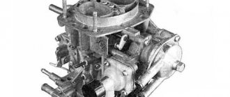
The procedure for setting the fuel level in the float chamber of carburetors 2108, 21081, 21083 Solex
— Place the car on a level surface
— Remove the engine air filter housing
— Let the engine idle for five minutes
— Remove the top part (cover) of the carburetor
— Using a ruler (or better yet, a caliper), measure the distance from the bottom of the float chamber to the level of fuel in it (This must be done as quickly as possible, since gasoline evaporates very quickly)
The required fuel level in Solex carburetors, indicated on most websites, is –24 +- 1 mm from the top edge of the carburetor float chamber. If the measured fuel level differs from the required one, the position of the floats should be adjusted.
Adjusting the float position
— Turn the carburetor cover over and place it on a flat surface
— We measure the distance from the bottom of each of the floats to the cardboard gasket of the lid
The measurement can be carried out with a round probe, a drill, or a piece of wire of the required diameter.
It should be 1-2 mm, which will allow you to achieve the above-mentioned -24 +- 1 mm. If the measured distance does not correspond to the required one, slightly bend the tongue on the float levers (the one that touches the needle valve ball) or the levers themselves and measure again. At the factory, a special template is used for such installation of floats (photo below).
Checking the correct fuel level
Place the carburetor cover vertically. In this case, the tongue on the float levers should recess the damping ball on the needle valve and be approximately parallel to the plane of the needle valve, and the stamping line on the floats should be parallel to the surface of the carburetor cover. If this does not happen, we adjust the fuel level again, more carefully.
Notes and additions
— When adjusting the fuel level in the float chamber of carburetors 2108, 21081, 21083 Solex, you should check the correct position of the floats in the float chamber. To do this, on the carburetor cover removed, inverted and installed horizontally, we ensure that the floats are parallel with respect to the imprint on the cardboard gasket of the cover. This way we will prevent the floats from touching the walls of the float chamber.
— In addition, it is worth setting the amount of free play of the floats. On the inverted lid, use a ruler or caliper to measure the distance from the cardboard spacer to the lower corner of each of the floats.
Raise the floats as high as possible and again measure the distance from the lower corner of the floats to the cardboard spacer. There should be an increase of 15 mm. This is the free movement of the floats. If it does not correspond to the required value, we achieve the required value by bending the rear tongue on the float levers.
P/S/ I also found on the Internet a subjectively correct table for selecting jets (relatively fair, but not a fact) Solex maintenance book on my Yandex storage It’s here Summing up the carb settings, before selling the car I found that from 1.3 the highway consumption was 5.5 l, from 1.5 about 6 speed 90 km/h gearbox 4
One of the most common and common causes of problems with the engine, from which it may simply not work, is an incorrect fuel level in the carburetor float compartment. In this case, it does not matter whether the engine is warmed up or not - an incorrect fuel level will be a hindrance for it. An unexpected malfunction in the car’s engine when pressing the gas pedal is also possible, an increase in the volume of fuel consumed and low power and throttle response of the engine.
To correct the fuel level in a Solex 21083 carburetor yourself, you do not need any extra knowledge or skills. Just a few tools will be enough.
To adjust the fuel level you will need the following tools:
- Measuring tools, such as a regular ruler, or a more advanced version - a caliper;
- Tools for checking the fuel level: a dipstick, a thin drill, or you can get by with a small amount of wire, the main thing is that its diameter does not exceed one millimeter);
- Small pliers;
- Keys.
Preliminary work
Before starting the main work, it is necessary to prepare the working part.
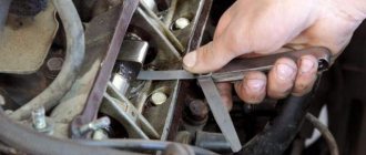
- At the very beginning, the air filter housing is removed. To remove it you need to unscrew the nut that holds the cover from the housing. A ten millimeter wrench will help with this. The cover is held in place by four latches; they will need to be removed. After this, the hose clamp for ventilation is loosened and the hose itself and the filter element are removed. To completely remove the filter housing, all that remains is to unscrew the four nuts (with an 8 mm wrench) that secure it to the carburetor.
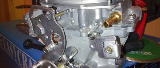
- Next will be the removal of the carburetor cover. To remove it, you need to loosen the clamps on the fuel hoses and then remove these hoses from the carburetor fittings. Remove the wire and unscrew the screws that secure the cover to the body. Then you need to lift the carburetor cover quite a bit. The main thing here is not to touch the chamber walls with the floats.
- The cover must be turned upside down and placed on a flat surface without losing any of the screws that fall out of the cover.
- Check the floats. There must be parallelism between the side surfaces of the floats and between the imprint of the walls of the float chamber. If there is no parallelism, then you need to create it by bringing these same floats together and spreading them apart. As a result: they will be easily located inside the chamber and will not touch its walls.
- Take measurements relative to the cardboard spacer and the protrusion of each float. You need to use a probe, a thin drill, or a wire with a diameter of one millimeter. If the measured distance differs from the required one, it does not matter in which direction: more or less. This indicates that the fuel level in the float chamber is incorrectly set and it is necessary to react to the fuel level again.
↑
How to choose jets?
The selection of jets for Solex 21083 is made taking into account the engine size. Experts recommend starting the selection with a fuel nozzle for the first chamber. Having selected the desired sample, we select the corresponding air analogue for it. And then in the same order we select the jets for the second chamber. First you need to look for a factory carburetor designed for the size of your engine, remove the jets from it and take them as a reference point. Further selection of jets is made according to this principle. If you need to lean the mixture a little, choose a larger jet by one pitch. If you want to enrich it, use a smaller jet.
Emulsion hoses are assembled along with the jets. These tubes are designed to adjust the composition of the fuel mixture in accordance with engine speed. There are three types of tubes: 23, ZC and ZD. The first are used for Solex 21083 carburetors installed on transverse chisel engines. For the first chamber of carburetors of UZAM power units, ZD tubes are used, and for the second - ZC.
Adjusting the fuel level in the Solex carburetor 21083, 2108, 21081
When the carburetor cover is removed, everything should look like this. The approximate fuel depth level should be approximately twenty-nine millimeters plus or minus one millimeter. The level must be measured immediately after the carburetor cap is removed. It is necessary to do this immediately only so that the gasoline does not evaporate. But you need to understand that the numbers given in the article are not an exact number, they are just an average value.
Sometimes those who repair cars use conditional values in order to correctly set the fuel level. Such repairmen spontaneously control the tongue located on the float lever. They also sometimes pump up fuel to achieve the optimal level in the float chamber.
However, they are not guided by anything to do these actions. This approach has its place, but in order to achieve more accurate and accurate results, it is necessary to perform the usual standard fuel adjustment. At a minimum, standard adjustment is recommended by factories, and no special skills are required to carry it out. This adjustment is carried out in two simple steps on the carburetor cover turned upside down and positioned horizontally.
Adjustment, adjustment and cleaning
It is very undesirable to make changes to the calibration of the Solex carburetor, since this is a very accurate and balanced device with well-chosen characteristics.
All adjustments are of an operational nature and rarely change, but they must be checked preventively and adjusted if necessary:
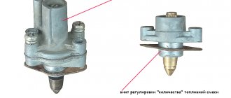
- Adjusting the composition of the idle mixture is carried out using a gas analyzer, since the carburetor has great capabilities for ensuring minimal CO and CH emissions; it comes down to setting the permissible level of harmful gases with the “quality” screw at the nominal idle speed.
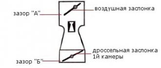
- The starting device is adjusted by changing the position of the cable sheath on the bracket so that the damper is fully open and closed in the extreme positions of the choke button.
- The fuel level in the float chamber is set so that when the top part of the carburetor is inverted and installed horizontally, the gap between the floats and the gasket is approximately 2 mm. After which the level can be checked by attaching the cap, starting the engine, turning off and removing the cap, the distance from the gasoline to the flange should be approximately 24 mm.
More subtle settings are available only to a qualified specialist, since changing some of them leads to disruption of others, so you can quickly bring the device to an inoperative state.
The same can be said about cleaning the carburetor. The use of a rough metal tool will lead to changes in the cross-sections of channels and jets. It is only allowed to wash the parts and channels of the housing with special aerosol carburetor cleaners after complete disassembly.
It should be remembered that in old carburetors the formation of aluminum oxides begins in the channels, which cannot be cleaned, therefore it is recommended to replace the carburetor with a new one every 5-7 years; the fuel savings will justify the costs.
Height adjustment for floats
The caliper will need its depth gauge, which will need to be pulled out to a length of thirty-four millimeters. If you don’t have the necessary tool in the form of a caliper at hand, then a simple and ordinary ruler can help out. You will need to attach it to the cardboard gasket on the carburetor cover and measure the distance from the top of all the floats to the cardboard gasket. The distance should be equal to the same thirty-four millimeters that were measured. If the numbers are not equal to this value, then you will need to bend the levers and tongue until the number reaches thirty-four millimeters.
Selection of jets
Some parameters of serial carburetors are far from the standard ones, since the dimensions of some parts have manufacturing deviations. An interesting and very useful video from which you will learn how to modify the Solex 21083 carburetor.
Thus, the spread in the parameters of some serial carburetor parts can reach up to 5%. Therefore, when adjusting the carburetor, make sure that the jets are in good working order. The selection of jets is carried out taking into account the working volume of the car.
If the engine has a large displacement, then it is necessary to install small jets, since an increase in volume requires more air passing through the diffuser, which affects gasoline consumption. Their adjustment should begin with the fuel jet, and then, if necessary, move on to the air jet.
You need to have several jets available with higher and lower productivity than the installed one.
Our actions:
- Using a wire, secure the throttle valve of the second chamber to eliminate its influence.
- Next, we select the jets, for example, the jet marked “107.5”, which is our basic one, change to “105”, and then “97.5”. We reduce the throughput of the jets until dips appear when the throttle is open or twitching when driving. When these signs appear, you should unscrew this jet and replace it with the previous one, which had a slightly higher performance.
- If dips occur when starting the car, you should enrich the mixture slightly by adjusting the idle system.
If you are trying to increase the efficiency of your car, then it is not recommended to reduce the flow area of the main fuel nozzle of the second chamber, since the acceleration process will be much longer, and all savings will be reduced to zero.
Adjusting the full stroke of the floats
To do this, you need to pick up a measuring tool in the form of a ruler and place it parallel to any float. The ruler must be positioned vertically. After this, the float must be raised, and the lower part will have to rise by fifteen millimeters. This value will be the entire stroke of the float. The same steps will need to be performed for the next float, and if the stroke is not equal to fifteen millimeters, then the rear protrusion will need to be bent.
Idle speed setting
After setting the level in the float chamber, we assemble the carburetor and warm up the car engine to operating temperature. In this video, they will tell you and show you how to set the idle speed in a Solex carburetor, as well as the main reasons for its absence.
Next, we turn it off and carry out the following operations:
- Using a flat-head screwdriver, tighten the mixture quality screw until it stops (position 7).
- We turn it back from this position 4 - 5 turns.
- We start the engine, do not forget to completely remove the choke, and using the mixture quantity screw (position 6) set the minimum engine speed to about 800 per minute so that the engine runs stably.
- We tighten the mixture quality screw until the engine starts to run unstably. Then we turn it back 0.5 - 1 turn, which should bring the engine to a relatively stable position.
- Using the mixture screw, set the engine speed to about 800 - 900 per minute. If the engine starts to stall, unscrew the mixture quality screw a little more.
When setting the idle speed, some problems may arise:
The engine does not slow down when the mixture screw is tightened (a lot of fuel gets into the idle channel and this screw cannot shut it off).
Causes:
- large jets installed;
- the solenoid valve is not tightly screwed in, and fuel is sucked past the nozzle;
- deformation of the nozzle seat or itself.
So, for example, if the engine stalls when removing the wire from the solenoid valve, this means that the jet is installed too large.
Checking the work done
After all the work has been completed, you will need to make sure that it is correct. To do this, you will need to turn the carburetor cap and make sure that the ball on the needle will not be sunk. If the stamping lines on the sides of the floats create parallelism with the cover, this will mean that the work was done correctly and everything is correct. If everything is done correctly, but there is no parallelism, then the problem will be a needle malfunction.
How to check the result of the work?
Without a proper check, if some error suddenly occurs, everything will have to be repeated again - all operations. Therefore, before reassembling, the carburetor cover is placed vertically. The ball should be sunk with a tongue on the float, and the stamping line should be parallel to the cover. If the conditions are not met, you will have to repeat the second stage, since you need to set the fuel level in the Solex carburetor as accurately as possible. And after the check has been completed, you can assemble the assembly as it was, in its original position.
Why is a float chamber needed?
In order for the engine to function properly, it is necessary to maintain the set level of gasoline in the carburetor, which is what the carburetor float chamber does. A stable fuel level is necessary for proper engine operation at various load levels.
If the carburetor did not have a device that regulates the fuel level, it would not be able to work normally. The amount of fuel in the carburetor float chamber is one of the key reasons for its stable operation. The operation of the motor at low speeds and in other transient modes of the primary and secondary chambers depends on it, therefore the functioning of the entire motor depends on the correct functioning of the float chamber.
Setting the idle system affects the operation of the engine in all its modes. The amount of fuel in the float chamber is calculated by the manufacturer so that there is no spontaneous leakage of gasoline into the combustion chamber from the carburetor nozzles. In vehicles with a transverse engine, there is a need to compensate for tidal phenomena. To compensate for this, manufacturers install economizers. More expensive carburetors use paired float chambers, which are located on both sides of the carburetor. These chambers are combined with each other by a transverse channel or a common plane.
Most often, two float valves are used, which are located at the edges of the device. The design of the floats can be hollow from two bronze halves, which are soldered together, or made of porous plastic. To compensate for the effect of engine vibration on the gasoline level, float chamber valve dampers are used. This mechanism is called a damper spring and is equipped with a rod or ball. In some carburetors, the float valve is located at the very bottom of the chamber. With this location, it is possible to check the fuel level by removing the top carburetor cover. Many models of carburetors for this mission are equipped with sight windows, which are located on one of the walls of the float chamber. With such glasses, it is possible to monitor the gasoline level directly while the engine is running.
Basic faults of Solex 21083
There are malfunctions that are most typical for Solex carburetors:
- clogging of the fuel jet of the GDS;
- the entry of debris into the idle system; the XX jet in the solenoid valve is especially often clogged;
- deformation of the lower surface of the main body due to overheating;
- failure of the accelerator pump diaphragm;
- solenoid valve defect;
- loose fit of diffusers in the housing.
If the body is deformed, air is sucked between the carburetor and the intake manifold, and the engine begins to operate intermittently, as the air-fuel mixture becomes leaner. The idle speed is difficult to adjust, and to correct the defect it is necessary to grind the surface on an emery wheel. If the surface warping is significant, grinding will no longer help; the housing must be replaced.
Over time, the accelerator pump diaphragm can crack, lose elasticity, and ruptures appear in it.
Checking the condition of the diaphragm is quite simple; it does not require removing the carburetor. To get to the diaphragm, you need to unscrew the 4 screws of the accelerator pump cover and remove the part. The condition of the diaphragm is checked by external inspection.
There are many different modifications of Solex carburetors, while the 21083 series is the basic version with a minimal diffuser cross-section. This model is usually installed on 1.5-liter engines of VAZ cars. We previously wrote about the “Ozone” setting on models 2106 and 2107.
The enormous popularity of this series is due to the possibility of grooving diffusers. Thus, almost any modification to the carburetor can be made. Experts do not recommend installing Solex on engines with a volume of more than 1.5 liters, as in this case the engine will be “choked” at high speeds. If you intend to configure this carburetor for the UZAM power unit, it is necessary to replace the jets due to the fact that a richer fuel mixture must be provided.
The mechanism of operation of the carburetor float chamber
Gasoline enters the float chamber through a pipe in which the fuel pump creates pressure. A needle-shaped valve and a plastic or brass float control the amount of fuel in the chamber. When the gasoline level decreases, the valve needle, which is in contact with the float, opens the needle valve, after which gasoline enters the float chamber. As the gasoline level increases, the float rises and pushes the rod with its tongue. He, in turn, closes the valve. This cycle is repeated all the time while the motor is running. If there are changes in the fuel level, it will be impossible to achieve stable engine operation.
What troubles can happen with the second camera?
The secondary chamber system cannot be regulated due to the original jets produced at the factory, as well as the econostat located in its planes, since it is this that supplies additional fuel to enrich the mixture when a vacuum forms in the carburetor caused by high speeds.
The acceleration pump nozzle is perhaps the only element that can undergo slight changes in cases where the flow of gasoline does not reach its intended place.
Features of the carburetor float chamber mechanism
The float chamber is located in the front part of the carburetor body. The top is closed with a lid, and gasoline enters the chamber through a fitting. After the fitting there is a filter made in the form of a mesh, the cleanliness of which should be periodically monitored.
The carburetor float most often has a cylindrical shape, made from two brass halves that are soldered together. The float fasteners are made of the same alloy and are secured by soldering. The float is attached to the carburetor cap using a connection.
There are two tongues on the float mount: one is responsible for adjusting the opening of the valve needle, and the second is designed to limit the stroke of the float (so that it does not touch the bottom of the float chamber). The valve is a mini body screwed into the top cap of the carburetor, inside of which there is a needle. A spring damping ball is installed at the end of the needle. This mechanism protects the needle from impacts against the valve body. To prevent the needle from getting stuck in the closed state, a specific bracket is put on it, which is pulled down by the float mounting tab.
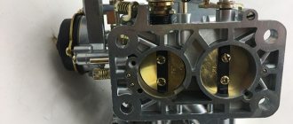
Carburetor calibration data
| Options | 2108-1107010 | 21081-1107010 | 21083-1107010 | |||
| First camera | Second camera | First camera | Second camera | First camera | Second camera | |
| Mixing chamber diameter, mm | 32 | 32 | 32 | 32 | 32 | 32 |
| Diffuser diameter, mm | 21 | 23 | 21 | 23 | 21 | 23 |
| Main dosing system: | ||||||
| fuel jet marking | 97,5 | 97,5 | 95 | 97,5 | 95 | 97,5 |
| air jet marking | 165 | 125 | 165 | 135 | 155 | 125 |
| Emulsion tube type | 23 | ZC | 23 | ZC | 23 | ZC |
| Idle system and transition system | ||||||
| first chamber: fuel jet marking | 42* | — | 40* | — | 40* | — |
| air jet marking | 170 | — | 170 | — | 170 | — |
| Second chamber transition system: | ||||||
| fuel jet marking | — | 50 | — | 50 | — | 50 |
| air jet marking | — | 120 | — | 120 | — | 120 |
| Econostat: | ||||||
| conditional fuel jet flow rate | — | 60 | — | 70 | — | 70 |
| Power mode economizer: | ||||||
| fuel jet marking | 40 | — | 40 | — | 40 | — |
| spring compression force at a length of 9.5 mm, N | 1,5±10 % | — | 1,5±10 % | — | 1,5±10 % | — |
| Accelerator pump: | ||||||
| sprayer marking | 35 | 40 | 35 | 40 | 35 | 40 |
| fuel supply for 10 cycles (total for both chambers), cm3 | 11,5 | 11,5 | 11,5 | |||
| cam marking | 7 | — | 4 | — | 7 | — |
| Starting clearances: | ||||||
| air damper (gap B), mm | 3±0,2 | — | 2,7±0,2 | — | 2,5±0,2 | — |
| throttle valve (gap C), mm | 0,85 | — | 1,0 | — | 1,1 | — |
| Hole diameter for vacuum corrector, mm | 1,2 | — | 1,2 | — | 1,2 | — |
| Needle valve hole diameter, mm | 1,8 | 1,8 | 1,8 | |||
| Diameter of the fuel bypass hole into the tank, mm | 0,70 | 0,70 | 0,70 | |||
| Engine crankcase ventilation hole diameter, mm | 1,5 | — | 1,5 | — | 1,5 | — |
* Selected at the factory when setting up the carburetor.
Adjusting the gasoline level in the carburetor float chamber
An incorrectly set fuel level in the carburetor float chamber may result in the engine not starting. Possible failures in operation when pressing the accelerator, increased fuel consumption, losses in engine power, flooded spark plugs, etc. Adjusting the fuel level in the chamber of a Solex carburetor is not so difficult and does not require special experience or tools.
Adjusting the Solex carburetor
Tools required for work:
In order to adjust the fuel level, there is no need to remove the carburetor from the engine; you only need to unfasten the top carburetor cover.
Work order:
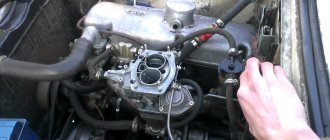
- The air filter housing must be removed. First you need to remove the filter cover by unlatching the four latches and removing the hose from it. Then we take out the filter itself and unscrew the four nuts that secure the filter housing to the carburetor, and remove it;
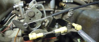
- Next you need to remove the carburetor cover. First of all, remove the fuel supply hoses and disconnect the wiring from the solenoid valve. Then, using a screwdriver, unscrew the screws securing the top cover. Then carefully remove the cover, trying not to touch the carburetor body with the floats;
- The lid must be turned upside down and placed on a flat surface. In this case, the fastening screws will fall out, which it is advisable not to lose;
- We check whether the floats are positioned correctly. The floats should leave a parallel imprint on the cardboard gasket of the top cover. If this is not the case, they need to be bent to the correct position. The floats should not touch the walls of the carburetor float chamber. The tongue that is on the float should be parallel to the needle valve;
- Next, you need to measure the distance between the tongue on the float and the top cover of the carburetor. This is done using a 1 mm thick probe. If the gap does not match, it is necessary to adjust the fuel level.
Adjusting the fuel level
Many car enthusiasts monitor the gasoline level along the lines located on the body of the float chamber, bending the float tongue in one direction or another. In this case, the check is to ensure that when the float is lowered into the chamber, the supply of gasoline stops, and when removed, the level coincides with the marks on the body of the float chamber. This method is quite good, but for better results it is worth making the adjustment recommended by the manufacturer.
- First you need to adjust the height of the floats. Using a caliper, we set the size to 34mm from the carburetor cover gasket to the top of the float in the inverted state of the carburetor top cover. Adjustment is made by bending the float mounting tongue;
- Then adjust the movement of the floats. Using a ruler, measure the distance to the lower corner of the float. Then we raise the float and measure the same distance again. This distance will be the full travel of the float. We measure the work of the second float using the same method. If there is no match, bend the tongue on the floats.
After the adjustment is completed, it is necessary to check its correctness. To do this, place the carburetor cover in a horizontal position and check that the needle is in the open position. We check that the floats are parallel to the plane of the carburetor cover. If they are parallel, it means the setup is done correctly.
Possible problems when setting up XX
When the quantity screw is tightened, the engine does not react at all . This problem can occur when a large amount of fuel enters the idle diffuser. There may be several reasons for this:
- an XX jet of a larger size than necessary is installed;
- the plug or solenoid valve is not tightened properly, so gasoline is sucked in, bypassing the XX jet;
- The jet or its seat is deformed.
To identify the specific cause of the above problem, it is necessary to disconnect the wire from the valve while the engine is running, and the motor should immediately turn off. If this happens, most likely the wrong size XX jet is installed. When the engine does not stall when the power supply to the valve is turned off, it means that fuel is supplied bypassing the exhaust system, including the nozzle itself.
To eliminate the malfunction, first remove the plug or solenoid valve and check the condition of the nozzle and seat for any deformations. If the seat is damaged, you will have to replace the carburetor cover. If no damage or deformation is detected, put the jet on the solenoid valve and lubricate the o-ring with oil. Then we tighten the nozzle with a wrench, holding it with one finger without much effort.
Possible malfunctions in the operation of the float chamber
If the adjustment was carried out correctly, but there is no parallelism, then the needle is not working properly. In such a situation, the valve should be replaced and the adjustment performed again.
If you doubt the serviceability of the needle valve, it should be replaced, since you will not be able to adjust the fuel level (for example, if the fuel level is adjusted correctly, it will overflow).
After completing the work of regulating the fuel level, we assemble the carburetor in the opposite order. If necessary, adjust the idle speed.
Problems in applying the transition regime
Under special conditions, an area of high vacuum forms under the closed carburetor flaps. When they open sharply, the vacuum can instantly decrease, which causes disturbances in the operation of the primary chamber, forming a failure, since at idle speed gasoline was sucked out of the channel through the nozzles.
To eliminate the consequences, the idle jet or pump nozzles are adjusted, changing in order of rotation, in order to eliminate the resulting difficulties with dips and delays when pressing the gas pedal quickly and abruptly.
It is always worth remembering that this kind of manipulation is carried out exclusively with a preheated engine.
Adjusting the accelerator pump
Accelerator pump metering systems
The main task of the accelerator pump is to supply a smooth and powerful stream of gasoline through the open throttle valve of the carburetor (dripping and sluggish streams are not allowed). The stream of gasoline should enter directly into the manifold, without touching the walls of the diffuser and throttle valve.
Flowing of gasoline down the diffuser stack or throttle valve is not allowed, since the car will become very blunt and jerky when you press the gas sharply.
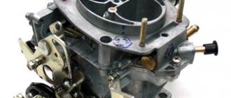
Removing and installing Solex
In order to repair or purge (flush) the carburetor, it must be removed. Removing the unit is quite simple; almost any motorist can do it independently. We remove the device as follows:
- turn off the ignition, first of all we remove the air filter housing;
- remove the return spring from the throttle valve actuator;
- disconnect the throttle cable;
- unscrew the fastenings of the choke cable;
- unscrew the four nuts on which the carburetor body itself is attached;
- dismantle the unit.
Installation is carried out in reverse order.