How to check the phase sensor
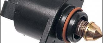
Checking the functionality of the internal combustion engine phase sensor is carried out using a diagnostic tool, as well as using an electronic multimeter capable of operating in DC voltage measurement mode. We will discuss an example of a test for phase sensors of a VAZ-2114 car. On models with a 16-valve engine, a sensor model 21120-3706040 is installed, and on 8-valve engines - 21110-3706040.
First of all, before diagnostics, the sensors must be removed from their mounting location. After this, you need to visually inspect the DF housing, as well as its contacts and terminal block. If there is dirt and/or debris on the contacts, it must be removed with alcohol or gasoline.
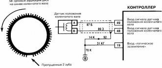
To check the sensor of the 8-valve engine 21110-3706040, it must be connected to a battery and an electronic multimeter according to the diagram shown in the figure.
Next, the verification algorithm will be as follows:
- Set the supply voltage to +13.5±0.5 Volts (you can use a regular car battery for power supply).
- In this case, the voltage between the signal wire and ground must be at least 90% of the supply (that is, 0.9V). If it is lower, and even more so equal or close to zero, then the sensor is faulty.
- Bring a steel plate to the end of the sensor (with which it is directed towards the camshaft reference).
- If the sensor is working properly, then the voltage between the signal wire and ground should be no more than 0.4 Volts. If more, it means the sensor is faulty.
- Remove the steel plate from the end of the sensor, the voltage on the signal wire should again return to the original 90% of the supply voltage.
To check the phase sensor of a 16-valve engine 21120-3706040, it must be connected to a power supply and a multimeter according to the diagram shown in the second figure.
To test the corresponding phase sensor, you will need a metal piece with a width of at least 20 mm, a length of at least 80 mm and a thickness of 0.5 mm. The verification algorithm will be similar, however, with other voltage values:
- Set the supply voltage on the sensor to +13.5±0.5 Volts.
- In this case, if the sensor is working properly, then the voltage between the signal wire and ground should not exceed 0.4 Volts.
- Place a pre-prepared steel piece into the sensor slot where the camshaft reference is placed.
- If the sensor is working properly, then the voltage on the signal wire should be at least 90% of the supply voltage.
- Remove the plate from the sensor, and the voltage should again drop to a value of no more than 0.4 Volts.
In principle, such checks can be performed without removing the sensor from its mounting location. However, to inspect it, it is better to remove it. Often, when checking a sensor, it makes sense to check the integrity of the wires, as well as the quality of the contacts. For example, there are cases when the chip does not hold the contact tightly, which is why the sensor does not receive a signal to the electronic control unit. Also, if possible, it is advisable to “ring” the wires going from the sensor to the ECU and to the relay (power wire).
In addition to checking with a multimeter, you need to check for relevant sensor errors using a diagnostic tool. If such errors are detected for the first time, you can try to reset them using software, or simply by disconnecting the negative terminal of the battery for a few seconds. If the error appears again, additional diagnostics are needed using the above algorithms.
Typical phase sensor errors:
- P0340 - no camshaft position sensor signal;
- P0341 - valve timing does not coincide with the compression/intake strokes of the cylinder-piston group;
- P0342 - the signal level in the electrical circuit of the DPRV is too low (detected when there is a short to ground);
- P0343 - the signal level from the meter exceeds the norm (usually occurs when the wiring is broken);
- P0339 - an intermittent signal is received from the sensor.
Thus, if these errors are detected, it is advisable to perform additional diagnostics as quickly as possible so that the engine operates in optimal operating mode.
Source
We check the mass air flow sensor on a VAZ-2110 with a multimeter
The sensor block, the first wire may not be there - this is normal.
To do this, we need to understand the pinout and the sensor connection diagram. As you can see, the block has only five wires:
- + 12 Volt.
- + 5 Volts.
- Total ground (green wire).
- Air temperature output signal.
- Air flow signal output (yellow wire).
Electrical diagram for connecting the mass air flow sensor.
The pinout may differ in different firmware versions and on different sensors. Everything is clear with the first two contacts - take a multimeter and check the presence of voltage when the ignition is on. If there is no signal, we look for the cause either in broken wires or in poor contact. Now we check the main indicator - the accuracy and magnitude of the air flow signal. By the way, this can be checked without a multimeter, using the on-board computer, if one is installed:
- We go to the menu, look for sensor parameters.
- Find the voltage Udmrv.
- The rating for all of the above modifications is from 0.996 to 1.01 V.
The platinum thread gets tired over time and distorts the impulse upward. A change of even one hundredth of a Volt is unacceptable. If the computer is not installed, we use a multimeter. We check the voltage between 3 and 5 (minus) contacts, setting the measurement limits on the multimeter to 2 V. Turn on the ignition, but do not start the engine.
The scale shows 1.00 - the sensor is in excellent condition.
On a scale of 1.26 – the sensor is “dead”.
Check table
We evaluate the result using this table:
| 0.99-1.02 V | The condition of the air flow sensor is excellent, close to new |
| 1.02-1.03 V | Sensor in good condition |
| 1.04-1.05 V | The platinum thread is worn out, you need to think about replacing the sensor |
| More than 1.05 V | The sensor does not work, urgent replacement is necessary |
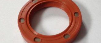
Replacing DPKV VAZ 2112 with your own hands
Having accurately determined the breakdown of this part, you can begin to replace the sensor yourself. To perform this operation you will need the following tools and materials:
- Set of wrenches and socket heads.
- New DPKV.
- Slotted screwdriver.
- Rags.
It is recommended to carry out work on replacing the DPKV in the following sequence:
- Place the car on a flat surface.
- Secure the machine with wheel chocks and apply the parking brake.
- Disconnect the negative terminal of the battery.
- Using a screwdriver, pry up the block with wires and disconnect it from the DPKV.
- Using a 10mm socket wrench, unscrew the bolt holding the sensor.
- Remove the DPKV.
After troubleshooting the seat, a new part is installed in the reverse order of removal. After completion of installation work, the functionality of the DPKV should be checked.
For this purpose, you need to start the engine, warm it up and drive the car for several kilometers under different loads on the internal combustion engine. If no abnormalities are found, then replacing the crankshaft sensor can be considered successful.
Crankshaft sensor: why does it break and how to replace it?
December 10, 2013
Probably every car enthusiast has found himself in a situation where one fine day, after turning the ignition key, his “iron friend” completely refuses to start. Oddly enough, the reason for this may be not only a dead battery or a burnt-out starter, but also a crankshaft sensor. If its body has been deformed or the entire structure has moved a couple of millimeters to the side, this part needs to be replaced. And when your garage neighbors tell you that replacing this element is a rather complicated operation that requires special, expensive tools, do not believe these words. You can change the crankshaft sensor yourself. Moreover, by doing this kind of work, you save a lot of money on service station services and at the same time gain experience in this area. Therefore, today’s article will be important for all motorists.
Why does the crankshaft sensor fail?
Based on the readings of this part, the injection system synchronizes the operation of the injectors and ignition. Therefore, injection is not possible without this part. And when the crankshaft sensor stops working, interruptions begin in the engine. Therefore, not a single modern car can do without this small spare part. And in order to prevent this malfunction, you need to regularly check the condition of the sensor. But when the symptoms began to become reality, the driver had no choice but to urgently replace it.
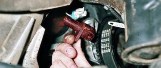
How to remove the crankshaft sensor?
Let us immediately note that this procedure can be performed without a special lift. So, let's get to work. First, unscrew the sensor mounting bolts that connect it to the gearbox. In fact, to remove the necessary spare part, we only need this stage. But since this part is located in a very hard-to-reach place (almost on the bottom), we will have to work hard. To work we need an extension cord, an 11 mm wrench and, of course, good lighting
It is important that the length of the first part is about 80-90 centimeters. If you have these tools, unscrew the bolts
But before you remove the crankshaft sensor, pay special attention to the rubber pad. If in the future it is poorly installed or its gap is equal to at least 1 millimeter, all readings of the measuring device will be inaccurate, and, accordingly, the engine will operate intermittently
It is best to mark this part and put it in a separate place.
The entire process of removing the spare part, bolts and lining must be carried out with great care. This part doesn't like rough handling.
Next, take a new crankshaft sensor and mount it in place of the old one. During installation, this element should be lowered through the entire engine compartment so as not to catch the connector from the installed element on top. Then don't forget about the gasket. We mount it carefully and check the integrity of the structure
It is important that the gap between it and the sensor is minimal or completely absent. After this, we attach the wires to the part, connect all the connectors and start the ignition
If you did everything correctly, rest assured that the engine will start with half a turn.
Unforgivable Movie Mistakes You Probably Never Noticed There are probably very few people who don't enjoy watching movies. However, even in the best cinema there are mistakes that the viewer can notice.
13 signs that you have the best husband Husbands are truly great people. What a pity that good spouses don't grow on trees. If your significant other does these 13 things, then you can s.
7 Body Parts You Shouldn't Touch with Your Hands Think of your body as a temple: you can use it, but there are some sacred places that you shouldn't touch with your hands. Research showing.
Contrary to all stereotypes: a girl with a rare genetic disorder conquers the fashion world. This girl's name is Melanie Gaydos, and she burst into the fashion world quickly, shocking, inspiring and destroying stupid stereotypes.
Never do this in church! If you are not sure whether you are behaving correctly in church or not, then you are probably not acting as you should. Here's a list of terrible ones.
Why do you need a tiny pocket on jeans? Everyone knows that there is a tiny pocket on jeans, but few have thought about why it might be needed. Interestingly, it was originally a place for storage.
Dismantling and installation
Thus, it was determined that DPCV had failed. Therefore, there is nothing else left to do but replace it. To do this you will have to disassemble the old device.
- Turn off the ignition and open the engine hood. Attach it securely to avoid unpleasant blows to your back or head.
- Remove debris from around the sensor so it can be removed and inspected.
- Disconnect the wiring harness from the appropriate connector.
- With a 10mm wrench you can remove the crankshaft sensor mount quite easily.
- Remove the damaged device.
- At the same time, it is necessary to check the generator drive gear. It often fails, causing the device to not work properly. Due to these modes, error codes appear in the on-board computer.
- If there are no malfunctions and nothing prevents you from installing a new device, proceed with the installation.
- If necessary, remove burrs from the DPKV installation site.
- Insert the new meter into the socket and tighten the clamp screw. Do not exceed a tightening torque of 12 Nm.
- Be sure to use the gasket already provided by the responsible sensor manufacturer.
- Use a feeler gauge to check if there is 1mm clearance between the pulley and the VPCV core.
- The backlash error should not exceed 0.41 millimeters upward. Never allow less than 1 mm of play.
Maintaining ground clearance
All about the crankshaft position sensor
As mentioned above, replacing the crankshaft sensor on a VAZ 2110 is not done just like that. If this small and seemingly inconspicuous-looking device is not the main part or assembly of the car, its malfunction leads to several problems. Let's look at them.
Let's get started:
The first case implies this option when dirt from or oil from under the engine cover gets on the sensor. In this case, the sensor fails, and the car starts poorly, accelerates very sluggishly and the engine speed barely reaches 3000. The car system announced this by completely turning off the emergency lights, and the BC not immediately, but after a certain time, gave a signal that an urgent replacement of the crankshaft position sensor of the VAZ 2110 is required;
- The car drives normally, but the on-board computer constantly sends signals that there is a problem with the sensor. What to do in this case? You can try moving the wires, as the cause may be hidden in bad contacts. The car constantly shakes while driving, and the contacts can oxidize over time. In addition, all wiring may be damaged.
- The car started normally, but then it stalled, and I couldn’t start it again. After a certain time, the engine starts again normally, but stalls again. And in this case, the reason may lie in the wiring. In many cases, the wire going to the sensor burns out because it comes into contact with the hot exhaust manifold.
This video will help you replace the sensor yourself correctly. In addition, it is recommended to use photo instructions and other information media during the replacement process. As it becomes clear from this article, you can do a lot of things on your car with your own hands. The main thing is the instructions that you need to follow, and the rest will follow. All that remains is to do the following if problems are discovered: buy a new sensor, the price of which is not too high, and proceed with replacement.
The crankshaft position sensor (CPS) is also called a synchronization sensor, since it synchronizes its operation with the operation of the engine.
Symptoms of a problem
Your car may indicate in different ways that there is a problem with the DPKV or just the DC. Let's name the main ones.
- It is not uncommon for dirt to form on the end of the sensor, causing the device to transmit information incorrectly.
- At idle, the engine behaves unstable.
- The power level of the power unit drops noticeably.
- The revolutions can spontaneously increase or, conversely, fall.
- During acceleration, dips are noticeable.
- When you turn on the ignition, problems are felt and it can be difficult to start the car.
If you discover such problems, most likely you will have to replace the DPKV. In addition, we are talking about a consumable that will not cost you a fabulous amount of money.
This crankshaft position meter cannot be repaired.
Additionally, we advise you to pay attention to the error codes that appear. Codes with designations 0336 and 0335 indicate that a wire break may have occurred near the connector. This problem can be easily determined by visual inspection.
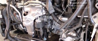
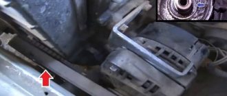
Location
Many VAZ 2114 owners prefer to carry out repairs with their own hands. This allows you to save significantly.
But in order to replace the DPKV, you need to find out exactly where it is located.
The desired object is located on the engine. To be more precise, on the oil pump in the immediate vicinity of the generator drive pulley. Look for the sensor on the pump cover. Fastening is carried out with one bolt.
Reasons for failure
There are several main reasons why the DPKV may eventually fail and lose its functionality.
- Physical deformation of the body has occurred. It is made of plastic, so such breakdowns are not uncommon.
- A short circuit may occur between the turns of the winding, which changes the generation frequency, which is transmitted to the electronic control unit. Such a breakdown is typical if a frequency-type DC is used.
- Simple wear or breakage of pulley teeth is another common reason why the crankshaft sensor needs to be replaced.
How to remove and replace the crankshaft position sensor on a Chevrolet Niva
To synchronize the position of the shaft with the electronic unit, the design of the Niva Chevrolet car is equipped with a crankshaft position sensor.
This device is located not far from the drive disk, and is located on the timing cover of the mechanism drive itself.
This disc is a wheel with fifty-eight teeth, and to create a certain impulse between the TDC (top dead center) and the ECU, a couple of teeth are specially removed.
Due to the fact that the crankshaft rotates, the drive disk rotates. The position of the ECU shaft is determined due to the fact that during the rotation of the disk at the sensor, magnetic fields change, thereby forming an alternating current pulse.
Sensor device
The structure of this element is the simplest, it consists of:
- Nylon frame
- This frame is wrapped in copper wires
- Has a steel core
- Insulation is provided by enamel, the base of the sealant is a compound resin
They come in different types, namely:
- The stroke sensor also distributes the ignition.
- Magnetic
- Optic
Symptoms of a problem
Sooner or later, the sensor becomes unusable, this leads to problems starting the Chevrolet Niva car, and sometimes even to the inability to stop the car while moving. The fuel supply and ignition timing depend on the position of the sensor.
- If while driving you notice a decrease in the dynamics of the car, this will indicate that this element is not corrected,
- This malfunction can also be indicated if the Check light comes on.
- In addition, a faulty sensor can be determined by the generator and timing drive.
- The revolutions go up and down and it all happens without your participation.
First of all, the position of the sensor is checked; the reason for checking may be the slightest resource cost. Also, using diagnostics, you can simply determine whether the device is fixed or not. Diagnostics means removing the product and reinstalling it; it will be in good working order if its values are approximately from 550 to 750 Ohms.
Removal, installation and inspection
Also, the first sign that it has failed is the occurrence of detonation under heavy loads on the engine itself, instability of idle speed, and a decrease in engine power. The state of the node can be understood in several ways. You just need to have the necessary equipment. If the necessary devices are available, we proceed to removing the element.
To remove it and check it, you need to do the following procedure:
- We remove the block with all the wires from it
- Unscrew the screw that secures the crankshaft sensor itself and remove it
- We check with a tester whether it is working or not
- We install the new element in place in the reverse order of removal.
By external signs you can determine the condition of the pads, the DPKV housing and whether the contacts are damaged. If no visual defects are detected, then we proceed to the inspection itself. It is carried out by means of ringing, and as mentioned above, the winding resistance should not exceed 759 Ohms, and not less than 550.
To summarize, we can conclude that this unit is the main one in the electronics, which is responsible for controlling the engine, since if it fails, then starting the engine will be impossible, so it is best to always carry it with you to insure yourself against such unpleasant consequences spare part.
If you do diagnostics and subsequent replacement, it will not take you much time and effort. The main thing is to adhere to clear rules for installation and dismantling. To extend the service life of all important elements of the Chevrolet Niva engine, timely and proper care should be carried out, not only for this device, but also for other parts.
Functionality check
If you decide to check the serviceability of the sensor yourself, treat this procedure responsibly and carry it out correctly. On a VAZ 2114 car, the crankshaft sensor is checked in several ways.
- Using a multimeter. The serviceability of the induction sensor can be assessed by the resistance of its coil. In a working product it is 500-700 Ohms.
- On the multimeter, set the measurement limit to 200 millivolts, connect the probes to the terminals (where the standard wires are connected). Pass a steel object several times in front of the core. The working sensor will “see” the metal and there will be voltage spikes on the multimeter display. If there are none, replace the part.
- But the most accurate results when checking are provided by an oscilloscope. When using this device, one hundred percent results can be guaranteed; it reads all the information from the sensor while the engine is running. It can be observed on the device screen. The engine, during tests, should operate at different speeds. They start with eight hundred revolutions, then two thousand, and raise it to six thousand. If the lines (on the device screen) are of different lengths, you need to look for the cause of the malfunction. Remove dirt, check the pulley for defects, and so on.
Oscillogram of a working sensor
Oscillogram of a working VAZ 2114 crankshaft sensor
It should be noted that these verification methods work on all VAZ models with DPKV. If you have any doubts about your own abilities, then contact the service. Thanks to specialized equipment, the result will be more accurate, and the check will not take much time.
Remove from the engine
The malfunction has been identified. Let's start eliminating it. Let's look at this operation using the VAZ 2114 as an example.
Turn off the car ignition. We open the hood, fix it firmly, and visually determine where the VAZ 2114 crankshaft sensor is located. Before removal, it is advisable to remove all contaminants in the area where it is located. Next, carefully remove the block with wires from the connector.
Using a “10” wrench, unscrew the fastening bolt.
Removing the crankshaft sensor on a VAZ 2114
After dismantling the sensor, it is advisable to check the generator drive toothed pulley for defects. Since its damage can introduce errors into the operation of the entire system.
After we are convinced that there are no defects of any kind, we proceed to assembly. The seat must be clean. We install the new part in place and fasten it with a bolt (the tightening torque should not exceed 8-12 Newton meters). In this case we use adjusting washers. They are sold complete with a new sensor. Thus, using a special probe, we ensure that the gap between the pulley and the sensor core is one millimeter. The permissible error is 0.41 millimeters in the larger direction.
The gap between the pulley and the crankshaft sensor core on a VAZ 2114
We connect the block with wires into place.
After installation and checking the gap, we try to start the engine. With a confident start and stable operation of the engine, we can say that the repair was carried out successfully.
Despite the fact that the breakdown of the synchronizing sensor is not frequent, knowledge of its symptoms and consequences, as well as methods of elimination, will be useful to the car enthusiast.
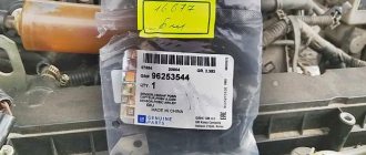
New sensors are available in almost any auto parts store. The price of DPKV can vary between 200-400 rubles. How much a VAZ 2114 crankshaft sensor costs depends on your region, the location of large spare parts stores nearby (usually cheaper there) and the greed of the seller. Can be ordered in the online store. When purchasing, take the old one with you so as not to make a mistake in choosing a model. To avoid defects and repeated purchases, it is advisable to purchase from well-established sellers.
The crankshaft or crankshaft position sensor is an electromagnetic device that transmits data about the current position of the crankshaft to the electronic engine control unit. It is difficult to overestimate the importance of this device, since the correct operation of the injectors responsible for supplying fuel, as well as the entire ignition system as a whole, depends on its performance.
AC voltage measurement
Checking the VAZ 2114 dpkv by measuring the variable component of the output signal is as follows. In order to measure the alternating component of voltage, it is necessary to ensure the appearance and absence of metal at its sensitive surface with a frequency of at least 200 Hz. To do this, you can use an auxiliary motor with a disk and a slot or protrusion, depending on the type of sensor. And power the sensor winding with a constant voltage of 1 or 2 V. Then switch the multimeter to the voltage measurement mode with a limit of up to 2 V of the alternating type. Next, you need to take a capacitor with a capacity of at least 1 μF and connect it to one of the terminals of the crankshaft position sensor, and the other end to one probe. Place the second probe on the second contact of the coil and turn on our resulting stand. Voltage should appear on the device readings when the disk rotates, this indicates that it is working properly. But, unfortunately, you will not see this voltage rating in the passport data. Because it depends on the selected capacitance, the more you increase it, the closer the readings will be to the supply voltage.
Functionality check
Don't rush to conclusions. You shouldn’t blame DPKV for all the troubles. Sometimes it turns out that the cause of the problem is completely different. Therefore, first you should check whether your DC is working or not.
There are several ways to check.
- Multimeter. Your task is to measure the coil resistance on the induction sensor. If it is working properly, then the indicator will be from 500 to 700 Ohms.
Multifunctional multimeter
- Set the measurement limit on the multimeter to 200 millivolts, connect the probes to the output and pass a metal object around the core several times. If the sensor is working, it will be able to detect this metal and a voltage spike will appear on the display. If there are no surges, the DC must be replaced.
- An oscilloscope. This verification method gives the most objective and accurate result, equal to almost 100%. Connect the device to the engine and read data in different modes. The engine will need to be started at different speeds - from 800 and above, up to 6 thousand. Look at the lines appearing on the screen. If they are of different lengths, you should look for the reason for the malfunction. Sometimes simple cleaning of dirt, checking the pulley for damage and other measures helps.
Features of injection systems
The injection system operates thanks to a sensor system and a control unit. All signals are input to the microprocessor unit, which regulates the operation of the actuators. The following sensors are responsible for the correct operation of the engine:
- Crankshaft positions.
- Camshaft positions (not on all versions).
- Intake manifold pressure.
- Lambda probe.
- Speed.
- Mass air flow.
- Throttle position.
And the main role is played by the VAZ-2110 crankshaft sensor (8 valves or 16), since the moment of injection and supply of high voltage to the spark plug electrodes depends on it. The design has a temperature sensor, but it has virtually no effect on operation. It is necessary to control the engine temperature and send a signal to the dial indicator (or to the on-board computer). But it will be indispensable if it is necessary to implement automatic switching of fuel types (from gasoline to gas and back).
Types of sensors
There are three types of DPKV, which differ in their principle of action.
- Inductive (magnetic). We have already discussed its principle of operation above. It is based on electromagnetic induction. This type of sensor is most widely used due to its efficiency and reliability. It is worth noting that for its operation and the formation of a stable signal, high speeds of the master disk and the absence of obstacles between it and the sensor (contaminants) are required.
- Hall Sensor. This type of DPKV works based on the Hall effect. When the disc teeth pass through the sensor, it produces a small signal voltage. The data is recorded and transmitted to the control unit in the form of a discrete signal. Such sensors use a reference voltage and are highly accurate, but are rarely used as DPKV.
- Optical. The operation is based on a light source and receiver (LED and photodiode). The teeth of the disk pass between them in the gap. At different rotation speeds, the teeth of the disk obscure the LED, as a result, pulse signals are formed on the photodiode, which are fed to the control unit. Due to their impracticality, such sensors are now almost never found in cars.
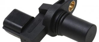
The device and where the crankshaft position sensor is located
The sensor has a simple design. Inside there is a magnetized steel rod with a copper wire winding. The rod and winding are placed in a plastic case and filled with compound resin to insulate the wires. From it comes a standard electrical connector that connects to the car's electrical system. The DPKV is fixed on the cylinder block or gearbox housing. It can also be mounted on a bracket near the drive pulley.
Inductive sensor device
The sensor is located opposite the teeth of the drive disk. Sometimes it can be called synchronizing or reference. It is a disk with teeth along the outer circle. Can be mounted on a crankshaft pulley or flywheel and rotate with it at the same frequency.
Symptoms of a problem
Signs of a malfunction of the DPKV can be different. Often, dirt adheres to the end of the sensor itself, which can interfere with reading. Also, symptoms of a faulty crankshaft sensor may be as follows:
- The idle mode is unstable;
- Engine speed rises or falls spontaneously;
- Power drops;
- During acceleration, a “failure” is felt;
- The car doesn't start well.
In these cases, for the most part, the VAZ 2114 crankshaft position sensor is replaced.
In addition, the VAZ 2114 crankshaft sensor may well be in good working order. And on the “tidy” the DPKV error will appear (0335 or 0336). The reason for this may be a broken wire near the connector. This is easily determined visually; then it is enough to replace the connector without replacing the sensor itself.
If the owner notices signs of a malfunction of the crankshaft sensor on his car, then this is a “signal” about the need for diagnostics.
It’s not difficult to guess where the crankshaft sensor is located on a VAZ 2114 . Like many other VAZ models, it is attached to the engine, and more specifically to the oil pump, near the generator drive pulley, on its cover. The sensor is attached with one bolt, which is typical for many models of this family.
Here is the crankshaft sensor on the VAZ 2114
Typical causes of failure:
- Physical damage to the case;
- The interturn closure of the winding turns entails a change in the generation frequency transmitted to the control unit (frequency type sensors);
- Emergency wear or loss of pulley teeth.
Construction types
The VAZ 2115 is equipped with two types of crankshaft sensors, which differ in design, but have the same principle of transmitting the read signal. The operation of any controller is based on two components:
- sensing element;
- toothed disc (synchro disc).
The master or synchro disk is installed on the crankshaft and has the same rotation speed with it. The disc rim is divided by 58 teeth, the empty space of two teeth is occupied by the synchronization point. The tracking element is located at a certain distance from the transverse axis of the disk, captures the moment of tooth transition and transmits the number of crankshaft revolutions to the computer.
According to the type of design, the sensors on the VAZ 2115 can be of the inductive type and based on the Hall effect. Optical sensors that use a light beam are rarely installed on cars, since the engine compartment is often highly dusty. There is a danger that the sensitive element of the light catcher will be clogged with grease, oil, etc.
The magnetic controller for VAZ is based on a core with a winding installed in a plastic case. The principle of signal transmission is based on the law of electromagnetic induction. On the winding of the core, when a part of the disk without a tooth passes next to it, there is no current; when a part of the disk with a tooth approaches, a magnetic field arises, the winding is excited, current induction appears, and a stable electrical signal is formed, which is transmitted to the ECU.
The advantages of the magnetic sensor are obvious: its operation does not require power from the on-board network. Accordingly, the risk of breakdowns is reduced; during diagnostics, only the condition of the winding, core and signal quality to the ECU are checked.
DPKV, the operating principle of which is based on the Hall effect, requires connection to the on-board network. The operation is based on the occurrence of voltage on two plates through which current passes.
The cost of controllers for the entire VAZ line starts from 200 rubles, so parts are not repaired, only replaced.
How can I check the serviceability of the DPKV?
Nowadays, the most popular are 3 methods, which are carried out quickly and provide information about the performance of the sensor with high accuracy.
When measuring the resistance of a winding set on a sensor, you can use a special device - an ohmmeter (or in other words, a multimeter). When checking, the device should show a value in the range of 550-750 Ohms.
Testing process - the resistance of the coil in the inductive sensor is measured. If the coil on the sensor is damaged, then first of all the damage will be reflected in the resistance value. That is why, at the beginning of the diagnosis, the required range is set and the correct operation of the element is checked using probes.
This type of check is basic and most elementary, but it cannot give 100% confidence in the serviceability of the spare part.
Comprehensive diagnostics of the crankshaft position sensor
The second method of checking the sensor for functionality is considered more labor-intensive and requires a whole range of instruments that are only available in car repair shops. To carry out the work you will need:
- Megaohmmeter model;
- Special network transformer for data decryption;
- Standard sample of inductance meter;
- A regular digital voltmeter.
Using an ohmmeter, as before, we measure the resistance. Using an inductance meter, we measure the induction value on the winding. In good condition, the sensor gives a value of 250-400 mH. After this, we measure the insulation resistance value, which at a voltage of 500 V should be 20 MOhm. In this method, a network transformer is needed when periodic magnetization of the sensor occurs. If the sensor is in good condition, all received data should be within the established limits.
Diagnostics of the crankshaft position sensor signal using an oscilloscope
This method of diagnosing the crankshaft can be considered the most accurate, since not only the crankshaft component is checked, but also its design itself during operation of the machine. The point of the procedure is to connect an oscilloscope to the crankshaft position sensor and monitor the values emanating from it using a program. With this method, there is no need to remove the device from the engine - all work is carried out with the car running.
Functional testing steps:
- A black clamp, called a “crocodile” among experts, is connected to the engine ground of the vehicle being tested;
- Next, the probe probe is installed parallel to the signal terminals of the sensor itself (a characteristic connector with the terminal designated by the letter A);
- Then the second connector of the oscilloscope probe needs to be connected to the corresponding analog input of the computer where the program is installed;
- If all the component wires are correctly connected, you will see on the monitor screen the signal from the oscilloscope in the form of a graph with the signal voltage directly at the DCPV input;
- For analysis, you need to select a special mode for displaying the constructed oscillogram - it calls it “Inductive_Crankshaft”. After this, all that remains is to start the car engine and monitor the values received from the sensor.
If you receive a signal from a sensor whose output parameters do not correspond to normal values, you will be able to observe a sharp twitching of the machine’s motor, as well as difficulties when starting it. The presence of these violations when analyzing the output signal of the DCPV will indicate the occurrence of malfunctions:
- In the design of the sensor itself;
- In the element defining the synchronization disk;
- In the teeth.
Which part of the device ultimately became unusable can be understood only after analyzing the nature of the change in the waves of the device on the oscillogram. As a rule, it is not the sensor itself that needs to be replaced, but the gear wheel, which has become unusable during operation.