Dimensions of standard wheels
A peculiarity of domestic car models, including the Chevrolet Niva, is the lack of individual wheels for a specific year of manufacture of the car.
Common wheel sizes for Niva Chevrolet:
- rim width 8 inches;
- rim diameter 15 inches;
- offset ET40 – distance between the plane of fastening and symmetry.
Failure to comply with these parameters may result in:
- rapid wear of mechanical parts and components of the vehicle chassis;
- Excessive load on the wheel arches of a car and their breakdown, for example, the use of wheels with a dimension greater than R16 and a high rubber profile, will negatively affect the condition of the fender liner. Its surface will be erased. On the Internet you can see a large number of photos devoted to this topic.
Another important parameter is the bolt pattern or drilling of the disk. It is designated by the Latin letters PCD. For Niva Chevrolet it is installed by the manufacturer with dimensions 5x139.7. The number 5 means that the disk is fixed to the hub with five bolts, which are located on a circle, and the distance between adjacent fastening bolts corresponds to 139.7 mm.
The center hole (DIA) of the rim is 98.5mm
Therefore, when choosing a wheel, you need to pay special attention to this parameter, since a discrepancy from the standard even by 1 mm will certainly affect the quality of the disk fastening to the hub. After some time, due to a loose fit, the hub will simply wear off
And the last no less important parameter is the ET offset, which should not exceed a value of 40. Otherwise, this will lead to failure of the internal bearing. The most acceptable offset for the Niva Chevrolet is ET35.
Cylinder head assembly and installation on a Chevrolet Niva engine
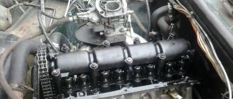
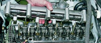
The Chevrolet Niva engine head is not particularly different from other VAZ heads. On VAZ 21213 engines, hydraulic compensators were installed from the factory to avoid problems with valve adjustment. But on our engine head, someone has already replaced the hydraulic compensators with ordinary toy soldiers with manual adjustment of valve clearances.
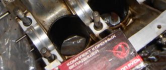
The engine was disassembled due to the formation of an emulsion in the lubrication system. The cylinder head was being crimped and a rotten cooling system plug was discovered. The formation of holes in the cylinder head plugs is a very common problem in VAZ engines. This happens mainly due to poor quality coolant. Car enthusiasts save their money and purchase low-quality antifreeze, and then wonder why their power unit failed so quickly... After the above manipulations, the engine was reassembled and continued normal operation
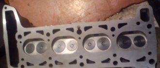
This photo report will show step by step the process of assembling the Chevrolet Niva cylinder head and its installation on the engine block. The engine head plugs were welded, the head was planned, and the valves were ground in.
Maximum and minimum possible parameters of non-standard disks
Some car owners strive to install beautiful wheels of a larger size on their car than those supplied by the manufacturer. The Nyva Chevrolet body allows this to be done thanks to the design of the car's wheel arches. Wheel sizes that do not require modifications to the body are considered 215/75 with a minimum offset of 35.
If the driver has installed a tire with a profile over 215mm, then the arches will have to be trimmed a little, and the ET offset should exceed 58mm. The most optimal reach size is 40-45. Therefore, when planning the installation of new wheels and tires, you need to carefully study this issue. To do this, special websites are offered to help the car enthusiast, where on videos and photos you can see in detail the entire procedure from choosing a wheel to replacing it.
Properly selected wheels and tires are the key to stable vehicle performance on the road.
Removing the cylinder head cover
Tightening torques for the main threaded connections of lawn next since 2014
Place the machine on a pit or ramp.
First, the holders of the brake booster pipe and the throttle valve drive cable should be disconnected from the cylinder head cover. They are mounted on special brackets on the left and right sides of the block.
Next, use a 10mm wrench to unscrew the bolt securing the air duct couplings. Move it aside. Next, using a screwdriver, slightly loosen the clamp of the crankcase ventilation pipe, which connects it to the air duct. Now use a 10mm socket to unscrew the bolts holding the cylinder head cover. The order is not important here.
OLYMPUS DIGITAL CAMERA
After that remove:
- brackets for the throttle cable and motor screen;
- lid pressure washers;
- ventilation and air hoses.
Next, all that remains is to remove the cylinder head cover.
Pros and cons of secret fasteners
To prevent your Chevrolet Niva from being “taken off” the next night after installing new tires, it is recommended to install 1 secret nut on each wheel. No matter how new technologies develop, more reliable means of stingray theft have not yet been invented. Hence the first and main advantage of the secret: such fasteners will help protect much more expensive property from thieves than it is worth.
Modern secrets are no match for the first ones that appeared in distant Soviet times
They are structurally more perfect and differ in aesthetics, which is important. The part is an extended nut with an adapter for an individual key
If you choose closed-type decorative fasteners of the same length for it, then the wheel as a whole will look quite aesthetically pleasing.
The secret mount is very useful for the spare wheel of the Chevrolet Niva, which is screwed to the bracket on the rear door with ordinary nuts, and therefore most vulnerable to thieves. To unscrew secrets, the following types of keys are made:
To prevent the nut from being grabbed by a gas wrench or other similar tools, the lock on top is equipped with a rotating bushing (shell), and the place for the wrench is located in a recess. Cheap products and fakes may not have a shell, so you cannot buy such nuts. The disadvantages of secrets are:
- The tightening torque is weak, so the remaining nuts must be held securely;
- any tricky fastener can be unscrewed if the thief has the time and opportunity to do so;
- the need to always have the key with you and not forget it under any circumstances.
The last drawback is a real scourge of forgetful drivers. If the ramp of exits 2 is punctured: go get the key or call a tow truck, otherwise the wheel cannot be removed.
Friends, hello everyone! I have a question about wheel nuts. There are alloy wheels, regular nuts are screwed on. Does it make sense to buy special nuts for discs or not? Does this somehow affect the vibration, beating of the steering wheel at a speed of 100-110 km/h?
Read more: Total 8900 10w 40
Why change the mount?
There are several reasons why Niva car owners change their wheel nuts to new ones:
Old nuts that are worn or mechanically damaged do need to be replaced, especially when they have poor threads or missing edges. It is difficult to tighten such a part with a torque of 10-11 kgf/m to securely fasten the wheel. It’s better to install a new set; it’s pointless to change 1-2 fasteners. The main thing is that the threaded part of the stud remains normal.
Alloy wheels, although thicker than stamped steel ones, can theoretically be fastened with factory nuts. Another thing is that such details will ruin the entire appearance of the new wheels, so in such a situation it is better to install elements that are in harmony with the wheel. There is another point: in some models of alloy wheels, samples are made in the form of a hemisphere, rather than a cone. Then the standard fasteners will definitely not fit; you need to purchase nuts with a spherical end that fit into the mating part of the rim.
In addition to improving the appearance of the car, there is another reason that forces you to change 1 out of 5 nuts to a special one that can only be turned with an exclusive key. The reason lies in the high cost of car tires and storing the car itself in the open air in the yard, as often happens in cities. To prevent tires from being stolen at night, one clever security nut is installed on the car.
Adjusting the wheel bearing
To work, you will need an indicator and a torque wrench.
To prepare for adjusting the wheel bearing, you must perform the following operations:
- Secure the indicator by resting its leg on the hub near the adjusting nut.
- Place spanners on the studs and secure them with nuts.
- Rotate the hub and move it axially. (Screwed spanners are used as handles).
- Measure the amount of axial movement (clearance) of the hub, guided by the indicator readings.
- If the stroke exceeds 0.15 mm, adjust the play.
The adjustment is carried out as follows:
- Straighten the collar of the nut.
- Unscrew it with a spanner.
- Install a new nut and tighten with a force of 2 kgf*m.
- Loosen the nut and tighten again with a torque of 0.7 kgf*m.
- Loosen the tension by turning the key 20-25 degrees counterclockwise.
- Check hub play.
- Make sure that the indicator readings correspond to the norm (0.02-0.08 mm).
- Lock the nut by pressing its edge into the groove of the outer CV joint.
You can adjust the hub play without using a torque wrench. To do this you need:
- Tighten the nut tightly.
- Rotate the wheel a few turns.
- Check the play.
- If necessary, loosen or tighten the nut slightly.
- Continue until the free play of the hub is within 0.02-0.08 mm.
- Lock the nut collar.
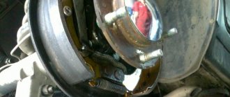
The design of the rear wheel mounting of the Chevrolet Niva is very different. However, they also use bearings that need periodic replacement. They are replaced either together with the axle shafts or separately. The second option is much cheaper, but requires good metalworking skills and a torch to heat the metal.
To work you will need:
- Jack, wheel wrench, chisel, hammer.
- Standard set of screwdrivers and wrenches.
- Axle puller.
- Gas (gasoline) burner or muffle furnace.
- Repair kit including bearing, oil seal and retaining ring.
- A pipe with a diameter of 40-45 mm, the length of which exceeds the size of the axle shaft.
Replacement of bearings is carried out as follows:
- Place the machine on a level surface.
- Place wheel chocks or bricks under the front wheels.
- Jack up the car.
- Remove the wheel.
- Place a support under the rear axle.
- Unscrew the brake drum mount.
- Dismantle the part.
- Unscrew the nuts holding the bearing.
- Load the rear axle by lowering it onto the stand.
- Pull out the axle shaft using a puller.
- Hang the brake mechanism on a wire.
- Knock down the retaining ring using a chisel, hammer and grinder.
- Crack the bearing races using a chisel.
- Remove rust and dirt from the seating surface.
- Put the new bearing in place.
- Heat the locking ring to 200-250 degrees (dark red color) and hammer it into the seat with a pipe
- Replace the oil seal.
Draining antifreeze in Chevrolet
This is the first stage that is performed when replacing a damaged Niva gasket. Initially, you need to remove the mudguard and the lubrication sump housing - they are located in the engine compartment.
- reduce the pressure in the coolant supply system by opening the cap of the distribution tank (be sure to close it afterwards - this will reduce the antifreeze pressure);
- place a container of at least 9 liters under the drain (it is under the radiator on the left);
- unscrew the cap and wait until the liquid pours out;
- inspect the gasket of the drain plug - if it is worn out, replace it too;
- Remove the cap from the expansion tank again.
Now you need to get rid of the antifreeze remaining in the cooling system of the engine itself. To the left of the cylinder head, near the ignition unit, there is a separate drain hole. Place a container under it and unscrew the plug with a 13 key.
When the liquid flows out, tighten the radiator cap and cylinder head. In the latter case, a force of at least 25 N∙m will be required.
What kind of disks can be installed?
The manufacturer recommends installing R16 standard wheels. It is allowed to mount smaller wheels R15 on the car. It’s easier to choose tires for this size; there are plenty to choose from compared to 16-inch wheels.
The depth of the body arch of the Chevrolet Niva allows the driver to install 17-inch cast wheels on the car. Correct installation of wider wheels will allow you to:
- improve directional stability and vehicle control;
- reduce braking distance in case of unexpected braking;
- increase the vehicle's maneuverability in off-road conditions.
It is worth noting the negative aspects of such a replacement:
- the likelihood of damage to the integrity of the disc increases when the tire is damaged, for example, from a side impact;
- the smoothness of the ride decreases, the movement on it becomes harsher, and vibration increases.
Removing and disassembling the cylinder head, replacing the gasket (eng) Niva VAZ 21213, 21214, 2131 lada 4×4
We remove the cylinder head to replace the gasket, repair the valve drive mechanism and the head itself, as well as when completely disassembling the engine.
To replace the head gasket or connecting rod-piston group of the engine, remove the cylinder head from the engine complete with the receiver, intake pipe and exhaust manifold.
To remove the cylinder head:
- disconnect the negative cable of the battery;
drain the coolant (see here);
remove the throttle assembly assembly (see here);
disconnect the hoses from the outlet pipe of the cooling jacket;
disconnect the hose from the heater radiator inlet pipe;
disconnect the fuel rail injector wire connector (see here);
disconnect the connectors from the coolant temperature sensor of the injection system and the coolant temperature indicator sensor;
remove the tips of the high-voltage wires from the spark plugs;
disconnect the fuel inlet and outlet pipes from the fuel rail;
disconnect the exhaust pipe from the exhaust manifold (see here), the heat shield of the starter and the bracket for the heater radiator outlet pipe (see here);
remove the camshaft and valve drive levers (see here);
remove the camshaft sprocket and tie the chain with wire.
Using a 13mm socket, unscrew the cylinder head mounting bolt located next to the ignition module bracket. |
Using a 12mm socket, unscrew the ten bolts securing the head to the cylinder block. |
We take out the bolts.
Remove the cylinder head assembly with the exhaust manifold, receiver and intake pipe with the fuel rail. |
The cylinder head can also be removed from the engine by first dismantling the receiver (see here), the intake pipe and the exhaust manifold (see here).
Remove the cylinder head without the exhaust manifold and intake pipe. |
Remove the cylinder head gasket. |
We install the cylinder head on the workbench.
Using a 10mm socket, unscrew the two nuts securing the heater radiator inlet pipe to the block head... |
...and remove it. |
Remove the sealing gasket. |
Using a 13mm socket, unscrew the two nuts securing the outlet pipe of the cooling system jacket... |
...and remove the pipe with the coolant temperature sensor of the injection system. |
Remove the sealing gasket of the pipe. |
When disassembling the valve mechanism...
...we place a stop - a wooden block - under the plate of the valve being desiccated. |
We dry out the valve (see here)…
| ...and remove the valve from the guide sleeve of the cylinder head. |
We dismantle the other valves in the same way.
We assemble and install the cylinder head in the reverse order. Before installing the valves, we clean them of carbon deposits and lubricate the valve stems with engine oil.
Having assembled the valve mechanism...
...we strike the ends of the valves with a hammer with a plastic striker for more reliable fixation of the crackers (the wooden stop must be removed from under the valve plate). |
Before installing the cooling system pipes, we clean the mating surfaces of the pipes and the block head from the remains of old gaskets.
We install new pipe gaskets, applying a thin layer of sealant to them.
We clean the mating surfaces of the head and cylinder block from the remains of the old gasket, dirt and oil.
Using a syringe with a needle or a rubber bulb, remove oil and coolant from the mounting holes of the cylinder block.
We install the gasket and cylinder head using two centering bushings. |
When installing the head on the cylinder block, we pass the chain by the wire through the hole in the head. |
Having installed the cylinder head bolts, tighten them in the order shown in the figure.
To ensure a reliable seal and eliminate the need to tighten the bolts during vehicle maintenance, tighten the bolts in four steps: 1st step – tighten bolts 1–10 with a torque of 20 N.m (2.0 kgf.m); 2nd step – tighten bolts 1–10 with a torque of 69.4–85.7 N.m (7.1– 8.7 kgf.m), and bolt 11 – with a torque of 31.4–39.1 N.m (3.2–4.60 kgf.m). Then we turn bolts 1–10 by 90° (3rd step ) and another 90° (4th move). |
Step-by-step instruction
- Initially, of course, you need to dismantle the cylinder head cover itself.
- Then place a container under the bottom of the car to collect the used refrigerant. Replacing the cylinder head cover gasket. Unscrew the drain plug and drain the antifreeze.
- Then you should disconnect the throttle cable from the receiver and assembly.
- After this, the timing pulley should be removed along with the bearing housing.
- Next, we dismantle the valve lever, and then unscrew the lever supports themselves. Also dismantle the engine fluid supply ramp to the hydraulic supports.
- Now you need to disconnect the cable harness from the TPS. In the same way, disconnect the wiring from the idle speed sensor and antifreeze.
- You need to squeeze the plastic clip and then disconnect the connector with the wires that are designed to power the injectors. Here you also need to remember to disconnect the wiring harness from the knock sensor.
- Now disconnect the high voltage cables from the spark plugs. Also disconnect the cable that powers the engine temperature control device.
- Slightly compress and disconnect the exhaust pipe from the intake manifold. Then the upper screw securing the inlet tube spacer and, slightly loosening the lower screw, the spacer should be moved to the side.
- The clamp should be loosened slightly, then the adsorber purge pipe should be disconnected from the throttle assembly.
- The clamps must be loosened and the cooling system pipes must be disconnected from the cylinder head.
- Using open-end wrenches, you now need to disconnect the fuel lines. Replacing the fuel filter on a Chevrolet Aveo with your own hands, video instructions. To do this, unscrew the nuts of the fuel hoses intended for draining and supplying gasoline.
- Now use a wrench to remove the top screw that secures the rear intake tube brace. The bottom screw should also be loosened a little. Replacing the cylinder head gasket of Peugeot 206 1.4. After these steps, the spacer must be removed to the side.
- When all the above steps have been completed, the camshaft pulley drive chain tensioner should be removed.
- Then dismantle the brackets that secure the power steering device.
- Now you can remove the chain with the timing pulley star.
- After this, using a socket with an extension, you will need to unscrew the screws securing the cylinder head, and then dismantle it.
- Now you can remove the cylinder head gasket. Mount a new component in its place, having previously lubricated its perimeter with sealed glue. Actually, at this point the work on replacing the cylinder head gasket in the Chevrolet Niva can be considered completed. All further work on assembling the power unit must be performed in the reverse order. How to replace the cylinder head gasket on video 3 from the Niva Chevrolet cylinder head. But that is not all. To ensure a reliable fit of the cylinder head to the block itself, you need to correctly tighten the screws and maintain the tightening torque.
- The procedure itself consists of several stages. First of all, using a torque wrench and following the order indicated in the diagram, you need to tighten the screws from the first to the tenth. In this case, the tightening torque of the Niva Chevrolet cylinder head should be 20 Nm.
- Next, when all the bolts are tightened in turn, you need to tighten all the cylinder head screws again. The tightening torque should now be 69.4–85.7 Nm. The last, eleventh pulley needs to be tightened to 31.4–39.1 Nm.
- After these steps, the screws marked with numbers from one to ten need to be turned 90 degrees, and then, when they are all screwed, you should repeat the procedure and turn them again 90 degrees. At this point, the screw tightening procedure can be considered complete.
Read news about the new Niva
- No longer Chevrolet: Lada Niva returns - Autoreview
- Chevrolet Niva 2022 ALREADY IN RUSSIA! new body configuration and prices photo, video test drive
- The Chevrolet Niva with the face of Vesta will appear in 2022. Photo
- New Niva Chevrolet Lux 2022
- Production of the restyled Chevrolet Niva 2022 has started [photo]
- Lada Niva 2022 new body | Lada Niva Chevrolet prices and specifications for 2022 from an official dealer.
- Rear left wheel speed sensor (ABS) on Chevrolet Niva (VAZ 2123) | Motorring online store
- How to adjust the clutch on a Chevy Niva
Also interesting: Renault Duster and Chevrolet Niva - video tests
Chevrolet Niva hub malfunctions
Most wheel hub repairs involve replacing the wheel bearing. Less often, the hub itself fails, since the material from which it is made is quite durable. The reason for replacing the wheel bearing is simple wear. It is necessary to understand that there is a huge load on it, because the distributed load from the car itself exerts pressure from above. When driving over uneven surfaces, this load increases. If we also take into account the mobility of the bearing parts, the reason for the wear that appears on the inner and outer race will become clear. A failed wheel bearing begins to emit extraneous noise, which intensifies over time.
There are two simple ways to diagnose a bad wheel bearing. The first is that on an empty highway you need to drive along a large radius curve, first in one direction and then in the other. In simple words, when driving, you first need to turn the steering wheel slightly to the right, and then to the left. Typically, bearing noise will increase in one case and then decrease. If the noise increases when you turn the steering wheel to the right, then the reason is in the left bearing and vice versa.
You can finally verify that the bearing is faulty by hanging the wheel. It will make some noise when rotating. When vibrations occur relative to the horizontal axis, play may occur. To detect this play, it is necessary to apply force to the upper and lower points of the wheel.
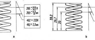
Niva cylinder head bolts, installation
To work with bolts, a special tool is required. E16 head, which is not always included in universal tool kits, and a torque wrench. To make the process logically complete, the price list includes an E16 head (Sata or Force) and a torque wrench (JTK).
I won’t invent anything about the installation technology, just completely follow the factory manual.
- Submerge the bolts in a container of engine oil.
- Let it drain. Exposure for at least 30 minutes.
- Wrap and tighten according to the diagram.
Stage 1 – tightening with torque (12…20) N.m;
Stage 2 – tightening torque (50...70) N.m;
Stage 3 – turning the bolts by 90-110 degrees;
Stage 4 – turning the bolts 90-110 degrees.
Tightening torque of bolt 11 (at the cylinder head tail): preliminary – (14…16) N.m; final – (32…40) N.m.
Engine control system VAZ-Scheme
21214 connections of the engine management system 21214-VAZ with central fuel injection under US-83 toxicity standards with controller 21214-1411010 (EFI type-4) on VAZ-21214 cars: 1 - control lamp “CHECK ENGINE”; 2 — instrument cluster (electric fans); 3 — fragments of the engine cooling system*;
4 — electric heater of the inlet pipe; 5 — air temperature sensor; 6 — absolute pressure sensor; 7 — coolant temperature sensor; 8 - connectable block to the throttle position sensor; 9 — central fuel injection unit; 10 — block connected to the idle speed regulator;
11 — block attached to the block; 12 — diagnostic nozzle; 13 - controller; 14 — knock sensor; 15 — speed sensor; 16 — oxygen concentration sensor; 17 - adsorber; 18 — battery container; 19 - main relay; 20 — engine control fuse block; 21 - relay switch on;
22 — electric fuel pump for turning on the electric fan*; 23 — relay for turning on the inlet electric pipe heater; 24 — electric protection fuse; 25 — starter heater; 26 — ignition relay; 27 — car main fuse block (fragment); 28 — spark plugs tachometer; 29 — ignition; 30 — electric fuel pump with fuel level sensor;
31 — ignition module; 32 — crankshaft position sensor; 33 — courtesy light switch located on the driver's door pillar; 34 — control unit of the automobile anti-theft system**; 35 — status indicator of the car anti-theft system**; A - wire to the plug going “50” of the ignition switch;
The numbering order of the conventional plugs in the blocks is: a - controller; b — car control unit of the anti-theft system; c — indicator of the state of the anti-theft vehicle system; g — speed sensor; d — central fuel injection unit; e — electric fuel pump and module concentration sensor; g - ignition oxygen; h - absolute pressure sensor.
connections Scheme of the VAZ engine management system - distributed with 21214 fuel injection under Euro toxicity-2 standards with controller 2123-1411020-10 (MP 7.0 type) on VAZ-21214 cars: 1 - control lamp for the engine control system; 2 — instrument cluster (fragments); 3 — electric fans for engine cooling;
4 — lamp switch, pillar located on the driver’s door; 5 — status indicator of the vehicle anti-theft system; 6 — control unit of the anti-theft vehicle system; 7-cooling temperature sensor; 8 - air flow fluid; 9 — throttle assembly; 10 — connectable block to the throttle position sensor;
11 — block connected to the idle speed regulator; 12 - controller; 13 — oxygen concentration sensor; 14 - sensor sensor; 15 — crank position sensor; 16 — speed shaft; 17 - adsorber; 18 — battery; 19 — main relay; 20 — diagnostic block; 21 — engine control fuse block;
22 — relay for switching on socaelectrobenzone; 23 — relay for turning on electric fans; 24 — main fuse block of the car (fragment); 25 — block, connected to the additional wiring harness*; 26 — ignition module; 27- electric fuel pump; 28 — tachometer with fuel level sensor; 29 — nozzles;
30 - lighting the candle; A - wire of the rear wiring harness, connected to the switch 4; B - wires connected to plug “1” of fuses of block 24 (one wire goes to plug “15” of the ignition switch, and the other to plug “85” of the ignition relay); B - rear wires of the wiring harness, connected to the fuel level indicator.
The order of conditional numbering of plugs in the controller: a - pads; b — control unit for automobile anti-theft sensors; in - air flow system; g — speed sensor; d — status of the car anti-theft system indicator; e - electric sensor and robin pump for oxygen concentration; g - throttle pipe; h — module ignition.
Tightening torques for threaded connections of a Gazelle car
To maintain the exact torque of critical threaded connections, you need to have a torque wrench with a measurement range of 5 to 200 Nm.
Tightening torques for threaded connections
| Connection name | Moments tightening kgf•m |
| Spark plug | 3,0–3,5 |
| Cylinder head nuts | 8,3–9,0 |
| Nuts securing connecting rod bolts | 6,8–7,5 |
| Main bearing cap nuts | 10,0–11,0 |
| Flywheel nuts | 7,6–8,3 |
| Nuts securing the clutch housing to the cylinder block | 2,8–3,6 |
| Crankshaft bolt | 17–22 |
| Clutch pressure plate mounting bolts | 2,0–2,5 |
| Nuts for securing the intake manifold and exhaust manifold | 1,5–3,0 |
| Oil pan fastening nuts | 1,2–2,0 |
| Cylinder head bolts: pre-tightening final tightening | 4,0–6,0 13,0–14,5 |
| Nuts securing connecting rod bolts | 6,8–7,5 |
| Main bearing cap bolts | 10,0–11,0 |
| Flywheel mounting bolts | 7,2–8,0 |
| Clutch housing mounting bolts | 4,2–5,1 |
| Crankshaft bolt | 10,4–12,0 |
| Clutch pressure plate mounting bolts | 2,0–2,5 |
| Camshaft cover bolts | 1,9–2,3 |
| Camshaft sprocket mounting bolts | 5,6–6,2 |
| Valve cover bolts | 0,5–0,8 |
| Intake pipe mounting nuts, Clutch housing booster mounting bolts | 2,9–3,6 |
| Coolant pump pulley mounting bolts, front cylinder head cover, circuit covers, thermostat housing | 2,2–2,7 |
| Bolts for securing the oil seal holder, oil pan | 1,2–1,8 |
| Exhaust manifold mounting nuts | 2,0–2,5 |
| Main bearing cap nuts | 12,5–13,6 |
| Nuts of connecting rod cap bolts | 6,8–7,5 |
| Nuts of connecting rod cap bolts | 6,8–7,5 |
| Nuts for fastening the rocker arm axle struts | 3,5–4,0 |
| Oil filter mounting fitting | 8,0–9,0 |
| Oil filter | 2,0–2,5 |
| Transfer case shaft flange nuts* | 20–28 |
| Transmission housing mounting bolts | 1,4–1,8 |
| Front and rear crankcase mounting bolts and transfer case covers* | 1,2–1,8 |
| Nuts securing the cardan transmission to the transfer case*, front* and rear axles | 2,7–3,0 |
| Rear propeller shaft spline yoke mounting bolt** | 5,0–5,6 |
| Nuts for fastening the drive flanges of the front axle* | 11–12,5 |
| Steering arm mounting nuts* | 11–12,5 |
| Trunnion mounting nuts* | 11–12,5 |
| Rear axle gearbox bolts with banjo beam | 5,5–7,0 |
| Nut securing the drive gear flange of the front and rear axles | 16,0–20,0 |
| Bolts for tightening rubber-metal bushings | 12,0–15,0 |
| Spring ladder nuts | 12,0–15,0 |
| Shock Absorber Reservoir Nuts | 9,0–15,0 |
| Wheel nuts | 30,0–38,0 |
| Kingpin locking pin nuts* | 3,2–3,6 |
| Nuts for fastening ball joints of steering rods | 7,0–10,0 |
| Bolts securing the steering arms to the steering knuckles | 11,0–12,5 |
| Tie Rod Clamp Bolts | 1,4–1,8 |
| Nuts securing the steering gear bracket to the side member | 2,8–3,6 |
| Bolts securing the steering gear to the bracket | 4,4–6,2 |
| Steering wheel nut | 6,5–8,0 |
| Bipod fastening nut | 10,5–14,0 |
| Nuts for fastening wedges of cardan forks | 1,8–2,5 |
| Bolts securing brake calipers to steering knuckles | 10,0–12,5 |
| Brake shield mounting bolts | 5,0–6,2 |
| Wheel cylinder bolts | 1,4–2,0 |
| Nuts securing the master cylinder to the vacuum booster | 2,4–3,6 |
| Vacuum booster mounting nuts | 1,2–1,7 |
| Nuts for elastic fastening points of the body to the frame | 3,1–3,9 * |
For 4x4 vehicles; **for 4x2 vehicles
Cylinder head tightening torque for VAZ-2112 16 valves (Prior)
The tightening torque of the cylinder head on the Prior is taken from the vehicle’s operating manual and is indicated in plate No. 2.
Install the head on the block first, making sure that the crankshaft and camshafts are in the TDC position (both valves of the 1st cylinder must be closed). Tighten the block head bolts in the sequence shown in Fig. 5.6, in four stages: 1st – torque 20 N·m (2 kgf·m); 2nd – torque 69.4–85.7 N m (7.1–8.7 kgf m); 3rd – tighten the bolts by 90°; 4th – finally tighten the bolts 90°.
| Detail | Moment | Tightening thread, Nm (kgf*m) |
| Cylinder head block bolts | M12x1.25 | 1st - torque 20 Nm (2 kgf*m); 2nd - kgf 69.4-85.7 Nm (7.1-8.7 torque*m); 3rd - tighten the bolts 90°; 4th - finally tighten the Bolt 90°. |
| cylinder head cover bolts Bolt | M6 | 1.96-4,60 (0,20-0.47) |
| cylinder head mounting | M8 | 31,36-39,10(3,20-3,99) |
Table No. 2. tightening Torque of the cylinder head (cylinder head) Necessary.
Prior to consider that:
The cylinder head block bolts are pulled out when the bolts are repeated. used, the length of which (excluding the height head) exceeds 98 mm, replace with new ones. Before installing the head block, lubricate the bolts with a thin layer of engine oil.
Removing the cylinder head
VAZ 2107 1982+: Appendix 1. tightening torques of threaded connections* VAZ 2107 Lada
How to remove the cylinder head is described in detail in the vehicle's operating instructions, so here we will only briefly describe the general procedure for performing this work. Typically this operation is performed as follows:
- Place the car on a level surface, secure it with the hand brake, set the gear shift lever to neutral;
- Disconnect the ground wire (negative) from the battery;
- Using the marks on the pulleys (or gears) and the engine, set the first cylinder to TDC (on new models, for this you must first unscrew the timing drive protective cover);
- Drain the engine coolant;
- Disconnect all wires connected to the cylinder head - spark plug armor wires, sensor wires, ground terminals, etc.;
- Disconnect the cooling system pipes, fuel hose and other pipes from the cylinder head;
- On some models - unscrew the distributor, generator and other parts;
- Free the carburetor or throttle assembly from pipes, wires, cables and other parts;
- Unscrew the muffler exhaust pipe from the exhaust manifold;
- Using a special tool, remove gears, tension rollers and other timing drive parts;
- Remove the cylinder head cover;
- Unscrew the ten bolts securing the head to the block;
- Remove the cylinder head.
Now you can replace the gasket or repair the head, for which the intake and exhaust manifolds are unscrewed from it, and it is disassembled further (the valves are cracked and removed, the camshaft is removed, etc.). But in any case, the removed head must be thoroughly inspected and its condition checked, as described below.
It is necessary to pay attention to two very important points. Firstly, the head bolts must be unscrewed in a certain order and according to a certain pattern
Typically, unscrewing begins with the central bolts, and the outer bolts are unscrewed last, and first all the bolts must be loosened (no more than one turn), and only then completely unscrewed.
Secondly, removal of the block head must be done very carefully so as not to damage it, especially its lower (matting) surface. Therefore, when removing the cylinder head, you should never pry it with a screwdriver or other tools; it is better to move the head to the side and then lift it with your hands. In some engines, you can lift the head using an improvised lever from a screwdriver placed under the exhaust manifold.
The removed head must be placed only with the bottom side on smooth and clean wooden blocks - this will prevent the bottom part from scratches and deformations. And, of course, under no circumstances should you throw the head, as if it falls, it can be seriously damaged and will be unsuitable for further use.