Ignition systems for gasoline engines of domestic passenger cars VAZ-2108, VAZ-2109, ZAZ-1102 contain an electronic switch. It is designed to generate current pulses in the circuit of the primary winding of the ignition coil.
In domestically produced electronic switches (series 3620.3734; 36.3734; 78.3734), the functions of the output current switch are performed by a powerful transistor, and the functions of controlling the parameters of current pulses (normalizing the duty cycle of triggering pulses, software regulation of the time of energy accumulation in the ignition coil, limiting the current level in its primary winding and amplitude of primary voltage pulses) is performed by a low-current electronic circuit, often in an integrated design.
The first domestic electronic switch with controlled parameters of ignition pulses (series 36.3734) was developed for the VAZ-2108 car. The switch used the K1401UD1 microcircuit, a powerful key transistor KT848A and other domestically produced elements.
The input information signal for the switch is the signal from the Hall sensor located on the ignition distributor shaft. Using this signal, the switch receives information about the number of engine revolutions and the position of its crankshaft. The switch is designed to work with a serial ignition coil 27.3705.
The switch was a prototype for the development of subsequent series, which have several design and circuit design options. However, what domestic switches still have in common is a combined integrated-discrete assembly technology, which makes them repairable.
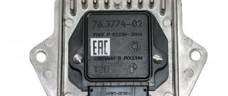
Modern domestic switches use specialized output key transistors of the types KT890A, KT898A1, BU931 (foreign) in several designs: TO-220, TO-3, unpackaged. Some switches, for example 78.3734 (Fig. 4), use a four-channel operational amplifier of the K1401UD2B type as a control chip.
The switches also widely use the L497B control chip from SGS-TOMSON (domestic analogue of the P1055HP1). The block diagram and the recommended option for its inclusion are shown in Fig. 1, and the assignment of the pins is in table. 1.
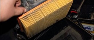
Before you begin troubleshooting and repairing the electronic switch, you should: • check the integrity of the vehicle wiring, the reliability of the contact connections of the ignition system, the serviceability of the ignition system elements (spark plugs, ignition coil, Hall sensor, high voltage wires); • check the serviceability of the car generator, as well as its integrated voltage regulator; • check the supply of voltage from the on-board network (with the ignition switch on) to contact “P” of the Hall sensor connector.
The signs that indicate malfunctions of electronic switches, the most likely causes of these malfunctions and methods for eliminating them are summarized in table. 2.
Schematic diagrams of the ignition switches are shown in Fig. 2 (switch 3620.3734 – I), fig. 3 (switch 3620.3734 - II) and fig. 4 (switch 78.3734).
In conclusion, the following should be noted:
1. A close analogue of the foreign transistor BU931 (see diagrams in Fig. 2 and 3) is the domestic KT898A1. These transistors have a wide range of parameters, which leads to the need to select the ratings of radio elements in its base and emitter circuits for each individual transistor.
2. Resistors R7 (see Fig. 2) and R6 (see Fig. 3) are used to set the required current value through the powerful key transistors of the described switches.
Increasing the resistor value leads to a decrease in current and vice versa. Thus, by changing the values of these resistors, you can select the optimal current and thermal operating conditions of the output key transistors.
3. When replacing a powerful switching transistor, you should pay attention to the quality of fastening the transistor to the radiator (case) of the switch. They also check the presence of heat-conducting paste between the transistor and the radiator (switch housing).
4. An analogue of the foreign zener diode 1N3029 (see Fig. 3) is the domestic KS524.
5. An analogue of the foreign microcircuit L497B (see Fig. 1, 2, 3) is the domestic KR1055ХП1.
6. After replacing faulty radio elements in the switch, each new element on the board and its soldering area should be coated with nitro varnish. When assembling the switch housing, its cover around the perimeter of the seal must be coated with a waterproof sealant (for example, Germesil).
The switch is an electronic component to ensure the operation of a contactless ignition system. It is transitional between contact and microprocessor. The latter, the most advanced, allows you to control the torque using data read from sensors - oxygen, speed, engine speed and others. But there are still many cars on the roads that have both contact breakers and contactless ones. Therefore, for maintenance and diagnostics, you need to know the purpose of all elements, as well as troubleshooting methods and their main symptoms. Before testing the switch, review all parts carefully.
Contactless ignition system
In total, there are three huge groups of systems - contact, contactless, microprocessor. The first is divided into two subgroups - contact and using a transistor operating in switch mode. Transistors are also used in the design of a contactless ignition system. This scheme began to be actively used in the early 80s of the last century. And it has a number of advantages, which will be discussed below. The switch circuit is simple; it can be implemented both on transistors and on a controller.
But the contactless ignition system also has many disadvantages when compared with a microprocessor one. The latter allows you to control almost all engine parameters. BSZ does not allow this; it also cannot be used normally on injection engines. The reason for the obsolescence of the contactless system lies not only in the development of electronics and the automotive industry, but also in the adoption of stringent measures to ensure the environmental friendliness of internal combustion engines. Unfortunately, only microprocessor control can reduce the amount of harmful substances in the exhaust.
Types of sanitary protection
The ignition system serves to ignite the air-fuel mixture located in the engine cylinders at the required moment.
The applied protection systems can be divided into three main types:
- Contact;
- Contactless;
- Contact transistor.
The first and third types are not of particular interest to us, since the VAZ 2109 uses a contactless or contactless transistor system.
The use of such schemes began in the mid-80s of the last century. Over time, engineers have been able to improve efficiency, performance and reliability.
Operating principle
The operating principle of the ignition system installed on the VAZ 2109 is as follows:
- The crankshaft position sensor performs its main tasks, sending a signal to the controllers;
- The controller processes the received information and calculates the sequence of switching on the ignition coils;
- The coil creates two sparks - igniting and idle.
The dry spark method involves creating sparks simultaneously in two spark plugs. One is igniting, and the second is idle, because it beats in time with the release of exhaust gases on the other spark plug. Thus, the cylinders where sparks are generated simultaneously create pairs - cylinders 1 and 4 and cylinders 2 and 3.
Coil
Main advantages
The ignition system used for nines has good reliability indicators, although it produces energy up to 50 kJ, and the breakdown voltage can sometimes reach 30 kV or more. BSZ is valued for its high efficiency.
There are several main advantages that characterize contactless ignition systems.
Advantages
Peculiarities
SZ works with a Hall sensor
Because of this, the spark energy parameters are not affected by the voltage in the electrical network or the frequency of the engine. This is due to the fact that the time period of energy concentration in the ignition coil is always constant. This ensures high efficiency of the circuit
There is no mechanical interaction between contacts
This ensures there is no contamination or burning of contacts, so there is no need to clean them
No need to adjust the position of the contacts
This can be explained simply - they are not in the SZ VAZ 2109
Minimal mechanical interactions between parts
This factor contributes to the absence of rotor vibrations, resonance, and uneven spark distribution across the spark plugs
The energy in the candles is constantly increased
It can reach 50 J, which allows you to avoid failures when igniting the air-fuel mixture in the cylinders. This is especially noticeable when accelerating a car.
Cost-effective and environmentally friendly
The use of the new SZ made it possible to improve fuel economy by approximately 5 percent, as well as reduce CO emissions by 20 percent
Stable cold engine start
Even if the battery is discharged to 6V, you can still start the engine without problems. This makes BSZ significantly different from other ignition systems that cannot boast of such stability.
Scheme
Main elements of the system
Of course, the first thing to mention is the spark plugs. They are installed in the cylinder head, the electrodes come out from the inside. These are the elements that allow the air-fuel mixture to ignite. But with the help of spark plugs alone, the engine will not be able to run. It is necessary to monitor the position of the crankshaft in order to know in what position the pistons are in the cylinders.
For this purpose, an inductive sensor operating on the Hall effect is used. It is part of the design of another element - the ignition distributor. The sensor produces a pulse that is sent to the switch. This device allows you to amplify a weak signal to a voltage of 12 volts, and then apply it to a coil. A coil is nothing more than a simple transformer (step-up). Its secondary winding has a greater number of turns than the primary. Due to this, the voltage increases and the current decreases. The voltage in the BSZ is supplied to the spark plugs at a value of 30-35 kV (depending on the car model).
Video on repairing KZ VAZ
Every owner of the VAZ 2109 should know the ignition circuit Without knowing this circuit, you will not be able to start the car in case of ignition problems. Moreover, this scheme is elementary simple. The VAZ 2109 is equipped with a contactless ignition system. It consists of the following components: switch, ignition coil, distributor, Hall sensor, high-voltage wires and spark plugs. The task of the ignition system is to provide a timely, cyclic spark to the engine cylinders. Let's take a closer look at how the clamping circuit works.
Ignition circuit for VAZ 2109
ignition of the VAZ 2109: power is supplied to the ignition system through a relay. Until the key is in the ignition position, the relay will not turn on and supply power to the circuit. As soon as the key is turned, the ignition system is energized. +12V power from the battery is supplied to contact B of the ignition coil, the 4th contact of the switch. The Hall sensor powers the switch itself. Please note that the ignition relay is powered through the mounting block, and if there is poor contact in connectors Ш1, Ш8 or for some reason the track oxidizes or burns out, the ignition system will not be powered and the VAZ 2109 will not start. In order for a spark to begin to form, you need to crank the engine crankshaft. Together with it, the camshaft will turn and the Hall sensor will send an impulse to the switch. The commutator, in turn, will connect contact K of the ignition coil to ground, resulting in a spark appearing on the central wire. When the distributor slider connects the central wire and the wire leading to a specific engine cylinder, a spark will jump on the spark plug, igniting the combustible mixture. The engine will start. When it is necessary to turn off the engine, the driver, by turning the key in the ignition switch, turns off the relay, which in turn disassembles the power supply to the system. The switch and ignition coil become de-energized and stop working. The most common malfunctions of the VAZ 2109 ignition system: 1) Failure of the switch. 2) Failure of the Hall sensor. 3) Poor contact of the slider in the distributor. 4) Lack of power supply to the ignition system of the VAZ 2109. Go to Home.
How is BSZ better than contact?
Having carefully read the previous section, you can see that the system uses an inductive non-contact Hall sensor. The advantage is obvious - there is no friction and commutation. For comparison, look at the contact system. In it, the breaker switches the voltage, the value of which is 12 Volts. Whatever one may say, the metal contacts are constantly in contact with each other, gradually wear out, and become covered with soot.
For these reasons, it is necessary to constantly monitor the breaker, adjust the gap, and carry out timely replacement. BSZ is devoid of these shortcomings, therefore, without third-party intervention, the system operates much longer. The Hall sensor fails very rarely, as does the switch. This increases the reliability of the system, but precautions must also be taken, in particular, the connection of the switch to the body must be as tight as possible to ensure effective heat exchange. In addition, BSZ allows you to improve engine performance, increase, albeit slightly, its power, along with increasing reliability.
Instructions for display
There are several options for adjusting the ignition on a figure-eight engine, all of them are described in detail in this article. But now we would like to talk about how to set the ignition on a VAZ and how to check the set angle using a special device. Namely, we are talking about the emergency ignition module.
So, the ignition installation is carried out as follows:
- First of all, the connector should be removed from the switch.
- After this, the emergency ignition must be installed in the connector, the key must be turned, but the starter should not be rotated.
- Next, the hood opens, you need to align the crankshaft mark with the camshaft mark. Use the service book and follow the recommendations noted in it.
- There is a diode D on the emergency ignition, with its help the required angle is set, in particular, at the moment when the light comes on. The angle is set by rotating the camshaft, while the slider on the distributor cover must be directed towards the first cylinder.
How does a switch work?
Essentially, a switch is a simple signal amplifier. It can even be compared to a Darlington assembly, which is used in microcontroller technology to convert a weak signal from an output port to the required level. The basis of this assembly is field-effect transistors operating in switch mode. An operating voltage is applied to them, a signal is sent to the control terminal, which is amplified and removed from the collector.
The ignition switch has an almost similar operating scheme. Only the signal from the Hall sensor is used. It has three outputs - control, common, plus power. When a metal plate appears in the sensor area, a current is generated, which is supplied to the input of the switch. Next, the signal is amplified and supplied to the primary winding of the coil. The entire system is powered only after the ignition is turned on (after turning the key).
Techno lovers site
Since an idea appeared on the Internet about the possibility of using the 3620.3734* switch instead of the standard Tavria 1102.3734/1103.3734, I decided to post an article on repairing them, along with the diagrams of these switches. The original article is here, but for some reason the developer of this web page posted the pictures separately from the article. It’s very inconvenient, I’ll translate it in human terms:
When the electronic ignition switch in your car fails, as a rule, you either buy a new one, since there is no way to check its functionality due to the lack of specialized service centers, or take it to local craftsmen who try it using the “scientific poke” method repair. Most operating instructions do not contain a description of the troubleshooting technique, so we provide a complete troubleshooting technique and circuit diagrams of the most common electronic ignition switches.
Ignition systems for gasoline engines of domestic passenger cars VAZ-2108, VAZ-2109, ZAZ-1102 contain an electronic switch. It is designed to generate current pulses in the circuit of the primary winding of the ignition coil.
In domestically produced electronic switches (series 3620.3734; 36.3734; 78.3734), the functions of the output current switch are performed by a powerful transistor, and the functions of controlling the parameters of current pulses (normalizing the duty cycle of triggering pulses, software regulation of the time of energy accumulation in the ignition coil, limiting the current level in its primary winding and amplitude of primary voltage pulses) is performed by a low-current electronic circuit, often in an integrated design.
The first domestic electronic switch with controlled parameters of ignition pulses (series 36.3734) was developed for the VAZ-2108 car. The switch used the K1401UD1 microcircuit, a powerful key transistor KT848A and other domestically produced elements.
The input information signal for the switch is the signal from the Hall sensor located on the ignition distributor shaft. Using this signal, the switch receives information about the number of engine revolutions and the position of its crankshaft. The switch is designed to work with a serial ignition coil 27.3705. The switch was a prototype for the development of subsequent series, which have several design and circuit design options. However, what domestic switches still have in common is a combined integrated-discrete assembly technology, which makes them repairable.
Modern domestic switches use specialized output key transistors of the types KT890A, KT898A1, BU931 (foreign) in several designs: TO-220, TO-3, unpackaged. Some switches, for example 78.3734 (Fig. 4), use a four-channel operational amplifier of the K1401UD2B type as a control chip.
The switches also widely use the L497B control chip from SGS-TOMSON (domestic analogue of the P1055HP1). The block diagram and the recommended option for its inclusion are shown in Fig. 1, and the assignment of the pins is in table. 1.
Control chip L497B from SGS-TOMSON (domestic analogue of P1055ХП1). Block diagram and recommended option for its inclusion.
| Pin no. | Purpose | Pin no. | Purpose |
| 1 | General | 9 | Terminal for connecting the capacitor to the protection unit |
| 2 | General (signal) | 10 | Pin for connecting a storage capacitor to the delay control circuit |
| 3 | Meal 1 | 11 | Pin for connecting the correction capacitor to the delay control circuit |
| 4 | Not used | 12 | Pin for connecting an external voltage reference resistor |
| 5 | Hall sensor signal input | 13 | Current limiter input |
| 6 | Pulse Width Modulator Output | 14 | Output signal for driving an external transistor |
| 7 | Output for connecting an additional zener diode | 15 | Output pulse amplitude limiter input |
| 8 | Output for connecting the driver time constant correction capacitor | 16 | Power supply 2 (output stage) |
Before you begin troubleshooting and repairing the electronic switch, you should:
- check the integrity of the vehicle wiring, the reliability of the contact connections of the ignition system, the serviceability of the ignition system elements (spark plugs, ignition coil, Hall sensor, high voltage wires);
- check the serviceability of the car generator, as well as its integrated voltage regulator;
- check the supply of voltage from the on-board network (with the ignition switch on) to contact “P” of the Hall sensor connector.
The signs that indicate malfunctions of electronic switches, the most likely causes of these malfunctions and methods for eliminating them are summarized in table. 2.
Basic Switch Elements
The switch circuit is quite simple, but making this unit yourself is pointless, since buying a ready-made version will be much easier. Installation must be carried out as competently as possible, otherwise the device will not operate correctly. In addition, when using transistors, you need to carefully select them according to their parameters, and for this you need to have high-quality measuring equipment. Unfortunately, for two identical semiconductors, the spread of characteristics can be very large. And this affects the operation of the device.
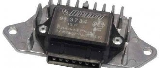
The VAZ switch, designated 76.3734, consists of one main element - the L497 controller. It is designed specifically for use in contactless ignition systems. The domestic analogue of this controller is KR1055HP2. Their parameters are almost identical, which allows you to use any of the controllers. In addition, this chip allows you to connect a tachometer located on the dashboard of the car. But you can also use a simpler circuit, which is an amplifier unit of two stages. True, the reliability of such a device is much lower.
Ignition switch
When electrical components appeared in the design of the first cars, the combustible mixture was ignited using batteries. This system had a primitive design, which has undergone significant modernization in modern cars. The essence of the operation of such devices is to create a spark inside the combustion chamber, which leads to a further chain reaction of fuel combustion in the cylinders. The method of operation of these systems is based on the principle of self-induction. The magnetic coil converts low voltage to high voltage. Current flows through a closed circuit, and when it breaks, a spark appears on the spark plug.
The same principle of operation is used in ignition systems on domestic cars. The main differences between modern systems are the new element base, changes in certain parts and the addition of switches. It is a special device that is connected to the power circuit of the primary winding of the coil. The switch performs the function of adjusting pulses and, upon a signal from the control unit, interrupts the power supply, which leads to a spark.
Connecting the switch
Cases vary, and it is possible that you will have to change the wiring. Therefore, you will need to take into account the purpose of all pins on the switch plug. This will allow the connection to be made correctly, and there will be no risk of damaging it. The first pin of the switch is the output. In other words, the amplified signal is removed from it. It must be connected to the terminal of the “K” coil. The second contact is connected to ground - the negative of the battery.
All three wires from the Hall sensor go to the VAZ switch. Moreover, the signal wire is connected to the sixth terminal of the switch. The fifth is the power output (the voltage on it is stable 12 Volts). The third output of the switch is ground (minus power). The third is connected inside the block to the second. But between the fourth, which is supplied with power from the battery, and the fifth there is a constant resistance and a voltage stabilizer.
What signs indicate a faulty switch?
The most obvious sign of a faulty switch is the loss of the so-called spark, as well as interruptions in the operation of the engine, for example, it may begin to have difficulty starting and quickly stall even after warming up.
It is not recommended to immediately change the switch due to loss of spark, since such a malfunction is sometimes caused by other automotive components that fail:
- Hall Sensor;
- timing belt rupture;
- poor contact in the distributor;
- ignition coil failure. If a malfunction is detected in this particular element, then, according to experts, the coil needs to be replaced rather than wasting time on repairing it.
If diagnostics of the components described above confirm their serviceability, you will have to begin checking a more complex device called a switch.
How to check
There is nothing complicated in this procedure. The easiest way is to use a known-good node, since you can check the switch this way in literally a matter of minutes. But if there is none, and you need to determine exactly whether the fault is in the coil or in the switch, it is wiser to use other methods. You will need a simple incandescent lamp. If you don’t know where to get it, then unscrew it from the interior lamp or from the side lights.
Connect one terminal of the lamp to the negative of the battery. Connect the second one to pin “1” of the switch. This is the same pin from which the amplified signal is removed. If the lamp lights up, then the device is working properly. A more advanced testing method is carried out using an oscilloscope. On the screen you can see the magnitude and shape of the signal, and also compare it with the reference one.
SZ scheme
The ignition system used on the VAZ 2109 includes the following components:
- Switch;
- Candles;
- Distributor sensor;
- Ignition coils;
- Switch;
- Locking device. It does not allow the starter to turn on until the ignition is completely turned off;
- Locking and anti-theft device;
- Hall Sensor;
- The sensor-distributor roller, which is located horizontally and receives torque from the camshaft;
- System of spontaneous ignition shutdown, which is activated after 2-8 seconds;
- Switched current equalization system, which is required when the network voltage changes within the range of 6-18V;
- The system built into the switch, which regulates the time of energy accumulation in the coil, limits the current strength at low motor operating frequencies.
The ignition system operates with a voltage of up to 26 kV, the spark charge has a duration of 1.6-2.0 milliseconds, and the energy released during this time is 35-50 MJ.
Service
If you do not monitor the state of the system and lose sight of the presence of malfunctions and malfunctions, this can lead to certain consequences. Namely:
- Reduced reliability of the operation of the protective equipment, the occurrence of failures;
- Reduced technical characteristics of the engine, such as acceleration dynamics, maximum speed;
- A sharp increase in the amount of fuel consumed;
- Failure of SZ elements or the entire system.
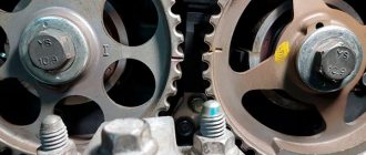
Ignition settings
When setting up the ignition, you will need to do the most important thing - install the shafts according to the marks so that the gas distribution functions synchronously with the operation of the piston group. This is the first thing you should do before you start adjusting the ignition. It is worth noting that there should not be any particular difficulties during setup, especially on VAZ 2108-21099 cars. The thing is that the ignition distributor on the engines of these machines can only be installed in one position. Moreover, the ignition switch does not undergo any settings during this procedure, since it does not have any.
The distributor body rotates around its axis to make more precise adjustments. And this turns out to be enough. To accurately set the torque, you can use a simple circuit that uses a simple LED as an indicator. The Hall sensor is disconnected from the system, and positive power is supplied to its negative terminal. An LED is switched on between “+” and the signal LED, and a 2 kOhm resistance is connected in series with it to reduce the voltage. But the plus of the Hall sensor is connected to ground. Now all that remains is to slowly rotate the distributor housing. The moment when the diode lights up will be the desired one.
What is and what is the principle of operation of the ignition switch
Even on the very first cars, battery ignition systems were used to ignite the combustible mixture, the functional diagram of which is shown in the figure.
This figure allows you to understand that its work is based on the principle of self-induction. When the current flow circuit in the winding of bobbin 3 is broken, a high-voltage EMF is induced in the secondary, causing a spark to appear on the contacts of spark plug 2. The circuit break is caused by the opening of the contacts of breaker 6.
Without touching on the advantages or disadvantages, it should be noted that this scheme worked on the car for a long time. And only the emergence of a new element base gave impetus to the further development of such a device, preserving the original principle of its operation.
conclusions
Many advantages are provided by such a simple unit in a contactless ignition system as a switch. This includes an increase in power, even if only slightly, a reduction in fuel consumption, and a significant improvement in the engine in terms of reliability. And most importantly, there is no need for constant monitoring and timely adjustment of the system. The modern driver does not want to repair a car, he needs a means of transportation. Moreover, it is reliable and will not let you down at the most crucial moment. Regardless of which switch is used in the BSZ, its efficiency is much higher than that of a contact breaker.
The VAZ 2108 switch provides the formation of control pulses supplied to the ignition coil. This element of the vehicle's electrical equipment is an electronic device that ensures the normal functioning of the vehicle's contactless ignition system.
This component of the vehicle's electronic ignition system is surface mounted and is robust enough to withstand the high vibration and shock loads that may occur during vehicle operation. The device implements the maximum possible protection options for electronic components.
Pinout and diagram of the VAZ ignition coil
Pinout of ignition coil modules for various car models of the VAZ family:
Ignition VAZ 2101
1 – generator; 2 – ignition switch; 3 – ignition distributor; 4 – breaker cam; 5 – spark plugs; 6 – ignition coil; 7 – battery.
Ignition VAZ 2106
1 – ignition switch; 2 – fuse and relay block; 3 – EPHH control unit; 4 – generator; 5 – solenoid valve; 6 – microswitch; 7 – spark plugs; 8 – ignition distributor; 9 – ignition coil; 10 – battery.
Ignition VAZ 2108, 2109
Ignition VAZ 2110
Ignition VAZ 2111
Ignition VAZ 2112
Ignition VAZ 2114
Diagram of a non-contact ignition system: 1 – non-contact sensor; 2 – ignition distributor sensor; 3 – spark plugs; 4 – switch; 5 – ignition coil; 6 – mounting block; 7 – ignition relay; 8 – ignition switch.
Switch Specifications
The VAZ switch circuit is based on the L497 microcircuit, which controls the output NPN transistor. A special feature of the microcircuit is the ability to program the recovery time of the delay coefficient, which is important for trouble-free starting of a cold car power unit. This feature of this electronic component of the switch allows for rapid acceleration of the crankshaft speed without failures in operation, which ensures constant engine traction.
Analogues that are sometimes used in the design of the VAZ 2108 switch are the KR1055HP1, KR1055HP2, KR1055HP4 microcircuits. However, these electronic components are found quite rarely in the design of the device. Main technical parameters of the device:
- optimal operating voltage 13.5 V;
- voltage range for normal operation 6-16 V;
- switching current 7.5-8.5 A;
- the range of ensuring uninterrupted sparking is from 20 to 7000 crankshaft revolutions.
Types of switches
When reviewing the main types of switches, it is necessary to mention that modern systems are endowed with a number of significant advantages, thanks to which these devices have increased efficiency and reliability. Such indicators were achieved by using microprocessor units in the design. Today, the automotive market offers a variety of models, including dual-channel and multi-channel switches. Depending on the parts used in the design, these devices are divided into several types:
Transistor . They use a contact system, which reduces their service life due to rapid wear of elements due to burning. The energy is stored in the electromagnetic field of the coil.
Thyristor . The main difference from the first type is that in these devices the creation of the required current occurs in a capacitor. When the system is turned on, a charged capacitor is connected to the coil winding. A vacuum occurs inside them, which leads to a spark at the spark plug.
Hybrid . This type of switches is very popular. It is a tandem of several types described above. This design solution improves efficiency and minimizes disadvantages.
Contactless devices are considered the most effective systems. This type represents the most modern switches, which are significantly superior in parameters to other types. Their design uses infrared electronic sensors. The absence of a contact ignition method ensures a long service life, since there are no segments on the surface of which carbon deposits accumulate. On domestic cars, this ignition system was first introduced on VAZ-2108 models.
How to recognize switch faults
Ignition problems are always accompanied by characteristic symptoms that every car owner should be aware of. One of these faults is related to the switch.
Here are just the most common signs indicating problems with the operation of the VAZ 2108 switch.
- The engine cannot be started.
- The starter actively turns the engine flywheel, but there is no spark.
- The engine can be started, it idles, it can be raised to medium speeds, but it is impossible to increase the speed to maximum.
- The motor is not running at full power.
- At idle, the engine runs fine, but begins to stall when trying to start.
- The engine can be started, but it stalls after a short time.
- One of the cylinders refuses to work at a certain speed (troit).
- The engine stalls when hot and continues to run normally when it cools down.
- The battery discharge lamp is on.
- The tachometer shows sharp jumps in engine speed.
These are just the most common, but not the only features of a faulty switch. There are also a number of indirect signs. Sometimes even experienced technicians cannot immediately identify the symptoms of malfunction of this unit of the VAZ 2108 ignition system.
Ignition faults
It is quite easy to identify and fix all problems. You can check the spark plug in a painfully simple way if you don’t have the right device. They do it this way: with the engine running, remove the armored wires from each cylinder in turn. If the armored wire is removed, but this does not affect the operation of the engine in any way, it becomes clear that the reason lies precisely in this spark plug.
Testing the coil is a little more difficult. You will need to borrow the same spare part, but 100% working. If after replacing the coil the problem disappears, then it was the coil that was faulty.
You can check the presence or absence of a pulse using a test lamp. It often happens that malfunctions in the ignition system occur during a trip. And the car owner will not always have at hand a spare switch for the VAZ 2108, an ignition coil, a set of spark plugs, and so on. In this situation, you can ask for help from passersby or turn to the services of a tow truck. The driver will probably not be happy with the cost of the latter service.
To get out of this situation and move on under your own power, you must first find out the cause of the malfunction. Testing the switch is done in different ways. But for many methods you need to use special devices and equipment.
How to test a switch
On average, the cost of this part is not too high, but many car owners, for various reasons, do not seek to replace it. In addition, if you change a known-good switch, problems with the engine will remain, because the cause of malfunctions in the operation of the power plant may be completely different. Therefore, the optimal solution would be to check the part for functionality.
For accurate diagnostics, you will need special professional equipment, which is available at any service station. On a special stand you can check the pulse on the ignition coil, its stability and cyclicity. However, it is not always possible to turn to specialists; there is also a simpler folk diagnostic method. To check, you should take a key for an 8 and 12-volt light bulb with a power of 3 W. The algorithm of actions is as follows.
- Disconnect the power supply by disconnecting the terminals from the battery.
- Using a key number 8, you need to disconnect the brown wire that goes from terminal K on the ignition coil to terminal 1 on the switch.
- One contact of the control light is connected to the terminal on the ignition coil, and the other to the switch. As a result, the control lamp becomes part of the circuit between the coil and the switch.
- Connect the terminals to the battery and try to start the engine (the lamp should light up while the starter rotates).
A light that comes on indicates that the switch is working properly. If this does not happen, the unit is faulty and needs to be replaced. When disconnecting the light bulb, be sure to disconnect the negative terminal from the battery, thereby preventing the possibility of an accidental short circuit.
The installation location of the device is a partition separating the engine compartment of the car from its interior. The device is mounted in the engine compartment. The connection diagram of the switch must ensure reliable contact between the base of the device and the car body. The device can operate normally up to a heating temperature of 115 °C.
Verifying switch operation
Every car enthusiast with a sufficient level of desire and minimal technical skills can check the operation of the switch.
The easiest way to check is to replace the unit with a new one that is known to be good. If after this the problems in the engine operation have disappeared, then we can conclude that the old switch has already served its purpose.
Every car enthusiast can replace the switch independently. First of all, you need to find it under the hood of the car.
The switch is located in the area of the left (driver's) pillar. It is connected by wires to the coil.
Rice. 3 Engine and organization of the engine compartment of the VAZ 2109.
1 – front glass of the shock-absorbing strut; 2 – water tank; 3 – air filter; 4 – fuel pump; 5 – steering rack; 6 – camshaft sensor; 7 – vacuum brake booster device; 8 – master cylinder of the brake system and its barrel; 9 – switch; 10 – fuses; 11 – engine cooling system tank; 12 – battery; 13 – hood fastening; 14 – ignition coil; 15 – starter; 16 – high-voltage wires; 17 – neck for oil; 18 – engine; 19 – candles; 20 – windshield washer system.
Next, disconnect the negative terminal from the battery. Then you should carefully disconnect the plastic bracket with wires from the switch. To do this, you need to release the spring clip.
Checking and replacing the device
When checking and repairing a car’s contactless ignition system, it is imperative to check the functionality of the switch. To test this device, you need to have a standard set of tools on hand. In addition, you will need a control light with a voltage of 12 V.
A full check of the element is carried out on a specialized stand, which allows not only to determine the presence of an impulse, but also its duration. Using a test lamp makes it possible to determine the presence of only a pulse when testing the device at home. To check the operation of the switch, you need to do the following operations.
- It is necessary to de-energize the vehicle's on-board network. This is done by disconnecting the negative terminal of the battery from the electrical circuit.
- Using an open-end wrench No. 8, terminal “K” is disconnected on the ignition coil, which has a red-brown wire connected to terminal “1” of the contact block of the switching device.
- The disconnected wire is connected to its terminal on the ignition coil through a light bulb, after which the negative terminal of the battery is connected to the on-board network. When the starter is turned on, the lamp should flash. The absence of blinking indicates that the switch is faulty.
When operating a car, in order to avoid failure of the switch, it is necessary to periodically clean the surface of the cooling radiator.
Replacing the ignition switch on a VAZ 2108, VAZ 2109, VAZ 21099
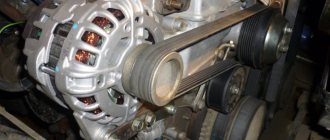
Where is the ignition system switch located? Its location is very simple, and all because it is located at the very top of the car engine, and it is very easy to get to. The switch is located near the vacuum booster, and it is attached to the car body with two nuts, so that you visually know its location, see the photo below:
When do you need to change the ignition system switch? If it fails, the engine may experience the following malfunctions:
- Firstly, the car’s engine may not operate steadily, both at idle and when driving the car.
- And secondly, very often there can be a loss of car throttle response; in other words, the car will drive worse.
Setting up SZ
If you have a VAZ 2109 carburetor, you will have to adjust the ignition system from time to time. This procedure is not the simplest; it requires following clear instructions. The operating procedure is as follows:
- We take the manual for our “nine” in our hands, set the contact gaps in accordance with the recommended values. Typically this is 0.45 mm.
- The ignition timing is set using special equipment, we miss this point.
- We connect the high-voltage wires and begin adjusting the torque in the middle of the stroke.
- Install the spark plug in the first cylinder and turn on the ignition.
- Turn the pulley counterclockwise 45°.
- We connect the ground to the spark plug, turn the pulley gradually in a clockwise direction until a spark appears between the electrodes.
- We look at the marks of the cover and pulley. They must be on the same level.
- To ensure that the marks coincide, we turn the distributor in the desired direction.
- If the marks do not match, the ignition will either be late or turn on prematurely, which is unacceptable.
- We rotate the pulley and distributor until we get the desired result, after which the distributor will need to be tightened, and then turn the crankshaft two turns.
- Check the result: if everything works fine, we finish the adjustment.
- You need to warm up the engine, then drive at a speed of 40-50 km/h, switch to fourth gear and accelerate sharply. If there is a knock, the ignition worked prematurely, we adjust it again.
What is the switch on VAZ 2108 cars?
This element in the operation of a car is an electronic unit that, receiving signals from a special magnetic induction sensor (also known as a Hall sensor), controls the operation of the ignition system. The schematic diagram of the device will not particularly worry us, because if the switch breaks down, it is simply replaced with a new one; it is much more important to understand how it works and, most importantly, how to diagnose it if necessary. But first things first.
The VAZ 2108 switch is connected directly to the ignition key, through which it is powered from the vehicle electrical network. The operating diagram of the device also assumes a direct electrical connection with the ignition coil and the spark plug distributor. The task of the automobile switch is to regulate the operation of automobile spark plugs through the ignition distributor using control signals from the sensor.