The task of the VAZ 2107 ignition system is to generate a spark that ignites the air-fuel mixture in the cylinders. In older “classic” models, this works based on the “breaker-ignition coil” connection. On more modern cars, a contactless ignition system is installed, where the VAZ 2107 ignition switch is responsible for sparking.
Switch malfunctions affect the efficiency and performance of the entire ignition system and the vehicle as a whole. Therefore, it will not be superfluous to learn how to check the VAZ 2107 switch and replace it, if necessary.
Switch Purpose
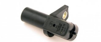
The switch is designed to interrupt the electric current flowing through the primary winding of the ignition coil, according to a signal from the Hall sensor. The interruption results in a high voltage current flowing to the spark plugs.
In addition, the switch automatically regulates the period of current accumulation in the ignition coil depending on the crankshaft speed. It also turns off the current supply through the ignition coil when the engine is not running but the ignition is on.
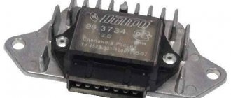
Microprocessor switch with automatic octane corrector “Astro” 962.3734
PURPOSE Microprocessor switch 962.3734 with automatic octane corrector (hereinafter referred to as MKAOC) provides sparking in contactless ignition systems of four-cylinder, four-stroke gasoline internal combustion engines. Installed on cars: VAZ-2105, -2106, -2107, -2108, -2109, -2110, -21213, -2130 and their modifications.
MKAOC allows you to: — automatically adjust the ignition timing depending on the quality of gasoline used, load and other factors, without driver intervention; — monitor the health of the Hall sensor and the switch control circuit; — set the initial ignition timing. Installed on carburetor cars equipped with an analog contactless ignition system.
DEVICE AND PRINCIPLE OF OPERATION MKAOC is built on a microcontroller using a broadband knock sensor. Processing signals coming from standard sensors and a knock sensor allows the system to automatically adjust the ignition timing depending on the quality of gasoline used, load and other factors, without driver intervention. Operates without a knock sensor like a regular switch.
ADVANTAGES OVER OTHER SWITCHES • Automatic adjustment of the ignition timing (IAF) • Diagnostics of faults • Allows you to set the initial ignition timing without special equipment • Reduced fuel consumption (with a working engine with an adjusted carburetor) • Increased engine life • Increased engine traction torque at low speeds • Improved acceleration dynamics • Easier engine starting (multi-spark mode) • Reduced engine noise (sharp reduction in detonation) • Quick shutdown of the ignition coil (0.5 sec.)
TECHNICAL CHARACTERISTICS • Supply voltage 8...16 V • Permissible crankshaft rotation speed 6000 rpm • SPD adjustment range 0...11° • SPD adjustment downwards when starting the engine 3° • SPD adjustment discreteness, per ignition stroke: - to the side decrease (during detonation) 1...2° - towards increase 0.1...0.2° • Switching current 7.5...8.5 A • Maximum current consumption 3 A • Ignition coil shutdown time 0.5 s. • Operating temperature range –40…+85 °C • Weight, no more than 200 g.
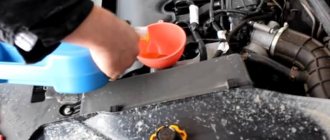
I installed it on a free technological hole with a ∅8 mm thread (thread pitch 1.25 mm) on the side of the oil dipstick near the 1st cylinder. Since my engine is well tuned, I didn't notice much of a difference, but I think it gets the job done.
I purchased this device for a long time, it is unknown for what purpose, now I have found where to put it.
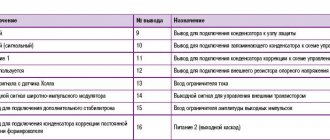
kit contents
DD mounting location
switch
Switch problems
- "The switch is on"
- Car engine does not start
- The engine “troits” - interruptions in sparking
Problems in the operation of the switch are one of the most common causes of operational failures of the power unit (of course, provided that everything is in order with the fuel system). Most often, switch malfunctions manifest themselves in the form of a drop in acceleration dynamics, failure to start the engine, “failures” during sudden acceleration, as well as “triple” of the engine. An experienced driver will immediately notice that something is wrong, and to be convinced of his theory, it will be enough to carry out simple diagnostics.
The most common cause of switch failure is a “bad ground,” which most often occurs after lengthy repair work or due to oxidation of the contacts. As a result of this, the device simply cannot send the appropriate impulses to the ignition coil, and without them the engine will not start and the car will not start.
For example, to check the condition of a contactless sensor, you need to measure the voltage at the output of the sensor-distributor.
In good condition, cranking the crankshaft with a key should cause a sharp change (often ranging from 0.2 - 0.4 V to 5 - 11 V). If this does not happen, the sensor most likely needs to be replaced. Diagnosing the status of the switch also does not take much time, and most often it does not require any special equipment.
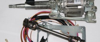
BZS adjustment
Adjusting the ignition of the VAZ 2107 begins with the simplest operation of removing the distributor cover, then turning the crankshaft until the maximum distance between it and the distributor is reached.
Installation process of BZS VAZ 2107
After this, they begin to unscrew the screws that fix the contact group on the bearing plate and between the contacts, insert a probe to determine and select the optimal position for the group
Contact angle correction in closed state
Ideally, everything is determined by the force applied to move the probe, which should be minimal; having found an area that meets this requirement, the position of the group is fixed by tightening the screws. The size of the gap also matters; to determine it, the thickness of the feeler gauge should be 0.44 millimeters. It is the adjustment of the gap that provides the required value of the angle of closed contacts; its optimal value is 55±3°.
Sources:
- https://ladaautos.ru/vaz-2109/kak-mozhno-proverit-kommutator-vaz-2109.html
- https://chinisam.ru/vaz/3204-kak-proverit-kommutator-vaz-2109.html
- https://zubilovaz.ru/vaz-2109-proverka-i-zamena-kommutatora
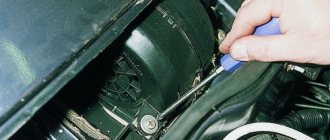
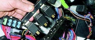
Where is the ignition system switch located?
Its location is very simple, and all because it is located at the very top of the car engine, and it is very easy to get to. The switch is located near the vacuum booster, and it is attached to the car body with two nuts, so that you visually know its location, see the photo below:
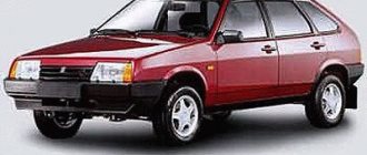
Modifications of VAZ-2109
VAZ-2109 . The basic model, which was produced from 1987 to 1997, was equipped with a 1.3-liter VAZ-2108 carburetor engine with a capacity of 64 horsepower.
VAZ-21091 . Modification of a car with a derated VAZ-21081 engine, 1.1 liter and 54 horsepower. It was mass-produced from 1987 to 1997.
VAZ-21093 . Modification of a car with a VAZ-21083 carburetor engine, 1.5 liters and 73.4 horsepower. Serially produced from 1988 to 2006.
VAZ-21093i . Modification with a VAZ-2111-80 injection engine, 1.5 liters. the first prototype appeared in 1994, mass production began in November 1998.
VAZ 21093-22 . Model made specifically for the Finnish market. It features improved interior trim, pre-installed alloy wheels and a new dashboard. The car was equipped with a 1.5 liter injection engine. Produced from 1995 to 1998.
VAZ-210934 . An all-wheel drive SUV with a VAZ-21093 body mounted on a Niva frame, on which the suspension, steering, engine, gearbox and transfer case from the same VAZ-2121 Niva model were already installed.
VAZ 2109-90 . A variant of the car, which was equipped with a compact two-section Wankel rotary piston engine with a volume of 654 cm3.
VAZ-21096 . Export modification of the VAZ-2109 for countries with left-hand traffic, the steering column was located on the right.
VAZ 21097 . Export modification of VAZ 21091 with right-hand drive.
VAZ 21098 . Another export modification, but this time the VAZ 21093 model with a right-hand steering column.
VAZ-2109 Carlota . A car produced from 1991 to 1996 in Belgium by Scaldia-Volga.
VAZ-21099 . The next independent car model, which is a modification of the “nine”. This car had a 4-door, 5-seater sedan body and a rear overhang extended by 200 mm.
How to replace the ignition system switch on a VAZ 2108-VAZ 21099?
Removal: 1) First remove the negative terminal from the battery.
2) Then disconnect the wire block from the switch by hand.
3) Next, use a wrench to unscrew the two side nuts that secure the switch to the car body.
Note! There will be a ground terminal under the left nut, so when the nut is unscrewed, disconnect this terminal from the switch!
4) And at the end of the operation, when the block is disconnected and the two side nuts are unscrewed, remove the switch from the car.
Installation: 1) First, install the new switch in its place, and then tighten the side nuts that secure it.
Note! Before you start screwing the left nut, install the ground terminal in the place where it will be screwed first, and only after that screw the left fastening nut!
2) Next, insert the wire block into the connector of the new switch.
3) And then, finally, install the “minus” terminal that you removed earlier on the battery.
Checking the ignition system switch for serviceability:
1) To do this, first disconnect terminal “K” from the ignition coil by unscrewing the nut that secures it with a wrench.
2) Next, using a test lamp, which is designed for “12 Volts”, with a power of “3 W”, check the coil for serviceability for this:
- First, connect the previously disconnected terminal to the control lamp.
- And then connect the other contact that comes from the control lamp in place of the “K” terminals on the ignition coil.
- And then, turning the engine over with the starter, check whether the lamp lights up or not.
Note! If it does not light up, then replace the ignition coil with a new one!
Important! On the very first ignition coils, instead of the “K” marking, the “+” marking was drawn, and therefore, if this is the case on your coil, then in this case, disconnect the wire next to which the “+” marking is located and not “K”!
The main thing
Whatever one may say, the VAZ is a car created without any modern and innovative technologies. Repairs of such a car in 80% of cases are carried out by the owner himself.
Repairing the ignition system of a given vehicle is no exception. The VAZ 2108 switch is the most vulnerable part in this system. Experienced craftsmen know that a switch from some models of Audi, Volkswagen and other car brands is suitable for the G8.
A spare part from a foreign manufacturer shows a higher service life without losses in impulse delivery and spark production.
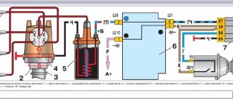
Wiring diagram for VAZ-2109 carburetor
- Headlight.
- Electric motor for headlight glass cleaning system. An optional part, used mainly on export vehicles.
- Limit switch for powering the engine compartment lamp.
- Klaxon.
- An electric motor drives a fan installed on the radiator of the cooling system.
- Temperature indicator that provides a control signal for the electric drive of the fan impeller.
- Alternator.
- Fluid supply valve for headlight glasses. Used in conjunction with paragraph 2.
- Fluid supply valve for the glass of the fifth door.
- Fluid supply valve to the front glass.
- Spark plugs.
- Hall sensor used to distribute ignition pulses.
- Coil.
- Limit switch for reverse gear lights.
- Fluid temperature meter in the cooling system.
- Starter.
- Accumulator battery.
- A sensor that measures the fluid level in the brake booster.
- Switch that controls the ignition system.
- Sensor for determining the position of the top dead center of the piston of the first cylinder. Installed on some export VAZ 2109 with a diagnostic system. Found only on cars before 1995.
- Diagnostic block. Optional element, installed together with item 20.
- Controller for controlling the solenoid valve installed in the carburetor.
- Starter switch contact block.
- Limit switch on the carburetor.
- Economizer valve.
- Sensor signaling an emergency decrease in oil pressure.
- Washer pump drive.
- Fan impeller motor for ventilation and heating systems.
- Resistance providing additional fan speeds.
- Speed shifter.
- Windshield wiper drive.
- Cigarette lighter.
- Illumination system for levers for adjusting heater operating parameters.
- Socket for additional equipment.
- Lamp for auxiliary lighting of the engine compartment.
- Illumination system for the glove box on the instrument panel.
- Relay and fuse link mounting block.
- Instrument panel light switch.
- Parking brake lamp limit switch.
- Brake lamp limit switch.
- Steering column switch lever block.
- Exterior lamp switch.
- Hazard switch.
- Turn on the rear fog lamp.
- Bimetallic fog lamp fuse.
- Heated glass switch on the fifth door.
- Turn signal repeaters on the front fenders.
- Central interior lighting.
- Individual lampshade.
- Switches for backlight operation on the middle pillars.
- Ignition switching unit.
- Egnition lock.
- “Low” type instrument cluster.
- Choke limit switch on the carburetor.
- Rear lights.
- Fuel level meter in the tank.
- Heated glass.
- Rear wiper drive.
- Two lamps for room illumination.
How is BSZ better than contact?
Having carefully read the previous section, you can see that the system uses an inductive non-contact Hall sensor. The advantage is obvious - there is no friction and commutation. For comparison, look at the contact system. In it, the breaker switches the voltage, the value of which is 12 Volts. Whatever one may say, the metal contacts are constantly in contact with each other, gradually wear out, and become covered with soot.
For these reasons, it is necessary to constantly monitor the breaker, adjust the gap, and carry out timely replacement. BSZ is devoid of these shortcomings, therefore, without third-party intervention, the system operates much longer. The Hall sensor fails very rarely, as does the switch. This increases the reliability of the system, but precautions must also be taken, in particular, the connection of the switch to the body must be as tight as possible to ensure effective heat exchange. In addition, BSZ allows you to improve engine performance, increase, albeit slightly, its power, along with increasing reliability.