When installing a head unit, car enthusiasts often encounter problems with wire pinout. It’s good if the car owner is well versed in such issues and can independently connect the radio, even with some nuances that arise during the installation process. If there is no such experience, then even a small trifle can drive you into a dead end. In this article we will look at what ACC means on a radio and the features of its connection when installing a car radio.
Connecting the radio
Correct connection of the head unit ensures its correct operation. There are several ways to supply power, both with and without an ACC cord. Some car enthusiasts, in addition to the control signal, supply power from the REM wire, which is used to power an amplifier or active antenna. 2 diodes are added to the circuit to ensure the correct direction of current. This option allows the receiver to function even when the ignition is turned off.
How to connect with ACC wire
The simplest and most widely used method is to connect power conductors to the cigarette lighter power circuit. However, it is not designed to connect additional consumers. Therefore, as the power increases, a voltage drop occurs, which negatively affects the operation of the power plant. When you turn off the ignition, the radio settings are reset. This is facilitated by the absence of a voltage supply circuit from the battery.
The correct, but more difficult to install option is to connect the red wire to the battery through the fuse block. The yellow signal cable is connected to the ACC terminal of the ignition switch. This connection method makes it possible to listen to the device only after power is supplied to the accessories. When the network is de-energized, the receiver turns off, and the discharge from the battery is reduced to several mA, which does not affect the condition of the battery.
Connection without ACC wire
If the head unit does not provide a control cord, then the connection option may be to connect the power (red) wire to the ACC terminal of the ignition switch. In this case, if the network is de-energized, the tape recorder settings will not be saved. Some vehicles do not have an ACC key position. Then the tape recorder is connected to the battery. To reduce the discharge of the latter, a control button is installed that breaks the power supply circuit of the GU.
This option is preferable to the previous one, since there is no voltage drop when the player’s power increases, and the battery is protected from excessive discharge. Any connection method must be carried out in compliance with safety rules. Poor twisting or poor contact may result in device failure or vehicle fire.
Do-it-yourself car radio installation and connection
Installing a car radio is a creative process, but not very complicated. An experienced car enthusiast, at least a little familiar with the basics of electrical engineering, will be able to connect the car radio with his own hands without any problems. We will tell you in this article how to properly connect a radio in a car, and in what order this should be done.
It should be remembered that an incorrectly installed and connected radio will not only sound bad, but may even lead to a short circuit or even a fire in the car.
A good video instruction for installing and connecting a car radio in a car can be seen in the video at the bottom of this page.
Incorrect connection of the car radio causes the following problems:
- When parked, the radio consumes too much electricity, as a result of which the battery is constantly discharged and if parked for a long time, there is a chance that the engine will not start.
- When listening to music at high volumes, the radio starts to “stutter” and significant distortion of the sound signal appears. Also, at high volumes, the car radio may simply turn off.
- When you turn off the power, the radio settings are lost.
All of these problems in 90% of cases arise due to incorrect connection.
Designations and decoding of radio wires
The rds function in the radio, what is it and how to enable it
Designations, decoding of contacts and wires of car radios.
Acoustic group:
R = Right speaker.L = Left speaker.FR+, FR- or RF+, RF- = Front right speaker (plus or minus, respectively).FL+, FL- or LF+, LF- = Front left speaker (plus or minus, respectively ).RR+, RR- = Rear speaker - right (plus or minus, respectively).LR+, LR- or RL+, RL- = Rear speaker - left (plus or minus, respectively).GND SP = Speaker common wire.
Power connector for radio:
B+ or BAT or K30 or Bup+ or B/Up or B-UP or MEM +12 = Battery powered (plus)
GND or GROUND or K31 or just a minus = Common wire (Ground), battery minus.
A+ or ACC or KL 15 or SK or S-kont or SAFE or SWA = +12 from the ignition switch.
N/C or n/c or N/A = No contact. (Physically the output is there but not connected anywhere).
ILL or LAMP or sun symbol or 15b or Lume or iLLUM or K1.58b = Panel illumination. +12 volts are supplied to the contact when the side lights are turned on. Some radios have two wires, -iLL+ and iLL-. The negative wire is galvanically isolated from ground.
Ant or ANT+ or AutoAnt or P.ANT = After turning on the radio, +12 volts are supplied from this contact to control the retractable antenna, if one is present, of course.
MUTE or Mut or mu or the image of a crossed out speaker or TEL or TEL MUTE = Input to turn off or mute the sound when receiving a phone call or other actions (for example, reversing).
Other possible contacts in radios:
Power Control = this is the control for turning on the amplifierP.CONT/ANT.CONT = this is the control of the antenna, power is supplied after turning on the radioILL + and ILL - = these are the wires for adjusting the brightness of the radio backlightAmp = Control contact for turning on the power of the external amplifierDATA IN = Data InputDATA OUT = Data OutputLine Out = Linear outputREM or REMOTE CONTROL = Control voltage (Amplifier)ACP+, ACP- = Bus lines (Ford)CAN-L = Bus line CANCAN-H = Bus line CANK-BUS = Bidirectional serial bus (K-line)SHIELD = Braid connection shielded wire.AUDIO COM or R COM, L COM = Common wire (ground) of the input or output of preamplifiersCD-IN L+, CD-IN L-, CD-IN R+, CD-IN R- = Balanced linear inputs of the audio signal from the changerSW +B = Switching power supply +B of the battery.SEC IN = Second inputDIMMER = Changing the brightness of the displayALARM = Connecting alarm contacts for the radio to perform car security functions (PIONEER radios)SDA, SCL, MRQ = Communication buses with the vehicle display.LINE OUT, LINE IN = Line output and input, respectively. D2B+, D2B- = Optical audio link
Marking and color coding of wires
Let's look at the color code for car radio wires:
- Black (indicated by GROUND or GND) is the negative of the battery;
- Red (ACC or A+ marking) is the plus of the ignition switch;
- Yellow (indicated by BAT or B+) is the positive from the battery;
- White with a stripe (marked FL-) is the minus of the front left speaker;
- White without a stripe (indicated by FL+) is a plus of the front left speaker;
- Gray with a stripe (marked FR-) is the minus of the right front speaker;
- Gray without a stripe (indicated by FR+) is a plus for the right front speaker;
- Green with a stripe (marked RL-) is the minus of the left rear speaker;
- Green without a stripe (designation RL+) is a plus for the left rear speaker;
- Purple with a stripe (marked RR-) is the minus of the right rear speaker;
- Purple without a stripe (designation RR+) is a plus for the right rear speaker.
The process of installing and connecting a car radio
The installation process for car radios of different types and manufacturers is not much different from each other. To do this, the container without a radio is installed in a standard socket and fixed by bending outward the metal petals along its perimeter.
- In modern cars, a special ISO standard connector is provided for connecting the car radio. The whole connection in this case comes down to the fact that you will need to insert the connecting block of the car radio into the corresponding ISO connector of your car.
- In older cars, as well as in many domestic cars, the ISO connector is not provided by design. To install a car radio in this case, you will have to purchase the appropriate connector and connect it yourself. Fortunately, the wires on such connectors are usually marked and signed.
Let's move on to connecting the car radio wires to the ISO connector. Take a look at the connection diagram below. As can be seen from the diagram, the left side of the ISO connector is responsible for powering and controlling the radio, and the right side is for connecting speakers to it.
Typical connection diagram for a car radio
The main step in connecting a car radio is connecting the power. It is at this stage that most mistakes are made.
Power is connected to the car radio through a separate fuse using a flexible stranded wire with a cross-section of at least 3 mm 2. In most cases, it will be enough to use a 10 ampere fuse; it will reliably protect the power circuit from emergency situations.
The radio is powered through three wires: yellow, red and black.
+12 V (yellow) – main power wire. It powers the built-in amplifier and also serves to save car radio settings. This wire is connected through a fuse directly to the battery. It is advisable that the length of the wire from the battery to the fuse does not exceed 30 cm.
ACC (red) – control of turning on the car radio from the ignition switch. On many vehicles, the ignition switches have an ACC (accessory) position. When you turn the key to the ACC position, power is supplied to the car radio, interior heater and cigarette lighter socket, but the car's ignition system is de-energized.
GND (black) – connects to the negative terminal of the battery. But this is ideal. Due to the low power of the car radio, it is allowed to connect the black wire to the car body. You must first ensure good contact with the body by cleaning the joint from dirt and oxides. You can also use contact lubricant to protect them from oxidation.
The yellow power wire can also be marked as B+ , BU , Batt .
It can be connected to the red ACC wire (bypassing the ignition switch) - this will allow you to listen to music without a key. But in this case, the radio will constantly consume current, and if the machine is idle for a long time (from several days to 2-3 weeks), your battery may run out.
The following wires are responsible for connecting acoustic speakers to the car radio:
- FL – front left,
- FR – front right,
- RL – rear left,
- RR – rear right.
When connecting the speakers to the radio, be sure to maintain the correct polarity, otherwise the sound will be of poor quality, since the acoustics in this case will work in antiphase.
In some car radios, the outputs to the speakers are duplicated with separate “tulip” type connectors - it is advisable to use them if the acoustics installed in the car have the same connectors.
It is advisable to use special speaker wires to connect speakers. They often come with a radio.
And do not even think about connecting any of the terminals intended for connecting acoustics to the ground of the car - you will be guaranteed that the car radio will fail!
The remaining wires in the car radio are responsible for controlling additional functions and equipment.
ANT (white) – antenna control. Acts as a power source for an internal active antenna, or provides a control signal to turn on an automatic external antenna.
ILL (ILLUMINATION) – is responsible for the backlight of the car radio. Connects to the “plus” of the side lights power supply circuit.
MUTE – controls muting the sound from the car mobile phone kit. The sound is turned off when this pin is connected to ground.
Parking Line – found on most car DVD players. Connects to the parking brake sensor. With this connection, you will be able to watch DVD only when the car is in the parking brake.
After connecting the power, acoustics and antenna wires to the ISO connector, this entire harness is pulled inside the container so that their ends with connectors extend into the car interior at a length convenient for work (approximately as shown in the photo at the beginning of the article), and connected to to the corresponding connectors on the rear wall of the radio.
After this, the car radio must be turned on and listened to. If everything works fine, then it can be inserted into the container until it stops (the latches on the sides should work).
Maintaining correct intake
How to connect a subwoofer to a standard Sony radio. connecting the subwoofer to the standard radio. installation nuances in cars of different brands
Only if the parent follows the basic rules for taking ACC powder will he be able to achieve a quick and trouble-free recovery for the child. Acetylsteine powder, according to the instructions, should be consumed according to the following scheme:
- At the age of 2 to 6 years - a whole package or half of it 4 times a day (maximum daily dosage - from 200 to 400 mg, which will depend on body weight).
- Children aged 6 to 14 years can take one sachet three times a day or two sachets - 2 times. The daily dose does not exceed 400 mg.
- Adolescents over 14 years of age are allowed to use two sachets three times a day (dosage no more than 600 mg).
The described treatment regimens for children of different ages have a good effect in the fight against any disease indicated in the instructions, excluding cystic fibrosis. To treat the disease, children aged 2 to 6 years are prescribed 1 packet four times a day; after 6 years, the number of packets increases to two, and the number of doses to 3. If the child weighs more than 30 kg, the daily dosage may increase slightly.
The treatment time with this remedy should not exceed a week. If the disease is chronic or during the prevention of exacerbation, the treatment period may increase, but the final decision will be made by the doctor.
Adaptive cruise control
Adaptive Cruise Control (ACC) is designed to automatically control vehicle speed. Adaptive cruise control is a further development of the cruise control system, which maintains a given constant speed.
Well-known adaptive cruise control systems are:
- Preview Distance Control from Mitsubishi;
- Radar Cruise Control from Toyota;
- Distronic ( Distronic Plus ) from Mercedes-Benz;
- Active Cruise Control from BMW;
- Adaptive Cruise Control from Volkswagen, Audi, Honda.
The adaptive cruise control system includes a distance sensor, a control unit and actuators.
The distance sensor is used to measure the speed and distance to the vehicle in front. Radars or lidars are used as distance sensors. Radar (Radio Detection and Ranging) emits electromagnetic waves at an object and receives a return signal - an echo. The speed of the car in front is estimated by the change in the frequency of the reflected wave, and the distance to the car is estimated by the time the signal returns. The set parameters are converted into electrical signals and transmitted to the control unit.
Lidar (Liht Detection and Ranging) uses an infrared laser beam. The operating principle of lidar is similar to radar. Laser sensors are cheaper than radars, but are susceptible to weather conditions, so premium cars primarily use radars for adaptive cruise control.
The distance sensor is installed on the front bumper or radiator grill of the car. The range of the sensor is about 150 m. The latest developments of adaptive cruise control use short- and long-range distance sensors. The short range sensor ensures that the vehicle slows down to a stop. Long range sensor – up to 30 km/h. This expands the functionality of the system and allows it to be used when the car is moving at low speed over a short distance (for example, when driving in traffic jams). For example, the Distronic Plus system uses three sensors - one long-range and two short-range.
What is ACC on a radio and how to connect it correctly
Registered: 09/26/2008 Messages: 21
Where to attach the ACC (red) power cable to the radio?
Subsequent topics with “stupid” names will simply be deleted. The title has been corrected. Quasar
AndriK on Okul
Registered: 08/02/2007Messages: 3377From: Taganrog 61 "OKULA" Vmax 168.3 km/h
To the “+” battery!
Registered: 02/15/2008Messages: 445From: Kazan. Car: Oka 111130 2006-Mlechka
Registered: 09/26/2008 Messages: 21
ALPINE Searched. Have not found.
AndriK on the Oculus It should receive +12 when the ignition is on.
Registered: 07/28/2006 Messages: 1183 From: Moskvangeles
ALPINE Searched. Have not found.
AndriK on the Oculus It should receive +12 when the ignition is on.
Registered: 09/26/2008 Messages: 21
Registered: 06/29/2007 Messages: 16380 From: Moscow-SVAO. Oka 0.75, Daihatsu Mira 0.66, Toyota LiteAce 2.2TD
Registered: 09/26/2008 Messages: 21
Registered: 08/14/2007Messages: 4697From: Svyardlovsk region
If you try a little and change the stock one (I highly recommend doing this, as it was discussed in the forum once) with a Volgov 3110, then. 3 additional outputs appear (just connect the wiring to additional equipment.
We attach the radio to it. Through the front (at 15-20A). If we want, we do it before working from the lock (not my option!), if we want, we do it permanently.
Registered: 11/26/2007Messages: 1646From: Murom, MB A140 Classic, ML320
voice
Article rating
Which cars have ACC installed?
Automakers care about maximum comfort for the driver and passengers. Therefore, most car brands have developed their own variations of the ACC system. For example, in Mercedes cars the adaptive cruise control system is called Distronic Plus, in Toyota cars it is called Radar Cruise Control. Volkswagen, Honda and Audi use the name Adaptive Cruise Control. However, regardless of the options for naming the mechanism, the principle of its operation remains the same in all cases.
Today, the ACC system can be found not only in premium-segment cars, but also in improved equipment in mid- and budget-priced cars, such as Ford Focus, Huyndai Solaris, Renault Duster, Mazda3, Opel Astra and others.
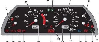
ACC operation indication on the BMW dashboard
Designations, decoding of contacts and wires of car radios.
Acoustic group:
R = Speaker right. L = Speaker left. FR+, FR- or RF+, RF- = Front speaker - right (plus or minus, respectively). FL+, FL- or LF+, LF- = Front speaker - left (plus or minus, respectively). RR+, RR- = Rear speaker - right (plus or minus, respectively). LR+, LR- or RL+, RL- = Rear speaker - left (plus or minus, respectively). GND SP = Speaker ground.
Power connector for radio:
B+ or BAT or K30 or Bup+ or B/Up or B-UP or MEM +12 = Battery powered (plus)
GND or GROUND or K31 or just a minus = Common wire (Ground), battery minus.
A+ or ACC or KL 15 or SK or S-kont or SAFE or SWA = +12 from the ignition switch.
N/C or n/c or N/A = No contact. (Physically the output is there but not connected anywhere).
ILL or LAMP or sun symbol or 15b or Lume or iLLUM or K1.58b = Panel illumination. +12 volts are supplied to the contact when the side lights are turned on. Some radios have two wires, -iLL+ and iLL-. The negative wire is galvanically isolated from ground.
Ant or ANT+ or AutoAnt or P.ANT = After turning on the radio, +12 volts are supplied from this contact to control the retractable antenna, if one is present, of course.
MUTE or Mut or mu or the image of a crossed out speaker or TEL or TEL MUTE = Input to turn off or mute the sound when receiving a phone call or other actions (for example, reversing).
Other possible contacts in radios:
Power Control = this is the control for turning on the amplifier P.CONT/ANT.CONT = this is the control for the antenna, power is supplied after turning on the radio ILL + and ILL - = these are the wires for adjusting the brightness of the radio backlight Amp = Control contact for turning on the power of the external amplifier DATA IN = Data input DATA OUT = Data output Line Out = Line output REM or REMOTE CONTROL = Control voltage (Amplifier) ACP+, ACP- = Bus lines (Ford) CAN-L = CAN bus line CAN-H = CAN bus line K-BUS = Bidirectional serial bus (K-line) SHIELD = Shielded wire braid connection. AUDIO COM or R COM, L COM = Common wire (ground) of the input or output of preamplifiers CD-IN L+, CD-IN L-, CD-IN R+, CD-IN R- = Balanced line inputs of the audio signal from the SW+ changer B = Power switch +B battery. SEC IN = Second input DIMMER = Changing the brightness of the display ALARM = Connecting alarm contacts for the radio to perform car security functions (PIONEER radios) SDA, SCL, MRQ = Communication buses with the car display. LINE OUT, LINE IN = Line output and input, respectively. D2B+, D2B- = Optical audio link
System elements
The modern ACC system includes three main components:
- Touch sensors that determine the distance to the car ahead, as well as its speed. The range of the sensors is from 40 to 200 meters, but it is possible to use devices with other ranges. The sensors are mounted on the front of the vehicle (for example, on the bumper or radiator grille) and can work according to the principle:
- radar emitting ultrasonic or electromagnetic waves;
- lidar based on infrared radiation.
- A control unit (processor) that reads information from sensors and other vehicle systems. The received data is checked against the parameters specified by the driver. The tasks of the processor include:
- determining the distance to the vehicle ahead;
- calculating its speed;
- analysis of the information received and comparison of indicators with the speed of your vehicle;
- comparison of driving speed with parameters set by the driver;
- calculation of further actions (acceleration or braking).
- Equipment that sends a signal to other vehicle systems - stability control system, automatic transmission, brake mechanisms, etc. All of them are connected to the control module.
Location of the sensor in the Distronic Plus system
Directions for use and doses
For adults and children over 14 years of age, prescribe 400-600 mg of acetylcysteine per day in 1-3 doses.
For children aged 6 to 14 years, prescribe 400-600 mg per day, divided into 2-3 doses.
For children aged 2 to 6 years, prescribe 200-400 mg per day, divided into 2 doses.
It is recommended to take the drug after meals. Dissolve the contents of the sachet with stirring in ½ glass of hot water and drink, if possible, hotter. Additional fluid intake enhances the mucolytic effect of the drug.
The duration of treatment for chronic diseases is determined by the doctor depending on the nature and course of the disease. For acute uncomplicated diseases, use acetylcysteine for 5-7 days.
System control principle
The activation and deactivation of adaptive cruise control is controlled by the driver and is carried out using a control panel, which is most often installed on the steering wheel.
- You can turn the system on and off using the On and Off buttons, respectively. If they are missing, the Set button is used as a replacement, allowing you to activate cruise control. The system is turned off when the brake or clutch pedal is pressed.
- You can set parameters using the Set button. After pressing, the system records the actual speed and continues to maintain it while driving. By using the “+” or “-” keys, the driver can increase or decrease the speed by a specified value with each press.
ACC operation control switch
Adaptive cruise control begins to operate at a speed of at least 30 km/h. Uninterrupted operation is possible when driving no more than 180 km/h. However, some premium-segment models are capable of operating from the moment they start moving and up to a speed of 200 km/h.
What does ACC mean on the radio?
Power to the car radio is supplied by two wires: power with a voltage of +12V yellow, black with a voltage of -12V. The ACC wire (also called signal wire) acts as a control wire and if it is not powered, the GU will not start. The ACC wire on the radio will be energized when the key is turned in the ignition switch.
The +B power wire has a constant voltage of +12V and allows you to store the necessary information in the car radio's memory (station frequencies, last played track, etc.) Unlike +V with a constant voltage, a signal is supplied to the ACC signal wire only when the head unit is running.
What is ACC
The car radio is powered by a yellow power cable connected to the battery and a black (-12 V) cable connected to the car body or the negative terminal of the battery. With this connection scheme, the GU will not be able to work, since there is no control signal. For this purpose, there is a red cord connected to the ignition switch.
When the key is turned to the ACC position, which means “accessory”, on-board consumers receive power, incl. control voltage is supplied to the GU. After this, you can control the device or it will turn on automatically if it was turned off by a power outage in the vehicle network.
Order in Moscow pharmacies
The information provided on drug prices does not constitute an offer to sell or purchase goods.
The information is intended solely for comparing prices in stationary pharmacies operating in accordance with Article 55 of the Federal Law “On the Circulation of Medicines” dated April 12, 2010 N 61-FZ.
| Drug name | Price for 1 unit. | Price per pack, rub. | Pharmacies |
| ACC granules for the preparation of a solution for oral administration 200 mg orange(s), 20 pcs. package (bag) made of combined material 3 g, cardboard pack 20 EAN code: 4030855000036 No. P N015474/01, 2009-11-16Hexal AG (Germany) | |||
| 5.3 | |||
| 5.3 | |||
| ACC granules for the preparation of a solution for oral administration 100 mg orange(s), 20 pcs. package (bag) of combined material 3 g, cardboard pack 20 EAN code: 4030855000029 No. P N015474/01, 2009-11-16Hexal AG (Germany) | |||
| 5.7 | |||
| 5.75 | |||
| ACC granules for the preparation of a solution for oral administration 200 mg, 20 pcs. package (sachet) made of combined material 3 g, cardboard pack 20 EAN code: 4030855511211 No. P N015474/01, 2009-11-16Sandoz dd (Slovenia) | |||
| 6 | |||
| 9.3 | |||
| ACC powder for the preparation of solution for oral administration 200 mg orange(s), 20 pcs. package (bag) of combined material 3 g, cardboard pack 20 No. P N015474/01, 2009-11-16Sandoz dd (Slovenia) | |||
| 6.3 | |||
| ACC granules for the preparation of a solution for oral administration 200 mg, 20 pcs. package (bag) made of combined material 3 g, cardboard pack 20 EAN code: 4030855000050 No. P N015474/01, 2009-11-16Hexal AG (Germany) | |||
| 6.5 | |||
| ACC granules for the preparation of a solution for oral administration 600 mg, 10 pcs. package (bag) of combined material 3 g, cardboard pack 10 No. P N015474/01, 2009-11-16Sandoz dd (Slovenia) | |||
| 13.4 | |||
| ACC powder for the preparation of solution for oral administration 600 mg, 6 pcs. package (bag) of combined material 3 g, cardboard pack 6 No. P N015474/01, 2009-11-16Sandoz dd (Slovenia) | |||
| 20.17 | |||
| ACC granules for the preparation of solution for oral administration 600 mg, 6 pcs. package (bag) made of combined material 3 g, cardboard pack 6 EAN code: 4030855000067 No. P N015474/01, 2009-11-16Hexal AG (Germany) | |||
| 20.17 | |||
| ACC granules for the preparation of solution for oral administration 600 mg, 6 pcs. package (bag) three-layer 3 g, cardboard pack 6 EAN code: 4030855511228 No. P N015474/01, 2009-11-16Sandoz dd (Slovenia) | |||
| 22.83 | |||
| ACC syrup 20 mg/ml, 1 pc. dark glass bottle 100 ml with a measuring cup (cup) and a dosing syringe, cardboard pack 1 EAN code: 4030855504855 No. LP-002668, 2014-10-21Sandoz dd (Slovenia) | |||
| 202.9 |
WARRANTY:
The manufacturer guarantees that the system meets the requirements of the specifications, subject to the conditions of operation, installation, storage, and transportation. The product must only be used in accordance with the operating and installation instructions. The product is subject to professional installation only at installation centers.
The consumer is deprived of the right to warranty service in the following cases:
upon expiration of the warranty period;
in case of violation of the rules of installation, operation, transportation and storage;
if there is damage due to incorrect settings or adjustments.
in case of mechanical damage to the external parts of the module, key fobs after the moment of sale, including exposure to fire, accident, ingress of aggressive liquids and water, careless handling;
This warranty does not apply to key fob batteries, which have a naturally limited service life.
Repair and maintenance of a module with an expired warranty period are carried out at the consumer's expense under separate agreements between the supplier/installer and the consumer.
Serial number ________________________
Keep this manual only outside the vehicle, out of reach of a potential thief.
“K8AB-PH Phase Rotation/Loss Monitoring Relay Ideal for monitoring phase rotation and phase loss in industrial circuits and equipment.• Simultaneously monitors phase rotation and phase loss in three-phase 3-wire power lines.• Single output changeover contact (SPDT) , 6 A at. »
“4.2 Linear displacement transducer PLP-05M1-11 Composition of the transducer PLP-05M1-11 YASHM.401263.031: – adjustable eddy current sensor YASHM. 400620.037 1 piece; – electronic microprocessor type unit. »
“State Autonomous Educational Institution of Higher Professional Education Moscow City University of Management of the Moscow Government Institute of Higher Professional Education Department. »
“CONTENTS 1. Introduction 2 General provisions. 1.1. 2 General view of the TYTAN EOS EPS and TYTAN EOS MW systems. 1.2. 3 Scope of application of the TYTAN EOS EPS and TYTAN EOS MW systems. 1.3. 3 Conditions of work. 1.4. 3 Basic tools and accessories. »
"1. Goals and objectives of mastering the discipline.1. Acquisition of modern knowledge about the nature and origin of the Earth's alternating electromagnetic field, the interaction of the Earth's magnetosphere with solar wind flows, solar-terrestrial connections, geomagnetic activity, atmospheric-ionospheric and a
“UDC 821.161.1–1 N. N. Kundaeva Title-final complex as a genre-marking element in an impressionistic text The article, based on the material of short prose of the first third of the 20th century, examines the features of the phenomenon of title-final complex, reflecting the process of transformation of canonical genres within the framework of impressions. »
"Controller MUT int. 1 MRT 01 MUT Meccanica TOVO www.mutinternational.com Weather-compensated controller for heating systems MRT Installation and service manual June 2005 Controller for controlling pumps and mixing valves in heating systems. The controller is used in all types of heaters. »
"ISSN 2409-9228. Bulletin of Dnipropetrovsk University. Series “World Dominion and International Economic Newsletters”, Issue 7, 2015 UDC 339.72 N. V. Stukalo, E. A. Solonskaya Sitnik* Dnepropetrovsk National University named after Oles Gonchar. »
“Yu.V. Sharipov Nizhny Tagil Denisov family Genealogy of the descendants of the bronze master Nizhny Tagil Photo on the first page: the Denisovs Pavel Vasilyevich, Mikhail Vasilyevich, unknown in military uniform, are standing: the Denisovs Leonid Frolovich, Lidia Frolovna and Agniya Frolovna. Nizhny Tagil, 1916 Sharipov Yu.V., 2001-2004 Topic. »
2017 www.lib.knigi-x.ru – “Free electronic library - electronic materials”
ACC mode ignition switch
Post by Ollegg » 02 Sep 2010 23:03
Post by gomel » 02 Sep 2010 23:10
Post by Slasher » 03 Sep 2010 00:00
Post by phoptik » 03 Sep 2010 09:29
Post by Ollegg » 03 Sep 2010 11:19
How did you figure out what it consumes and how much?
in any case, it will consume something, even with the socket removed, otherwise the settings will be reset if a couple of LEDs are lit in sleep mode, then that’s nonsense, it won’t consume much
In general, I did not expect such perversions from the branded electronics manufacturer Pioneer when I installed the P700BT a year and a half ago (it cost 8000-9000 rubles at that time) - neither with power nor with settings
As a result, it turns out that you can turn it on either automatically when you turn on the ignition, or manually with a button - there’s no way to connect both methods together. and when you disconnect the battery, you need to configure everything again.
phoptik it won’t work for PionEr to work, you need to put “+” in two points.
Post by Simss » 03 Sep 2010 12:09
What is adaptive cruise control
In the automotive industry, cruise control was introduced in the mid-20th century, when Chrysler introduced the world's first cruise control designed for vehicles in 1958. A few more years later - in 1965 - the operating principle of the system was revised by American Motors, which created a mechanism that is closest to the modern one.
How adaptive cruise control works
Adaptive Cruise Control (ACC) has become an improved version of classic cruise control. While a conventional system can only automatically maintain a given vehicle speed, adaptive cruise control is capable of making decisions based on traffic data. For example, the system can reduce the vehicle's speed if there is a hypothetical danger of colliding with the car ahead.
The creation of ACC is considered by many to be the first step towards full automation of vehicles, which in the future will be able to operate without driver intervention.
what does it mean and how to connect
When installing a head unit, car enthusiasts often encounter problems with wire pinout. It’s good if the car owner is well versed in such issues and can independently connect the radio, even with some nuances that arise during the installation process. If there is no such experience, then even a small trifle can drive you into a dead end. In this article we will look at what ACC means on a radio and the features of its connection when installing a car radio.
What does ACC mean on the radio?
Power to the car radio is supplied by two wires: power with a voltage of +12V yellow, black with a voltage of -12V. The ACC wire (also called signal wire) acts as a control wire and if it is not powered, the GU will not start. The ACC wire on the radio will be energized when the key is turned in the ignition switch.
The +B power wire has a constant voltage of +12V and allows you to store the necessary information in the car radio's memory (station frequencies, last played track, etc.) Unlike +V with a constant voltage, a signal is supplied to the ACC signal wire only when the head unit is running.
Why does a goat need an accordion in the kingdom of Nesmeyan?
Why do you need Wi-Fi in a car radio? Let's answer briefly - we need it. Today, almost any smartphone is capable of distributing the Internet via Wi-Fi. Although in this case it is more convenient to install a USB modem and establish a full connection with the navigator. A Wi-Fi module with an antenna turns the radio into a router with a convenient tariff plan.
The radio can be powered from a car battery for quite a long time. Longer than it takes to charge a smartphone. It makes sense to consider the device as a backup.
Who needs and in what cases is NFC used in a car radio ? NFC is a communication technology with a fundamentally short range. That is why this protocol is used in payment systems, for locks, tickets and access systems.
The advantage of the system is that the NFC antenna can be very miniature and does not require power. The active module is able to read tags and perform pre-defined actions. For example, when the system reads the chip of your smartphone, the radio can connect via a wireless interface automatically. Programming NFC tags for a radio is a rather tedious task due to the limited capabilities of the device’s processor. Purely technically, you can cut NFC chips from used travel cards and write an action script for each. But it’s much more convenient to set up voice control via a smartphone.
Answers
Wolfsangel 6 (17779) 2 3 14 8 years
B+ => battery positive, plus power, bold wire. Rem – Remote – throws either to ACC or to the radio – based on a signal from this wire, the amp turns on and off – you need to avoid consuming current when the mafon/engine is turned off and not to put it on It has a separate switch. GND – ground – body, also known as minus.
On the amplifier, rem. Typically refers to remote control. For car audio amplifier, the remote connection can be for the remote control. Typically this is a dial on one end and a telephone jack, for example, connecting to the other. This allows you to reduce the gain or volume on the amplifier wherever you want to mount the remote. If there is a terminal (screw and clamp for fastening wires) under the rem mark, then for remote shutdown. A remote shutdown for external amplifiers, such as subwoofers or high-level speakers, connects a thin blue wire from the head unit or radio to the amplifier. For head units or radios, the remote connection is connected to the ignition system. They both allow you to turn off the amplifier when the key or radio is in the off state. For home theater amplifiers, the remote connection can be for several things. This could be for an IR receiver or an infrared receiver, or for control from another device. These two are usually a 3.5mm female connector. If it looks like a 2-prong 110V outlet, it will cut off power to the other device when the amp turns off.
The radio is a built-in device designed to connect to the vehicle’s on-board system and additional devices for which it acts as a head unit. To enable such communications, standardized interfaces have been developed for these purposes, providing connections to specific pins on an electronic circuit. For each such output, not only a standard interface has been developed, but also a name that simplifies search and connection. This review gives the most common decoding of radio tape recorder designations using Pioneer as an example.
Connecting the radio
Dual ISO connector
The standard audio systems of some cars are connected with a double plug. The pinout of connectors for them is standard. The contact halves are connected to each other by a durable plastic jumper and secured with a special clamp. For correct installation, a guide groove is used, which prevents the plug from being installed in the wrong position.
The black one connects a current source to the radio, the brown one for acoustics.
GND on the motherboard circuit in the radio or camera: what is it
Many people are interested in what role GND plays on the motherboard or radio circuit diagram and what it even is. Literally, this is “earth” (from the English word “ground”). Some also use the term to mean "mass" or "minus". In fact, this is a common wire, which is usually white or black. The last option is more common. However, there are other power cord options. For example, blue, green, orange, red and yellow.
It is important to consider the following decodings when repairing the motherboard:
- GND (ground or ground). We are talking about the zero potential point of the microcircuit.
- VEE (Voltage Emitter Emitter) In this case, we mean the minus of the power supply in relation to GND.
- VCC (Voltage Collector Collector is a “voltage collector”). This is just a plus of power in relation to GND.
It is also important to consider that the abbreviation GND may have a slightly different form, for example, DGND, GNDD. This is how digital land will be designated
Analog ground, in turn, can be designated by the abbreviations AGND or GNDA.
To understand the essence, an elementary example should be given. It was necessary to connect an additional fan in the computer case to prevent the unit from overheating. Standard capacity was not enough. Zero fan, black wire was connected to the molex connector wire on the power supply. By the way, it is also made in black. In this case, this is “earth”.
The power supply to the fan itself was yellow. It was connected to a Molex power cable of the same color.
Important! In this case, you should understand simple “arithmetic”:
- When the yellow and black cords are connected, the output is a charge of 12 W.
- The combination of red and black gives only 5 volts.
This is important to consider in order to calculate the required voltage. Otherwise, a short circuit and subsequent malfunction may occur, which is sometimes impossible to eliminate.
By the way, you can also find “POWER” markings on the board and connectors. Here it means nutrition (with a plus sign).
Be sure to pay attention to the sockets with connectors. Sometimes, their design can eliminate incorrect connections
By the way, the computer buttons themselves, for example, reboot and turn on, do not matter at all how you connect them, because the main thing here is the circuit. Pros and cons do not play any role here
Adapters for ISO connectors
Cutting off a non-standard standard plug and connecting the wires directly is not recommended, because over time the connection will become loose, may oxidize, you will have to solder not only the wiring, additional repairs will be required, replacing blown fuses. Sometimes there are acoustics with three outputs, but they have standardized markings and electrical circuits that allow you to connect standard cables to the device using pinouts. You can buy any type of adapter for ISO connectors from one model to another.
The car may not be equipped with connectors, then you need to connect the radio connector to the cable directly. This is done by twisting, soldering, or using a terminal block that does not require subsequent insulation. When twisting and soldering, heat shrink tubing is used for safe use of the equipment.
How to properly connect to an electronic device
The concept of an interface as we know it today dates back to the 1960s. More precisely, in 1964, when the company developed its legendary IBM System/360 mainframe. It was then that the main tasks of any interface - physical or virtual - were formulated. They were to provide a standard connection for all devices.
Euro connectors
Initially, only a few types of standard inputs could be made to ensure compatibility between products from different manufacturers. This was a PS/2 port for the keyboard, an LPT port for the printer, and a connector for the PCI card. Nowadays, each type of connection has its own standard interface; this approach greatly simplifies the development and sale of any type of device and allows you to understand their built-in capabilities. Here are descriptions of the main communication elements, first of all, the designation of the button on the radio, which are used on the panels of Pioneer and other car radios.
Description of the buttons on the front panel of the radio for control (decoding)
| Button labels | Button function |
| A.F. | Different RDS frequency, automatic search when reception is poor |
| ALL OFF | Everything is off |
| AMS | Music sensor, works on the principle of playing a number of tracks equal to the number of clicks |
| ANG | Panel adjustment |
| ATA | The radio turns on automatically when you turn off and rewind media tracks |
| A.T.T. | Quickly reduces volume |
| BAND | Selecting a radio receiver |
| BEER | Enabling sound when pressing buttons |
| Blank Skip | Skips pauses longer than 8 seconds |
| BMS | Compensates for low frequencies when dropped due to the main device |
| BTM | Remembers the quality frequency of strong stations |
| CLK ADJ | Adjusts time |
| COLOR | Color |
| DISP | Display activation |
| DNPP | Selecting a CD in the changer |
| DNPS | Entering disc names |
| DSP | Activating the sound processor |
| EJECT | Remove the cassette from the cassette receiver or disc |
| EON | Reception of traffic information |
| FUNCTION | Switches the most used functions |
| INTO SCAN | Plays the recording for 10 seconds to search |
| LOS | Looks for stations, skipping with weak reception |
| LOUD | Tone compensation |
| M.RDM | Disc random playback |
| P.I. | Automatic search |
| PI SOUND | Switching to another frequency |
| PI MUTE | Muffled sound |
| POWER | Shutdown |
| PS | Listening to saved settings |
| PTY | Selecting a genre |
| RDS | Search for a station by metadata |
| RDM | Play disc tracks in any order |
| REG | Switching to the frequency of a radio station with RDS |
| Repeat Play | Replaying a track |
| SCAN | Scanning tracks and playing the beginning |
| SEL | Settings |
| SHUFFLE PLAY | Play available music in random order |
| SYSTEM Q | Tracking sound enhancement factors and showing them on the display |
| TA SEEK | Searching for a station with RDS |
| TC | Calling the tuner when rewinding |
How does the adaptive cruise control (ACC) system work?
All new trucks are equipped with a cruise control system. Cruise control ensures that the vehicle maintains a constant speed under various road conditions, which can significantly reduce the load on the driver when driving on the highway.
However, when driving in heavy traffic, the driver must independently adjust the speed of the vehicle depending on the speed of the traffic flow. The benefits of using the cruise control system decrease as traffic density increases.
How does the adaptive cruise control (ACC) system work?
Adaptive Cruise Control allows you to bypass the limitations of the conventional cruise control system. If it is necessary to reduce speed due to a vehicle ahead, ACC reduces the engine throttle opening and (if necessary) applies the brakes to maintain a safe distance between the vehicles as set by the driver.
Even in heavy traffic, when other cars are overtaking or occupying the lane in front of the car at different speeds, the driver does not have to constantly change the speed manually.
A radar sensor installed behind the radiator grille helps to detect objects in front of the car, estimate their relative speed and distance to them. Three radars, together with an integrated angular acceleration sensor, help determine whether the vehicle in front is moving in the same or adjacent lane. The driver sets the required average speed and distance to the vehicle in front.
To maintain the set distance, vehicle speed is maintained by active intervention of adaptive cruise control with the vehicle's systems.
You're probably wondering what the benefits of adaptive cruise control (ACC) are?
Firstly, the adaptive cruise control system reduces the load on the driver when driving. By monitoring the distance to the vehicle in front of you, ACC makes driving easier and reduces driver fatigue. Adaptive Cruise Control includes a Forward Collision Warning (FCW) feature that alerts the driver to take action.
Secondly, the Advanced Emergency Braking System (AEBS) further reduces the risk of collision with the vehicle in front by applying full braking when necessary.
When does the ACC system operate?
The ACC system will operate if:
- an object moving ahead is approaching, for example, if the vehicle in front has slowed down.
- an object previously identified as moving has stopped, such as a slow-moving stream of cars that has stopped moving.
The ACC system will not work if:
- an object moving ahead moves away, for example, a car overtaking you.
- an object previously defined as stationary has begun to move, for example, a stream of cars during a traffic jam.
- transport is moving in the oncoming lane.
What happens when the ACC system is activated?
The specified distance is set. If a vehicle is detected moving in front of you at a slower speed than you, ACC will ensure that a safe distance is maintained by reducing the speed. When the lane in which you are moving is free, the system will increase the vehicle speed to the set speed.
ACC alerts the driver if manual intervention is necessary to avoid a collision. Active intervention of FCW and AEBS in the operation of vehicle systems will follow if the driver does not respond properly.
Distance warning
- Audible distance warning and yellow warning signal on the central display of the instrument panel
FCW distance warning
- Audible distance warning and red warning signal on the central display of the instrument panel
Partial braking phase FCW
AEBS full emergency braking phase
The driver can enable or disable ACC and AEBS. FCW remains active even if the adaptive cruise control system is turned off.
Release form and composition
The following types of the drug are produced:
- Effervescent tablets ACC 100, ACC 200 and ACC Long, containing 100 mg, 200 mg and 600 mg of acetylcysteine, respectively;
- Solution for intramuscular and intravenous administration ACC Inject, 1 ml of which contains 300 mg of acetylcysteine;
- Granules for the preparation of a solution for oral administration ACC, one package contains 100 or 200 mg of acetylcysteine - granules with the smell of orange, 200 or 600 mg of the active substance - granules with the smell of lemon and honey;
- Orange granules for the preparation of syrup for oral administration of ACC. 5 ml of finished syrup contains 100 mg of acetylcysteine.
Advantages and disadvantages
Using an adaptive cruise control system has not only obvious advantages, but also some disadvantages. The benefits of ACC include:
- increasing the level of safety for the driver and passengers (the system helps to avoid accidents and collisions with the car in front);
- reducing the load for the driver (a motorist who is tired during a long trip will be able to entrust speed control to the automatic system);
- fuel economy (automatic speed control does not require unnecessary presses on the brake pedal).
Disadvantages of adaptive cruise control include:
- psychological factor (the operation of the automatic system can relax the driver, as a result of which objective control over the road situation will decrease);
- the possibility of technical malfunctions (no mechanism can be completely protected from malfunctions, so you should not completely trust the automation).
It is important for the motorist to note that in rain or snow conditions, the sensors on some devices may malfunction. Therefore, the driver must monitor the road situation in order to respond in time to a possible emergency situation.
Adaptive cruise control will be an excellent assistant on a long journey and will allow the driver to relax a little, entrusting the control of speed to the car. However, it is necessary to understand that it is unacceptable to completely lose control of the road situation: even the most reliable equipment can fail, so it is important for the driver to be ready to take full control of the vehicle into his own hands at any time.
REMOVE THE STEERING STEERING LOCKING MECHANISM IN PARKING POSITION.
1. Select a location to install the controller monoblock. Consider the length of the wires. Secure the module.
2. Install the USB connector in a convenient location.
3. If the car is equipped with a standard immobilizer, and you do not plan to bring the key every time you turn on the ignition, then install a standard immobilizer bypass (not included in the kit).
4. Connect pin No. 11 to the brake pedal end switch. When you press the pedal, +12V should appear on this wire. It is allowed to use the clutch pedal limit switch.
5. Connect pin No. 14 to the alternator warning lamp wire or to the oil pressure warning lamp wire.
6. Select a location for installing the “Engine Start” button, make a hole and install the button.
7. Disconnect the wires from the car's standard ignition switch. Connect them according to the connection diagram.
8. If the module is planned to operate under alarm control, connect contact No. 13 to the alarm output, to which ground is supplied in the “disarmed” state; if there is no alarm, connect this contact to ground.
The question often arises, what to do if the car has a chip key?
There are two main ways to solve this problem.
Method 1. When installing the module, leave the standard lock and insert the chip key into it before starting the engine.
The procedure is familiar to owners of many cars with a standard engine start button. There you also need to insert an electronic key to identify the owner.
Method 2. Install a bypass module for the standard immobilizer.
This is a device that, at the moment the engine starts, disables the standard anti-theft system by an external command, in this case by a command from the module.
The rest of the time the car is protected by the standard system. It is installed in exactly the same way as when installing an alarm system with auto start.
When you start the car using the button, the car should see the original chip. For this:
1. The key can be brought to the ignition switch, and after a couple of seconds it can be removed.
2. during the trip, before turning on the ignition, insert the key into the ignition and pick up the key when leaving the car.
3. remove the chip (or make a duplicate of the chip for starting) from the key and attach it permanently next to the antenna of the standard immobilizer.
4. install the standard immobilizer crawler (as when installing autostart).
Contact number PURPOSE
Attention! The module outputs are low-current and require the connection of additional relays!
The kit includes:
Operation and installation manual……. ………………………………………………………. 1 PC.
In the module's power supply circuit, it is necessary to install a 5A max fuse in the positive wire. The module provides overvoltage protection and circuit reverse polarity protection.
The system complies with the technical specifications of TU 4372-007-55684712-2006 and is recognized as suitable for operation.