As you know, motor oil, which is the working fluid of the oil system of a power unit, plays an important role in the overall design of the internal combustion engine. The main task of the lubrication system and the lubricating fluid itself is to prevent dry friction of the surfaces of mating parts, remove wear products and contaminants, and cool the surfaces.
Oil is supplied to some parts and components of the power unit under pressure, others are lubricated by splashing, and some elements receive lubrication due to the fact that the lubricating fluid simply flows onto them naturally.
The most widely used lubrication system is a “wet” sump lubrication system, in which the oil is constantly located in the oil pan. While the engine is running, the oil pump takes lubricant from the sump, which is actually a reservoir, after which the lubricant is supplied under pressure into the engine oil channels.
Note that although the solution is reliable and has long been proven, such a system is not without drawbacks, and under certain conditions it does not cope with its main task of protecting loaded parts. If the vehicle is to be used in such conditions, an alternative design, better known as a dry sump system, is often used. Let's look at the features of a dry sump oil system in more detail.
Engine dry sump system: purpose and design
So, as mentioned above, a dry sump is a type of lubrication system for an internal combustion engine. Let us immediately note that this system is actively used in sports cars, some SUVs and certain groups of special equipment.
The fact is that during sharp turns at high speed, with intense braking and acceleration, on ascents and descents, the car rolls and sways longitudinally and transversely. In this case, the oil in the sump of a conventional wet-sump lubrication system splashes heavily inside the sump.
This leads to foaming of the lubricant; the oil receiver may not “capture” the oil splashing in the sump, which inevitably results in oil starvation of the engine. In this case, the oil pressure drops sharply, and the engine itself experiences significant wear. It is not difficult to guess that not only the life of the internal combustion engine is greatly reduced, but there is also a risk of it overheating, jamming, etc.
A dry sump system is different in that the oil is not located in the sump, but in a separate oil tank. This approach eliminates the possibility of foaming of the lubricant. The friction pairs inside the engine are supplied with lubricant from the tank by a pressure pump, while the oil flowing into the sump is immediately pumped back into the oil tank using a pump-out pump. It turns out that there is no accumulation of oil in the pan, that is, the crankcase is dry.
Dry sump system design
Among the main elements it is worth highlighting:
- oil tank;
- injection pump;
- bilge pump;
- oil radiator;
- oil temperature sensor;
- oil pressure sensor;
- oil thermostat;
- oil filter;
- pressure reducing and bypass valves;
The oil reservoir (tank) can have different shapes (round, rectangular). There are special partitions inside the tank. They perform the task of oil stabilizers to minimize its vibrations during pumping and eliminate the possibility of foaming.
The tank is also ventilated. The main function, like that of the crankcase ventilation system, is to effectively remove excess air and gases from the oil tank, which enter there along with the engine oil from the sump.
Temperature and oil pressure sensors are also integrated into the tank, and there is an oil dipstick for checking the level. The oil reservoir itself is quite compact; the advantage is that it can be installed in the most suitable place in the engine compartment.
First of all, this allows for the best possible weight distribution, which is very important for sports cars in terms of handling. Another possibility of choosing the installation location allows you to place this element of the system in such a way as to improve the cooling of the tank and lower the oil temperature.
- The pressure pump is responsible for supplying oil to the lubrication system under pressure, while lubricant is pumped through the oil filter.
The pump is often located below the oil tank, which allows for constant pressure at the inlet, taking into account the force of gravity. Reducing and bypass valves are responsible for regulating the pressure in the system.
- The pump is used to ensure that the oil that flows into the sump is immediately pumped out and returned to the oil tank. The performance of such a pump is much higher than that of a pressure pump. Structurally, such a pump has several sections depending on the type and characteristics of the engine.
If the engine is highly boosted, there is one pump section in each section of the boat. On V-shaped engines there is also an additional section to separately pump out the oil that goes to the gas distribution mechanism. A similar section is installed on turbocharged internal combustion engines to pump out the oil that lubricates the turbocharger.
Both the pressure and bilge oil pumps are gear-type solutions. The pumps are located in a single housing and also have a common drive from the crankshaft. Less common are variants driven by a camshaft. The drive can be either chain or belt.
This design makes it possible to place the required number of sections on one shaft. The pumps are located externally on the engine and are easy to remove for repair or replacement. You can also find a design where the pumping and pumping pumps are implemented separately. This approach avoids an increase in the temperature of the oil in the tank as a result of the arrival of already heated lubricant from the sump.
Let us add that another feature of the bilge pump is that it is characterized by reduced sensitivity to the presence of air in the oil, foaming of the lubricant, etc. In other words, these pumps can absorb oil foam normally without loss of performance, which is not the case with conventional oil pumps in wet sump systems.
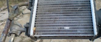
- The oil cooler is a liquid cooling radiator. This element is located between the injection pump and the motor. Another option would be to locate it between the sump pump and the oil reservoir.
Forced engines may additionally have another oil cooler, which is an air-cooled oil cooler. This radiator is connected to the system via an oil thermostat.
In a nutshell, if the engine is cold, the thermostat is closed at this time, which prevents insufficiently heated oil from entering the radiator. In other words, it is first important that the lubricant warms up and liquefies as quickly as possible in a cold internal combustion engine. In the future, the thermostat opens only after the engine oil has heated to the set temperature.
Purpose
So, a dry sump is one of the types of lubrication system of an internal combustion engine. Its popularity among sports and racing cars is explained very simply. When passing dangerous turns, intensive braking and acceleration, as well as on rapid descents and ascents, the car tilts, swaying longitudinally and transversely. At this time, the oil in the sump of a conventional wet sump splashes heavily throughout the entire system.
As a result, the fluid foams, the oil pump cannot take in the sloshing oil, which is why the engine does not receive the lubrication it needs. In this case, the pressure suddenly decreases, and the motor itself is subject to significant wear. It’s easy to guess that as a result, not only the engine’s service life is significantly reduced, but there is also a risk of it jamming, breaking and overheating.
But the operating principle of a dry sump implies a different device - the oil is not located inside it, but in a special tank. Thanks to this solution, the possibility of foaming of the liquid is eliminated. A pressure pump supplies lubricant to the parts rubbing inside the engine. Moreover, the liquid flowing into the pan is immediately pumped back into the tank using the appropriate pump. Thanks to this, oil does not accumulate in the pan, that is, it remains dry. This is how this system got its name.
What is a dry sump system and how is it different from a wet sump system?
A dry sump is a type of lubrication system for an internal combustion engine. It is installed on sports cars and many models of special equipment. Fundamentally different from traditional wet.
In models with a wet system, the oil is located in the oil pan, from where a powerful pump supplies it to the main line and through the channels. Under pressure, the oil is distributed throughout the engine, lubricates all parts and returns by gravity back to the crankcase.
This principle of lubrication is not suitable for some vehicles. In difficult driving conditions, the engine experiences “oil starvation”. For example, if the vehicle drives over very rough terrain or accelerates and brakes sharply, the oil overflows into the sump. The oil receiver is exposed and lubricant does not flow into the pump. The engine overheats from a lack of oil and in difficult cases can even seize and fail.
The dry sump lubrication system is fundamentally different from the traditional one. The oil in it is stored in a special tank and supplied to the parts by a pressure pump. The lubricant flowing into the pan is pumped into the oil reservoir by a suction pump without stopping.
Dry sump engines: advantages, disadvantages and where to put them
Conventional engines have a special pan at the bottom where all the engine oil is located.
From this pan, the pump pumps oil to lubricate the parts rubbing against each other through all channels. But now there are engines that do not have an oil pan. Let's figure out why this is done and where are these engines used?
Need for lubrication. Lubrication of all parts is very important for any engine. It happens that the oil channels become clogged and the engine oil is not pumped from the sump. This leads to parts overheating and sometimes even jamming.
Dry sump. Cars with a dry sump installed do not have an oil pan at the bottom, because it was specially moved outside the engine. What it looks like: a plate is attached to the bottom of the motor, from which a special hose comes out. He, in turn, pumps oil into the oil tank, which can be located either in the passenger compartment or in the trunk. The oil then passes through the cooling radiator and filter directly into the engine. The oil, in turn, is pumped thanks to two pumps.
Advantages. The main advantage of the dry sump system is to ensure an uninterrupted supply of oil with constant pressure under all vehicle driving conditions. In addition, the oil is cooled better, because it is stored in a reservoir remote from the engine. Smaller sump dimensions reduce engine height. This makes it possible to position the engine lower, thereby lowering the center of gravity (improving stability), and increasing aerodynamics (the bottom is flatter). When the crankshaft rotates, it does not experience the resistance of oil splashing in the sump and several horsepower is gained.
Well, the oil is not sprayed by the crankshaft throughout the crankcase (lubricant consumption is reduced) and foams less. The oil does not come into contact with crankcase gases and its service life increases. All of these advantages improve the overall reliability of the motor.
Flaws. The disadvantages of a dry sump engine include greater weight, design complexity and larger oil volume. And complexity means higher maintenance costs.
To convert road versions of some cars into racing ones, kits are available for sale. However, installing a dry sump system is only justified if the car will spend most of its time on serious off-road or on a race track. When driving on normal roads, all the benefits of a “dry sump” will not be noticeable, which means that such conversion will be a waste of time and money.
Where can you find such an engine? The most common option for installing such engines is on racing cars and special equipment. In the first case, a dry sump helps to avoid problems with outflow - the transformation of engine oil into foam during sharp turns.
Another well-known case is the ability to avoid the so-called “oil starvation”, because this design completely ensures the lubrication of all engine elements. Another advantage, which was briefly mentioned above, is the cooling of the oil as it passes through the radiator, and this completely reduces the temperature of the engine during heavy load.
Bottom line. Unfortunately, installing such a system on ordinary cars will be extremely problematic due to its large dimensions and very high cost. Moreover, in an urban “life mode”, the car will need an ordinary and familiar oil sump.
Dry sump benefits
The main advantage of a dry sump is stable oil pressure under any type of movement and position of the vehicle. Additional advantages of the system are:
- Additional oil cooling. This function is especially important for turbocharged engines.
- Pallet dimensions. The height of the sump when installing a dry sump system is lower. And this allows you to position the motor lower. This arrangement of the engine shifts the center of gravity and improves the aerodynamic characteristics of the vehicle. The car sways less while driving and its stability on the road is much higher.
- Increased engine power. Dry lubrication makes the engine easier to operate at the start. The crankshaft does not need to rotate at the start in an oil bath at a low lubricant temperature, therefore, it does not experience unnecessary resistance.
- Preservation of oil properties for a longer period. In a dry sump system, the oil does not come into contact with the exhaust gases, so it oxidizes slowly. Pollution practically does not penetrate into the oil tank.
A significant advantage of the system is easier maintenance of oil pumps. Oil pumps in dry sump designs are easier to replace or repair because they are located directly under the hood near the reservoir.
Advantages
As already mentioned, the operating principle of a dry sump makes it possible to achieve stable lubricant pressure under any circumstances and driving conditions of the machine. In addition, this system allows you to effectively cool the oil, which is extremely important for forced internal combustion engines, which are very sensitive to fluid temperature.
Regarding the specific configuration, the dry sump motor has a small sump, which significantly reduces the overall dimensions of the power unit. Thanks to this, such an engine can be mounted a little lower, moving the center of gravity and increasing the stability of the car. In addition, due to this, the aerodynamic properties also change positively, since the bottom of such cars is flatter.
By the way, this is why all modern motorcycles with forced engines are equipped with a dry sump. After all, it allows you to compactly place the lubrication system without compromising the technical characteristics of the device. So a dry sump for a motorcycle today is not a whim, but a necessity. At least for those that are designed for fast driving and have powerful forced internal combustion engines. It is this system that is presented in the most popular models: Honda Moto, Buell, EBR, KTM, BMW and other sports models.
The power of a dry sump motor is also slightly higher than that of its classic counterparts. Such engines start and spin up more easily, since the crankshaft does not have to rotate in oil and fight its resistance. In addition, it does not splash the liquid, due to which the oil density increases, it does not foam and, as a result, is consumed less.
Another advantage of a dry sump is the fact that it minimizes contact of the lubricant with the exhaust gases. Thanks to this, the oil oxidizes and ages more slowly. In addition, deposits and contaminants do not accumulate in the pan, due to which the lubrication system of the internal combustion engine remains cleaner for a long time.
The oil circuits are located outside the engine. This makes it possible, if necessary, to identify the cause of the breakdown much faster and repair the motor, without disassembling it. So we can say that dry sump lubrication systems are more reliable and easier to use.
So, a wet sump lubrication system. This solution comes up quite often. The principle of operation was explained above. Key elements of such a system:
Engineering is not for everyone
What is the main purpose of a dry sump system?
By and large, it was invented in order to ensure an uninterrupted supply of oil to the power unit even in the most extreme conditions. For ordinary city cars driving no faster than 80 km/h on a flat surface, such a system is not needed; a classic wet one is sufficient.
A dry sump can be useful on vehicles used in less than ordinary conditions. In addition to real SUVs and all kinds of all-terrain vehicles that overcome various obstacles, it is often found in sports and racing cars, which, although they do not jump over bumps, due to high overloads, oil also actively splashes around their engine.
Main oil line
Below the water jacket, along the right wall of the crankcase, there is the main oil line 11 (Fig. There are channels in the walls and bosses of the block to supply lubricant to the rubbing parts.
The upper section of the pump supplies oil through channels in the block to the main oil line, from where it passes to all rubbing surfaces. Unlike the ZIL-130 engine, the GAZ-53 engine oil from the lower section does not flow into the oil cooler, but into a centrifugal filter. Thus, the filter is connected in parallel and part of the oil passes through it, drained into the crankcase after cleaning.
| Diagram of a serial jet oil centrifuge KhTZ, connected to a branch of the main oil line and operating with a coarse filter. |
The RMC jet oil centrifuge of the D-54 tractor engine is connected to a branch of the main oil line.
The filter has a bypass valve that ensures oil flow into the main oil line, bypassing the filter, in case of significant contamination of the filter element, as well as in case of high oil viscosity during engine starting and warming up.
| Schematic diagram of the lubrication system. |
Oil pressure is controlled by electric pressure gauge 11, the sensor of which is installed in the main oil line, and the indicator is on the instrument panel. On some engines, to monitor the oil temperature, there is an electric thermometer 2, the sensor of which is mounted in the crankcase pan.
The connecting rod bearings and piston pin of compressor 6 receive lubricant from the main oil line 8 of the engine through a tube through the rear cover, seal and channels of the crankshaft and connecting rod of the compressor. After lubricating the compressor parts, the oil is drained into the engine crankcase through the chute of the compressor mounting bracket.
Oil pressure is controlled by electric pressure gauge 11, the sensor of which is installed in the main oil line, and the indicator is on the instrument panel. On some engines, to monitor the oil temperature, there is an electric thermometer 2, the sensor of which is mounted in the crankcase pan.
| Gear oil pump diagram. |
Oil pressure is controlled by electric pressure gauge 11, the sensor of which is installed in the main oil line, and the indicator is on the driver’s instrument panel. On some engines, an electric thermometer 2 is used to monitor the oil temperature, the sensor of which is located in the crankcase pan. Gear pumps are used in the lubrication system of automobile engines. The pump housing 5 (Fig. 12) contains the drive 7 and driven 2 gears. When the gears rotate, oil enters the suction cavity 6, fills the cavities between the teeth and is transferred in the cavities along the walls of the housing into the discharge cavity. Drive gear 7 is steel, mounted on a shaft, which is usually driven from the camshaft. Driven gear 2 rotates freely on the axle.
When centrally filling machines and mechanisms with lubricating oil, the valve pipe is connected to the main oil line.
The pressure in the lubrication system is limited by a pressure reducing valve located at the forward end of the main oil line. There is a hole in the valve through which oil is constantly supplied to the timing gears.
From channel 4 (Fig. 2.66, b), which connects the main oil line 2 with the main bearing, through hole 3, lubricant is supplied to the camshaft bushing 6. On the second journal, at the moment when the groove connects hole 3 with channel / (channel 6 in Fig. 2.66, a), oil flows to the channels in the head, and through them into the cavity of axis 4 (see Fig. 2.66, a) of the rocker arms and further - to the rocker arms and the upper tips of the rods.
The other, main part of the purified oil is sent through tube 13 to the main oil line.
What is the secret of the dry sump system?
Let's reveal another secret of cars. The average dry sump lubrication system consists of the following elements:
- pumping and injection pump;
- tank;
- filter;
- a set of highways and canals;
- radiator.
It must be said that automakers are being a little disingenuous when they call this lubrication system “dry sump.” In fact, in it, as in the classical scheme, the oil also flows into the sump, and the key difference is that it does not linger there and is sucked out by a pump that pumps the lubricant into a special tank, where it accumulates.
In fact, this tank is the main feature of the design - the lubricating fluid in it, thanks to its special design, does not splash or foam, which means it will always be available for work.
Then everything happens as with conventional engines. The feed pump pumps oil under pressure into the lines that transport it to critical engine components, and it reaches other elements by splashing or dripping.
A filter is necessary to clean the lubricant from various small debris, and a radiator is installed to cool it.
Sometimes there are designs with several radiators - one liquid and one air, which helps to better cool the hot oil that has been in the hottest corners of the machine’s power unit.
Possible problems with the system and how to resolve them
Some engine problems in the lubrication system may occur unexpectedly, even if you recently repaired the car or carried out its maintenance. Let's list the main problems and look at ways to solve them:
| Type of malfunction | Cause | Elimination |
| The oil pressure sensor does not light up when the ignition is turned on. | 1. The indicator is burnt out | 1. Replace the gauge bulb in the dashboard |
| 2. Damage to the wire, oxidation of the connector | 2. Inspect the connection and, if necessary, replace the wire | |
| 3. Failure of the oil pressure sensor | 3. Replace the sensor with a new one | |
| The oil pressure indicator lights up at idle and turns off when the speed increases. | Low oil pressure due to overheating. The cooling system is not working properly | “Drive” the car at high speeds for 15-20 minutes to cool the engine; Carry out a diagnostic inspection of the cooling system performance |
| The indicator on the dashboard lights up at increased engine speeds | Reducing valve faulty | Using a dipstick, check the engine oil level in the car and, if necessary, replace the pressure relief valve |
| The indicator is constantly on | 1. Too low amount of oil fluid | 1. Check the oil level and add if necessary |
| 2. The pump does not work, the oil pump channel is dirty | 2. Clean or replace the pump | |
| High oil consumption | Wear of cylinders, piston rings, valve stem seals, sealing elements | Inspect the engine system and eliminate the cause of the leak. |
And finally
The engine lubrication system protects the vehicle from daily overheating and significantly increases its service life.
Therefore, it is important to keep it in good condition. To do this, the driver must carry out timely maintenance of the vehicle and eliminate minor faults, which in the future can lead to expensive repairs.
For every “plus” there is a “minus”: do you need it?
Why not install a similar lubrication system on all cars? Indeed, the dry sump operating principle of which we are considering today has quite a few advantages.
In addition to the main advantage - uninterrupted oil supply under any conditions, there are several more. For example, in our case, large crankcases are not needed, so the engine can be made more compact.
Also, due to the fact that more lubricant circulates through the power unit, it is cooled better, which also has a good effect on its operation.
As always, there are several “BUTs” that have made dry sump the privilege of only select cars.
Firstly, the complexity of the design. Despite the fact that the engine itself can be made more compact, additional components appear around it (oil tank, radiators), due to which, in fact, the weight gain is not so noticeable. All this affects the cost and requires additional maintenance.
Secondly, such designs require more oil, and this is also an additional expense.
Disadvantages of the dry sump system
The system has not found widespread use, despite its large number of advantages. This is due to the following disadvantages:
- Complexity and high price. Due to the presence of a large number of elements that are not in a conventional engine lubrication system, the cost of the system increases, and at the same time the complexity of its maintenance. It is necessary, in addition to the usual parts, to install an oil tank, pumps, radiators and other elements;
- More oil by volume. Among the advantages, it was noted that the oil retains its properties longer, but it will require more filling;
- Increased weight. Additional parts and larger oil volumes increase the weight of the system.
In general, the “dry sump” system is a rather interesting development, but it is unlikely to be found in mass-produced cars in the near future due to the high cost of installation and maintenance of such a system.
( 112 votes, average: 4.43 out of 5)
Engine cylinder honing
Checking compression in engine cylinders: measurement method and analysis of results
Related Posts
What is the dry sump system used for?
The dry sump lubrication method is used mainly on sports cars and specialized vehicles that have to operate under unusual conditions. The essence of this lubrication method is that the oil is not in the crankcase. Accordingly, it does not need to be pumped out from there with an oil pump.
The fact is that when the car is moving along a city highway, it is not difficult for the oil pump to pump oil out of the crankcase and circulate it to work. Whereas, for example, when driving off-road, on a slope, from a slope and in other difficult situations, this is much more difficult to do. Due to the inability to pump oil out of the crankcase with an oil pump, since it flows over the crankcase from side to side, there is a high risk of oil starvation of the engine, and at the same time associated problems - overheating, jamming, cracks in the cylinder block, and so on.
Installation benefits
Pan Gasket
If we compare the operation of a dry sump with a conventional lubrication system, we obtain the following advantages:
significant reduction in the risk of oil starvation; lowering the vehicle's center of gravity. The oil reservoir allows the sump to be reduced in size so the engine can be lowered. Similar goals are pursued when installing a boxer engine; more efficient cooling of the lubricant. In the case of a wet sump, the main filling volume is constantly in contact with gases breaking into the crankcase, and the oil circulates only in heat-loaded lines
It is also important to increase the filling volume, which allows you to increase service intervals.
The dry sump system is most widely used in motorsports. In racing conditions, with repeated changes of direction, the oil in the pan is prone to loosening. And in long turns it collects on the side of the tray opposite to the direction of the turn. The installation of a dry sump on SUVs is due to driving on terrain. If the car is tilted strongly, the risk of oil slumping and starvation is also quite high.
What is a dry sump system?
The “dry sump” system does not have the problem discussed above with the difficulty of supplying oil from the crankcase to the system during uneven movement. A solution to the problem is achieved by using a separate reservoir (tank) where the oil is located. That is, oil is supplied to engine parts from the tank, and it is immediately pumped into the tank itself from the crankcase without remaining in it for a long time.
In general, a dry sump system consists of the following components:
- Oil storage tank;
- Pumps: injection and pump-out;
- Oil radiator;
- Sensors: oil temperature, oil pressure;
- Oil thermostat;
- Oil filter;
- Valves: pressure reducing and bypass.
The oil storage tank can be made in various forms. Inside the tank there are special partitions necessary to eliminate the possibility of oil foaming. There are also vents in the tank to allow excess air and gases that may enter the oil after going through the lubrication cycle to escape.
The oil storage tank itself is most often located in the engine compartment of the car. It has a dipstick that allows the driver to check the amount of oil in the tank. There are also temperature and pressure sensors inside the tank.
Please note: For sports cars, it is important to be able to place the oil tank almost anywhere on the car. This is necessary for better weight distribution.
The injection pump in this system is located below the oil tank, which allows a constant pressure based on gravity to be realized at its inlet. The pressure in the system is regulated using pressure reducing and bypass valves. The task of the injection pump is to pump oil from the tank through the oil filter into the lubrication system.
The scavenge pump performs the task of filling the tank with oil by constantly pumping it out of the crankcase.
Please note: Depending on the design of the engine, more than one bilge pump may be used, or several sections may be used in one pump. For example, on turbocharged engines this is necessary in order to also pump out the oil that lubricates the turbocharger, and in V-shaped engines, oil is additionally pumped out from the gas distribution mechanism.
Pumps in such a system operate via a chain or belt drive from the engine crankshaft.
It is worth noting that pumps in such a system are most often implemented in pairs in one housing. This makes it possible to reduce the cost of production and also arrange them more compactly.
Please note: The oil pumps used in a dry sump system are different in design from the oil pumps that can be seen in conventional designs. They are practically insensitive to the presence of air in the oil, that is, they are able to pump oil foam without loss of performance.
The oil cooler in dry sump systems can be located between the sump pump and the oil tank or between the charge pump and the engine. It is a liquid cooling radiator.
Oil cooling
To cool the oil, liquid-oil heat exchangers and air-oil radiators are used. In heat exchangers, the oil is cooled by the engine cooling system fluid, while in air-oil radiators it is cooled by air. The designs of heat exchangers can be very different. Shell and plate heat exchangers are usually used, installing them in the liquid path of the cooling system. Oil radiators are similar in design to radiators of the cooling system. The most widely used are tubular, tubular-plate and tubular-tape radiators. To increase heat transfer, swirl inserts are sometimes placed in the oil radiator tubes.
Heat exchangers have the following advantages compared to radiators:
- simplicity of design
- compactness and low weight, since the thermal conductivity of the liquid is much greater than the thermal conductivity of air
- simplicity of layout in the engine compartment
- no need for air circulation
- more stable oil temperature, independent of engine load and ambient temperature
- quick heating of the oil before starting in winter conditions using a liquid pre-heater
The disadvantage of heat exchangers in which the oil is cooled by the engine cooling system liquid is the fact that its temperature cannot be lower than the coolant temperature.
Oil tank
The reservoir used in a dry sump system can have different shapes. Inside the tank is equipped with special partitions that prevent vibrations and foaming of the oil when the car is rocking.
In addition, the tank is equipped with ventilation. It is necessary to eliminate gases and air from the tank that get inside along with the lubricant from the pan.
In addition, the tank contains thermostats, pressure sensors and a dipstick for checking the fluid level. The tank itself is compact, which allows it to be installed in any suitable location.
By choosing the optimal zone, you can also successfully distribute weight, which is extremely important for racing cars in terms of handling. Also, the operating principle of a dry sump allows the tank to be placed in such a way as to improve its cooling and reduce the temperature of the lubricant.
Pumps
The injection pump supplies oil to the system under pressure. In this case, the liquid passes through the oil filter. The pump is most often located just below the oil reservoir, which makes it possible to build the necessary pressure. By the way, bypass and pressure relief valves are responsible for its adjustment in a dry sump system.
The scavenge pump works by moving the oil trapped in the sump back into the oil reservoir. Its performance is much higher compared to a pressure pump. The design includes several sections, depending on the characteristics of the motor.
If the internal combustion engine is highly forced, there is one pump section in each crankcase fragment. V-shaped engines are also equipped with an additional section necessary for pumping out the oil supplied to the gas distribution element. The turbocharged engine is equipped with the same system to pump out the lubricant that processes the turbocharger.
Both the pumping and pumping pumps are of the gear type. They are located in the same housing and also have a common drive from the crankshaft. Systems with a camshaft are slightly less common. The drive can be either belt or chain.
Oil pump
During engine operation, oil circulation in the lubrication system is ensured by the main oil pump, driven by the crankshaft through the gear mechanism. To achieve a sufficiently high pressure in the lubrication system, high-pressure pumps must be used, among which gear, screw and plunger pumps can be distinguished. Typically, gear pumps with external (more often) or internal gears are used. They are easy to manufacture, reliable, have small dimensions and weight. Pump gears can be straight or helical.
Let's consider the operation of a single-section gear oil pump with a built-in pressure reducing valve. The oil coming from the engine sump or oil tank into the inlet cavity 1 of the pump enters the depressions between the teeth and, when the gears rotate, is transferred under pressure into the discharge cavity 2. The pressure in this cavity is limited by the pressure reducing valve 3, the spring of which is designed for a certain force.
Rice. Single-section gear oil pump with built-in pressure reducing valve: 1 - inlet cavity; 2 - discharge cavity; 3 - pressure reducing valve
Oil radiator
In an internal combustion engine with a dry sump, this spare part is represented by a liquid cooling radiator. The part is located between the motor and the injection pump. There are also other options when the radiator is located between the sump pump and the tank.
Forced internal combustion engines can be equipped with additional oil radiators, which are air-cooling elements. This radiator is connected to the system via a thermostat.
Flaws
As for the disadvantages, the dry sump system is considered more complex and expensive. The presence of many auxiliary parts leads to a natural increase in mass. In addition, more lubricant itself must be poured into such a system.
So internal combustion engines with such a lubrication system are several times more expensive, and the costs of their maintenance increase significantly, especially when it comes to repairing or replacing some elements. This is why a dry sump is not installed on most budget cars. After all, such machines, as a rule, are not intended for use in extreme conditions.
Oil filter
To purify oil (mainly from mechanical impurities), as a rule, two filters are used - coarse and fine. The first one is always full-threaded. It retains mechanical impurities, mainly wear products of engine parts. The fine filter is most often not full flow due to the high resistance it provides to oil flow. Some fine filters, in addition to retaining mechanical impurities, can also absorb water, free acids and alkalis due to special impregnations of the filter element. Coarse oil filters that are clogged during engine operation are washed or cleaned. Clogged fine filters are replaced with new ones at every oil change.
Coarse oil filters are similar to coarse fuel filters. They can be mesh, plate-, tape- and wire-slotted. On heavy diesel engines, two-stage belt-slot filters are most often used.
In fine filters, paper, cardboard, felt, sawdust, yarn and other specially impregnated materials are used as filter elements. The most widely used cardboard filter is the multi-beam star type. Previously, when only mineral motor oils were used, reactive oil centrifuges were often used as fine filters, in which mechanical impurities that contaminate the oil are separated under the action of centrifugal forces.
Centrifugal filters have significant advantages:
- they provide a high degree of oil purification with a relative simplicity of the process
- their filtering properties and throughput are almost independent of rotor contamination
- there is no need to replace elements during maintenance
At the same time, the practice of using centrifuges in lubrication systems that use synthetic and semi-synthetic oils has shown that, along with harmful impurities that contaminate the oil, some useful additives are also removed from it.
The Importance of Lubrication
For any engine, good lubrication of all parts is critical. To do this, very efficient pumps are installed in the engines, whose task is to ensure oil circulation in the unit. This pump is located in the engine sump or crankcase; through a filter element, it takes oil from below and delivers it upward through the oil channels. If some kind of failure occurs in this process, for example, due to clogged oil channels, then this ends in overheating of the rubbing parts and even their jamming.
What elements does the lubrication system consist of?
Each engine is equipped with a lubrication system consisting of the following components:
- Oil reservoir (oil tank). Located predominantly in the lower part of the engine;
- Oil intake - a pipe that supplies oil from the crankcase to the oil pump;
- Oil pump. There are gear and rotary ones. The latter are increasingly common in modern engines. The reason for this is the simplicity of the design and technological considerations. Rotary pumps do not allow the use of high-viscosity oils;
- Oil purification filter with corrugated paper element. In some cases, a coarse filter may also be used, but on most engines it is an oil intake mesh;
- Control system sensors (ECU).
- Oil supply channel system.
Varieties
Engine sump protection Is engine sump protection necessary?
All crankcases that cars are equipped with can be divided into two categories depending on which power unit they are installed on.
Therefore, it is customary to separately consider designs for:
- two-stroke internal combustion engines;
- four-stroke power plants.
The difference in crankcase design is due to differences in the design of the internal combustion engines themselves. Pallets are either detachable or non-detachable. Often the pan acts as an integral element of the crankcase, and does not simply serve to collect lubricating oil.
Two-stroke engines
The peculiarity of F. Carter's invention for a two-stroke engine is that the crankcase and the motor are one whole. This is an integral element of the housing and one of the components of the power supply system of the power unit.
It is inside the crankcase that the process of preparing the air-fuel mixture takes place. After this, the mixture moves into the cylinders of the power unit. This is one of the differences in comparison with the four-stroke analogue.
Also, two-stroke engines differ in that here the oil comes into direct contact with the fuel. When preparing a mixture for cylinders, the crankcase allows you to power the engine, and also simultaneously lubricate the elements of the cylinder-piston group.
Two-stroke diesel engine
This design of the system leads to the fact that fuel and lubricating oil are mixed inside the power unit. This explains the increased smokiness and darker color of the smoke produced and exiting through the exhaust pipe. The exhaust has a bluish tint, which is a characteristic feature of motor vehicles. It is there that two-stroke engines continue to be used, unlike cars.
On two-stroke engines, the service life of spark plugs is significantly lower compared to a four-stroke competitor. Two-stroke internal combustion engines are practically no longer found on cars, and motorcycle manufacturers are also abandoning them.
Crankcase and four-stroke engine
In the case of four-stroke engines, the crankcase plays a secondary or auxiliary role. Most often, the crankcase is needed only as a container for collecting oil, nothing more.
It is not difficult to explain this decision. Modern four-stroke engines do not welcome oil entering the cylinders. Therefore, their exhaust has less smoke and a lighter color. The exhaust composition is cleaner and more environmentally friendly.
An important component of a four-stroke engine in terms of exhaust gas purification is the catalyst. Now it is installed on almost all modern cars with internal combustion engines.
Location and purpose
Having understood what a car crankcase is, you can pay a little attention to the issues of its placement and functionality. Let's start with where exactly the power plant crankcases are located.
They are located in the same place as the engine itself, since they are its integral and integral part.
Let's start with where exactly the crankcases of the power plants are located. They are located in the same place as the engine itself, since they are its integral and integral part.
The crankcase acts as the space between the sump and the engine crankshaft. It is inside this space that the crank mechanism is located and carries out its movement. In fact, such an element as the engine sump is located in the engine. That is, the question of where it is is not entirely correct.
Since the crankcase has a container (pan) located to collect oil, very often both elements are described by the same concept. But in reality, the pallet is an integral part of the structure in question.
Mounting the engine to the frame
Despite the good balance of modern car engines, vibrations still occur during their operation, which should not be transmitted to the frame. Therefore, the engine mount (suspension) must be such as to reduce the transmission of vibrations to the car frame and prevent the appearance of stress in the cylinder block when the frame is distorted due to the car moving on an uneven road. Engines are attached to frames or semi-frames at three, four and five points.
The engine of the GAZ-24 Volga car is mounted at three points on rubber mounts. Two supports are located in the front of the cylinder block, on its sides, and one support is located at the rear, under the front of the transmission extension.
The ZIL-130 car engine is attached to the frame at three points: one support at the front and two at the rear (clutch housing feet). The engine of the GAZ-53A car is attached to the frame at four points: two supports in front and two in the back (flywheel housing and clutch feet). The KamAZ-5320 diesel engine is mounted at five points (Fig. 10): two front supports are installed on cylinder block 1 on its sides; two supports at the rear are reinforced on both sides of the flywheel housing 13; one support support is located on the gearbox housing 22.
The front supports consist of a bracket 4 connected to the cylinder block 1, and through a rubber cushion 7 and a coupler 6 - with a bracket 5. The latter is riveted to the rack 9, and the rack to the frame spar 10.
The rear supports consist of an engine bracket 12 mounted on the flywheel housing 13, and a rear support bracket 11 riveted to the frame spar 10. The bracket 11 with the cover 20 covers the shoe 16, installed between the brackets and connected by a bolt 15 to the bracket 12. The shoe is made of aluminum alloy and is located in a rubber cushion 14. Between the cover 20 and the bracket 11, adjusting shims 2L are placed. A steel sleeve 18, pressed into the shoe, prevents it from being crushed. .
The support support consists of a bracket 23 mounted on the gearbox housing 22. The bracket shelf is covered by a rectangular rubber cushion 27 located in the holder 25, connected through a lining 26 to a cross member 24. The latter is connected to brackets 28 riveted to the frame side members. Rubber cushions located under the supports reduce shock loads on the engine when driving
What is this
Engine lubrication system
You can often find situations where the crankcase refers to the engine pans, where all the lubricating oil for the engine, gearbox, etc. accumulates. But the crankcase is actually not synonymous with the pan.
It is correct to call the lower part of the cylinder block the crankcase, when speaking in relation to classic power plants, and not to refer to radial, recumbent, boxer and other not quite standard engines
The crankcase has a special cavity, which is designed to accommodate an important and necessary crank mechanism inside it, that is, the crankshaft
But the pan acts as a container for engine oil. It is directly related to the crankcase, since the pan is attached to it at the bottom.
The crankcase has a conditional division into upper and lower parts. Just in the lower compartment of the crankcase there is a fixed sump where motor lubricant accumulates during periods when the engine is not running.
It is fair to call the crankcase the main element of the power unit housing. The internal space is isolated, which allows you to create the most voluminous cavity in the motor. Inside the crankcase there is a crankshaft, and the upper part serves to house the cylinder block.
That is, in fact, the crankcase can be considered the body of the internal combustion engine, which includes an oil pan.
Location and purpose
Having understood what a car crankcase is, you can pay a little attention to the issues of its placement and functionality. Let's start with where exactly the power plant crankcases are located.
They are located in the same place as the engine itself, since they are its integral and integral part.
Let's start with where exactly the crankcases of the power plants are located. They are located in the same place as the engine itself, since they are its integral and integral part.
The crankcase acts as the space between the sump and the engine crankshaft. It is inside this space that the crank mechanism is located and carries out its movement. In fact, such an element as the engine sump is located in the engine. That is, the question of where it is is not entirely correct.
Since the crankcase has a container (pan) located to collect oil, very often both elements are described by the same concept. But in reality, the pallet is an integral part of the structure in question.
Features of a two-stroke car engine crankcase
This type of crankcase is not only a housing for the engine, but also the main part of the vehicle’s fuel system. It helps and ensures the supply of fuel and air to the cylinders of the internal combustion engine. Therefore, engine parts are reliably lubricated.
The gas distribution process involves a crank chamber, which is installed in the front part of such a crankcase.
To ensure that the sealing of this chamber is truly reliable, the crankcase has a rubber seal that prevents oil from entering the chamber.
And in another part of the crankcase there is another oil seal, its purpose is to prevent external air from entering the chamber.
Purpose of the crankcase gas exhaust system
When the air-fuel mixture burns, enormous pressure is created in the cylinder. Therefore, even on a working engine, some of the exhaust gases inevitably break through the piston rings into the crankcase. Also, diesel fuel and gasoline vapors enter the sump from the combustion chamber through the rings on the compression stroke and during incomplete combustion of the fuel injection pump.
During operation, a mixture of oil vapor, gasoline, exhaust gases and water vapor creates increased pressure in the crankcase space. If you do not remove this explosive mixture, the pressure will not only interfere with the removal of oil from the cylinder walls, but will also squeeze out the crankshaft and camshaft seals.
Main oil line
The main oil line runs in the middle part of the block. From it, oil flows through inclined channels to the main bearings and camshaft bushings. There are grooves on the second and fourth journals of the camshaft. When each of these grooves coincides on one side with the hole through which oil is supplied to the bearing, and on the other with a channel in the block, the oil passes into this channel and then enters the corresponding cylinder head to lubricate the parts of the gas distribution mechanism located in them. The resulting pulsating supply of oil is quite sufficient to lubricate the rocker arms and the upper ends of the rods.
From the main oil line 4, which is a channel in the crankcase boss, oil is supplied through channels to the main bearings, and then through channels in the crankshaft to the connecting rod bearings. From the main bearings, oil also flows through channels in the walls of the crankcase to the camshaft bearings.
From the main oil line, oil under pressure through the holes in the crankcase and block flows to the main bearings 13 of the crankshaft, the camshaft bearings 14 and the hollow axis 15 of the rocker arms. From the main bearings, through holes in the journals and cheeks, oil is supplied to the connecting rod bearings of the crankshaft.
From the main oil line there are inclined channels 21 to all five main bearings.
| Diagram of the ZMZ-53 engine lubrication system. |
From the main oil line, oil under pressure is supplied to the crankshaft main bearings, camshaft bearings and rocker arm axles. Oil is supplied to the connecting rod bearings through channels in the crankshaft cheeks and the cavity of 11 dirt traps made inside the connecting rod journals. In these cavities, the oil is cleared of mechanical impurities, which, under the influence of centrifugal forces, are thrown to the walls of the cavities and settle on them. Other parts of the crank mechanism and the gas distribution mechanism are splash lubricated.
From the main oil line, oil under pressure through holes in the crankcase and block flows to the main bearings 13 of the crankshaft, bearings 14 of the camshaft and into the hollow axis 75 of the rocker arms.
| Diagram of the MAI engine lubrication system. |
From the main oil line, oil flows through inclined channels 4 to the main bearings of the crankshaft, and from there through the shaft channels to the connecting rod bearings. Through channels 5, oil from the main bearings flows to the four camshaft bearings. The oil coming out of the connecting rod bearings and spraying lubricates the cylinder walls. From the front and rear camshaft bearings, oil flows through pipelines 2 and channels in the cylinder heads and rocker arm axle supports to the rocker arm axles and rocker arms.
From the main oil line, oil is supplied through the power regulator Z through channel 6 to the manual control spool L, through channel 12 to the 1st-2nd gear shift valve E and through channel 9 to the 2nd-3rd gear shift valve B. Oil pressure in channel 12 (throttle pressure) depends on the movement of the gas pedal.
Inside the crankcase there is a main oil line with branches to lubrication points.
The pressure gauge is connected to the main oil line 4, and the thermometer sensor is installed in the cavity of the slotted oil filter.
| A. Lubrication chart for tractors type DT-54. D-54 engine lubrication diagram. |
ASFO-I: / - main engine oil line, 2 - drive gear of the oil pump, 3 - oil pump housing, 4 - oil pan, 5 - oil receiver screen, 6 - driven gear of the oil pump, 7 - drain plug , 8 - oil gauge line, 9 - oil pump pressure reducing valve, 10 - oil pump discharge channel, II - drain valve, 12 - thermostat valve, 13 - oil line from the pump to the filter housing, 14 - safety valve, IS - oil lines from filter housings to the oil cooler, 16 - filter housing, 17 - remote thermometer sensor, 18 - internal element of the coarse filter, 19 - external element of the coarse filter, 20 - cardboard element (ASFO-1) of the fine filter, 21 - calibrated hole in the wall of the coupling bolt, 22 — oil filler neck, 23 — remote thermometer indicator, 24 — pressure gauge, 25 — oil radiator.
Some of the oil from the main oil line is supplied through an oil pipeline to a fine oil filter 13, which retains small particles of mechanical impurities. After passing through the fine oil filter, the oil returns through the oil line through the oil filler neck 12 to the oil pan.
Dry sump: operating principle of an unusual engine lubrication system
What is a dry sump? Now we will find out this exquisite engineering solution.
Do you know that in the classic lubrication system of a car engine, oil, like in a reservoir, accumulates in the oil pan? You know.
This is how most passenger cars driving on our roads work. But such an engineering solution does not suit everyone.
The fact is that when the position of the car changes, say on a steep climb, the oil flows over the sump under the influence of gravity, and it may happen that the pump simply has nothing to grab and feed into the system line, and this promises so-called oil starvation and not the most pleasant consequences for the engine.
What to do?
You can, of course, not climb steep hills and drive on flat roads, but you can buy a car that has a dry sump lubrication system.
Common Engine Applications
Dry sumps are common on large diesel engines such as those used to propel ships, largely due to their increased reliability and ease of maintenance. They are also widely used in racing cars and aerobatic aircraft due to problems with g-forces, reliable oil supply, power output and vehicle handling. The Chevrolet Corvette Z06 has a dry sump engine that requires an initial oil change after 500 miles.
Motorcycle engines
Dry sump lubrication is especially applicable to motorcycles, which tend to be driven more vigorously than other road vehicles. Although motorcycles such as the Honda CB750 (1969) have a dry sump engine, modern motorcycles tend to use a wet sump design. This is understandable with through-the-hole inline-four engines, as these wide engines need to be mounted high enough in the frame (to provide ground clearance) so the space underneath can also be used for a wet sump. However, narrower engines can be mounted lower and should ideally use dry sump lubrication.
Some motorcycle models that use dry sumps include:
- Classic British parallel twin motorcycles such as the BSA, Triumph and Norton all use dry sump lubrication. Traditionally the oil tank has been a remote element, but some late model BSAs and Meriden Triumphs have used an oil-in-frame design.
- The Yamaha TRX850 270 degree parallel shift motorcycle is equipped with a dry sump engine. Its oil reservoir is not removed, but is integrated into the engine, located on top of the gearbox. This design eliminates external oil lines, making engine removal easier and the oil warming up faster.
- The Yamaha XT660Z (and R/X models) use a dry sump design that uses the bike's frame piping as the oil reservoir and cooling system.[11]
- The Yamaha SR400/500 uses a dry sump design in which the bike's frame tubes serve as both the oil reservoir and cooling system.[12]
- Harley-Davidson has used dry sump lubrication systems in its engines since the 1930s.
- The Rotax engine of the Aprilia RSV Mille and the Aprilia RST1000 Futura both have a dry sump like the other SL1000 Falco and ETV1000 Caponord motorcycles.
- Honda NX650, XR500R, XR600R, XR650R and XR650L Four-stroke dirt bikes use a dry sump with oil in the frame.
- The Suzuki DR-Z400 has a 2L dry sump with oil in the frame lines.
- Chennai built by Royal Enfield until 2007. By 2012, Royal Enfield dry sump production was completely discontinued.
Pros and cons of this lubrication system.
Pros:
1) The dry sump system allows for stable oil pressure under all vehicle driving conditions.
2) More efficient oil cooling.
3) Engine power is slightly higher.
4) A dry sump minimizes oil contact with exhaust crankcase gases. As a result, the oil does not oxidize and age as quickly.
Let's move on to the cons:
1) Maintenance of such a system is more expensive.
2) Availability of a number of additional elements leads to weight gain.
3) Such a system needs to be filled with more oil by volume.
Sources
- https://KrutiMotor.ru/sistema-smazki-dvigatelya-s-suhim-karterom-ustrojstvo/
- https://voditelauto.ru/sistema-smazki-s-suhim-karterom/
- https://auto-ru.ru/suhoj-karter.html
- https://auto-self.ru/sistema-smazki-s-suhim-karterom/
- https://labuda.blog/202455.html
- https://www.DriveNN.ru/journal/novosti/chto-takoe-dvigatel-s-suhim-karterom-i-gde-ego-ustanavlivayut-id31817
- https://7gear.ru/tuning/suhoj-karter.html
- https://EuroAutoUfa.ru/obsluzhivanie/sistema-smazki-s-suhim-karterom.html
- https://zen.yandex.ru/media/id/5d415450ddfef6219b4d8316/sistema-smazki-s-suhim-karterom-5d41dd36a2d6ed00ad6e5bd4
Notes
- ^ a b c
"Technical description - Dry sump system." Armstrong Race Engineering, Gary Armstrong, DrySump.com, 03/08/2016. - "Dry settling tank". TorqueCars
. Received 2016-12-24. - Van Valkenburgh, Paul (1976) Mechanical Engineering and Racing Car Mechanics
Dodd, Mead and Company, p. 181 - "Dry Sump Oil System - Camaro Performers Magazine." Super Chevrolet. 2011-09-01. Received 2016-12-24.
- ^ a b
Reher, David (06/25/2013). "Tech Talk #84 - Dry Sumps Save Lives." Reher Morrison Racing engines. Received 2016-12-24. - “Wet sumps | High Power Media. www.highpowermedia.com
. Received 2016-12-24. - Engineering Clarified (January 4, 2022). "Wet Sump vs. Dry Sump - Engine Oil Systems." YouTube.com
. Retrieved May 2, 2022. - “Why do some engines use a dry sump oil system?” How it works. 2000-04-01. Received 2016-12-24.
- "Dry settling tanks". TorqueCars. Received 2016-12-24.
- ^ a b c
Carly, Larry (November 14, 2012).
"Dry sump lubrication systems." Engine Builder Mag
. Babcox. Retrieved 2017-03-02. - "XT660Z | Yamaha Motor Australia." www.yamaha-motor.com.au
. Retrieved 2018-05-06. - "Iconic SR400, 35-year legacy." Suzuki press release, MCNews.com, 04/11/2013.
