The 9th generation Mitsubishi Lancer was produced in 2001, 2002, 2003, 2004, 2005, 2006 and 2007. The most popular were sedans with gasoline engines of 1.3, 1.6 and 2.0 liters and diesel station wagons of 1.8 liters. In Japan it is known as Lancer Cedia . In this publication we will show a description of the fuses and relays of the Mitsubishi Lancer 9 with block diagrams and photo examples of execution. Note the cigarette lighter fuse.
The number of elements in the blocks and their purpose may differ from those presented and depend on the year of manufacture, level of equipment and region of delivery. For example, the Lancer Tsediya also differs in its external design, although the designs are largely the same.
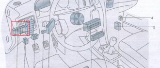
Where are the fuses under the hood of the Mitsubishi Lancer 9
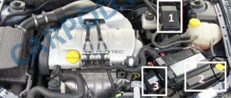
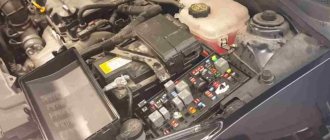
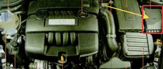
Under the hood, the fuse and relay box can be found on the left side (in the direction of travel of the car). In the image below, the block is numbered 7.
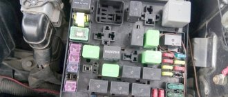
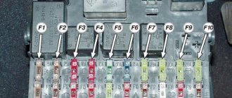
By pressing the latch on the block cover we get to the fuses and relays themselves. It looks like this:
| № | Denomination (A) | Purpose |
| 1 | 15 | Front fog lights, fog light relay power and power indicator |
| 2 | 10 | Sound signal |
| 3 | Relay | Fog light relay |
| 4 | 20 | Mass Air Flow Sensor, Exhaust Gas Recirculation (EGR) Sensor, Electronic Engine Control Unit (ECU), Crankshaft Position Sensor, Idle Speed Control, Ignition Coil Relay, Idle Speed Control, Fuel Injectors, Canister, Engine Cooling Fan Relay |
| 5 | 10 | A/C compressor clutch |
| 6 | Relay | Horn relay |
| 7 | 15 | Electronic engine control unit, ABS control unit, additional brake light and tail lights |
| 8 | Relay | Reserve place |
| 9 | 15 | Additional electrical appliances |
| 10 | Relay | Reserve place |
| 11 | 7,5 | Generator excitation circuit |
| 12 | Relay | Reserve place |
| 13 | 10 | ETACS control unit (responsible for the coordination and correct operation of all electronic systems), direction indicators |
| 14 | 20 | Automatic transmission solenoid control unit |
| 15 | 15 | Lancer 9 fuel pump fuse |
| 16 | Reserve | |
| 17 | 40 | Ignition switch circuit |
| 18 | 30 | Electric windows |
| 19 | 10 | Instrument cluster, steering column switches, ETACS control unit (responsible for the coordination and correct operation of all electronic systems) |
| 20 | 10 | Clock, audio system, ETACS control unit (responsible for the coordination and correct operation of all electronic systems) |
| 21 | 7,5 | Air conditioning control unit, ashtray and cigarette lighter illumination, instrument cluster, rear fog lamp switch, direction indicators, radio connector, |
| 22 | 7,5 | Side lights, license plate lights, instrument cluster |
| 23 | 10 | Low beam lamp, right headlight |
| 24 | 10 | Low beam lamp in the left headlight |
| 25 | Lighting control unit | |
| 26 | Relay | Electric cooling fan relay |
| 27 | 60 | ABS electronic control unit |
| 28 | 50 | Fan controller |
| 29 | 10 | Right headlight high beam lamp and high beam indicator |
| 30 | 10 | High beam lamp in the left headlight |
| 31 | 15 | Front fog lights |
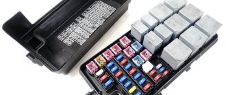
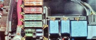
Next to the main fuse box there is an additional relay box:
| № | Purpose |
| 1 | connector for connecting the engine speed indicator; |
| 2 | spare space for relay |
| 3 | Throttle control module relay |
| 4 | spare space for relay |
| 5 | ignition relay |
| 6 | automatic transmission control relay |
| 7 | engine management system main relay |
| 8 | A/C compressor relay |
Sequence of detecting a faulty fuse and replacing it
During the operation of the vehicle, if a malfunction occurs in an individual device or unit of the Mitsubishi Lancer 9, using the tables and figures above, it is necessary to determine the installation location of the fuse(s) serving this device or the system as a whole. Next, with the ignition off, remove this fuse from the connector cell. This is easier to do with the help of special pliers, which are placed in the cover of the removable panel of the interior fuse box. Next, the fuse is checked. This can be done visually. This method is not 100% accurate, so it is better to check the health of the fuse using a multimeter.
If a fuse fails, you must replace it with a known good one of the same rating. Do not install a fuse with an unknown or different rating. It is allowed to temporarily install a fuse that exceeds the nominal value by no more than 25%, for example, 15 Amps instead of 10. Further operation of the vehicle is possible only after replacing it with a standard fuse. Under no circumstances, even temporarily, should a so-called “bug” be used. The consequence of this ill-considered action may be ignition of the electrical wiring.
If, after installing a new fuse and turning on the ignition or subsequent operation of the car, it fails again (burns out), it is necessary to begin examining the electrical equipment of the car and checking the devices that the fuse serves. The constant blowing of one of the fuses is evidence of a faulty wiring, one of the devices that the fuse serves.
As a result of long-term operation of the Mitsubishi Lancer 9 or a traffic accident, there may be cases of failure of the fuse and relay blocks, both in the interior and under the hood. In this case, it is necessary to dismantle and replace them.
Purpose of the relay in the interior fuse box
| № | Purpose |
| 1 | Front fog lamp relay |
| 2 | Reserve space for relay |
| 3 | Electric fuel pump relay No. 2 |
| 4 | Heated front seats relay |
| 5 | Electric fuel pump relay No. 1 |
| 6 | Power window relay |
| 7 | |
| 8 | Electric Cooling Fan Relay |
| 9 | Heated rear window relay |
Removing the cigarette lighter Lancer 10
On next-generation cars, repairs are carried out differently. The set of tools remains the same. In order to remove the cigarette lighter on the Lancer 10 model, you need to follow the steps.
Sometimes it is possible to repair a Lancer device directly on site, with your own hands. To do this, you need to examine the back of the device. Often the wire coming into the structure burns out and the fuse trips. “Swelling” of the insulation will help detect this malfunction. Using a key, we disassemble the back part, remove the burnt wires and insert a new copper wire into the holes. Then we assemble the part in reverse order and diagnose its serviceability.
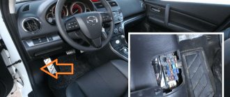
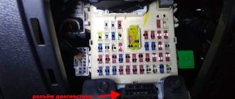
Assignment of fuses in the cabin
| № | Denomination (A) | Purpose |
| 10 | 30 | Electronic air conditioning control unit |
| 11 | 30 | Electrical control unit for air conditioning |
| 12 | 7,5 | Joystick for controlling rear view mirrors |
| 13 | 7,5 | ABS electronic control unit |
| 14 | Spare | |
| 15 | 7,5 | Air conditioning compressor relay, air distribution selector motor, automatic transmission electronic control unit relay, rear window defroster relay, heater, heater relay, |
| 16 | 7,5 | Auxiliary relay and exterior mirror control |
| 17 | Backup fuse | |
| 18 | Backup fuse | |
| 19 | Backup fuse | |
| 20 | 10 | Rear fog light |
| 21 | 7,5 | Automatic transmission control relay, Supplemental Restraint System (SRS) electronic control unit, engine and automatic transmission electronic control unit (for vehicles with automatic transmission), instrument cluster, ETACS electronic control unit, output shaft speed sensors (for vehicles with automatic transmission ), reverse light, |
| 22 | 15 | Cigarette lighter fuse Mitsubishi Lancer 9 |
| 23 | 15 | Diagnostic connector |
| 24 | 7,5 | Battery lamps, ABS, CHECK ENGINE, SRS, oil pressure and brake system status lamps on the instrument panel, instrument cluster, ETACS electronic control unit, speed sensor |
| 25 | 7,5 | Electronic engine and automatic transmission control unit (for vehicles with automatic transmission), electronic engine control unit, fuel pump relay No. 1, fuel pump relay No. 2 |
| 26 | 15 | ETACS electronic control unit and rear window wiper motor (station wagon) |
| 27 | 10 | Capacitor (for 4G6 engines), ignition coils |
| 28 | 20 | Electronic lighting control unit, windshield wiper |
| 29 | Backup fuse |
The process of replacing the cigarette lighter on a Mitsubishi Lancer 9
Options from different companies are available for sale. If repairing the cigarette lighter is impractical, it can be replaced with a new device. The price of the device for lancer x and other models is 500 – 1000 rubles, depending on the company or country of manufacture.
If you need to replace the cigarette lighter on Lancer 9, when choosing, you should avoid spare parts that are too cheap. Most likely, low-quality materials were used in their manufacture, so such a part will not last long. It is best to choose original cigarette lighters. The part must be carefully packaged, and inside there is a certificate of conformity class=”aligncenter” width=”600″ height=”426″[/img]
The main relay does not operate. The internal combustion engine does not start. CHEK is not lit
The main relay does not operate. The internal combustion engine does not start. CHEK is not lit
bullet » Mon, 26 Mar 2012 18:02
Re: Main relay does not work. The internal combustion engine does not start. CHEK is not lit
granda » Mon, 26 Mar 2012 19:51
Re: Main relay does not work. The internal combustion engine does not start. CHEK is not lit
bullet » Tue, Mar 27, 2012 2:24 am
Re: Main relay does not work. The internal combustion engine does not start. CHEK is not lit
vnizam » Tue, Mar 27, 2012 9:14 am
What is the most important thing in Mitsubishi. That's right!, the most important thing in Mitsubishi is not to shit yourself.
Re: Main relay does not work. The internal combustion engine does not start. CHEK is not lit
bullet » Tue, 27 Mar 2012 12:21
Re: Main relay does not work. The internal combustion engine does not start. CHEK is not lit
vnizam » Tue, 27 Mar 2012 13:35
What is the most important thing in Mitsubishi. That's right!, the most important thing in Mitsubishi is not to shit yourself.
Re: Main relay does not work. The internal combustion engine does not start. CHEK is not lit
bullet » Wed, 28 Mar 2012 14:19
Re: Main relay does not work. The internal combustion engine does not start. CHEK is not lit
first » Wed, 28 Mar 2012 16:09
Re: Main relay does not work. The internal combustion engine does not start. CHEK is not lit
vnizam » Wed, 28 Mar 2012 19:18
Can you show this relay on the diagram, for some reason I can’t find it.
Added after 52 minutes 52 seconds: I found it here
but just look there, if all the previous ones are intact, then look for a broken wire!
What is the most important thing in Mitsubishi. That's right!, the most important thing in Mitsubishi is not to shit yourself.
Re: Main relay does not work. The internal combustion engine does not start. CHEK is not lit
bullet » Thu, 29 Mar 2012 16:10
49 wire was checked for a break with a tester; it was intact. The main relay is activated when a potential difference occurs at the beginning of the main relay coil, wire No. 2, and at the end of the coil, wire No. 3. When the ignition is turned off, the voltage on wire 49 is 12V and therefore there is no potential difference between the coils and the contact between wires 1-4 is open. When the ignition is turned on, the base of the transistor located in the ECU block (wire No. 49 is indicated below in the diagram) receives power from a wire unknown to me, while the PNP or NPN junction opens, a potential difference occurs and contact 1-4 closes. In addition, this same unknown wire opens some other transistors in the ECU that are responsible for triggering the remote control, MAF, etc. I made this conclusion from the fact that when installing a jumper (pulling out the relay) between wires 1-4, neither the remote control servo drive nor anything else receives power.
Added after 4 minutes 15 seconds: firt - I didn’t understand where these fuses are located. Above the fuse box in the spit?
Re: Main relay does not work. The internal combustion engine does not start. CHEK is not lit
C00LM4N » Thu, 29 Mar 2012 16:22
Re: Main relay does not work. The internal combustion engine does not start. CHEK is not lit
first » Thu, 29 Mar 2012 16:58
Re: Main relay does not work. The internal combustion engine does not start. CHEK is not lit
bullet » Tue, 03 Apr 2012 13:15
first I don’t have such prevs. Maybe you installed these presets along with the alarm system.
Added after 57 minutes 40 seconds: C00LM4N I also checked the version about the ignition switch (to fuses 1-5 in the cabin, power is supplied), so I think the problem is still in the ECU. I already changed one ECU unit at the beginning of this epic, but it also seemed to be finished. Tomorrow I will have a tested unit.
Re: Main relay does not work. The internal combustion engine does not start. CHEK is not lit
bullet » Thu, 05 Apr 2012 17:56
Mitsubishi ASX Club
Mitsubishi ASX Owners Club Forum
- Links
- Unanswered messages
- Active topics
- Search
- our team
urgently! Both cigarette lighters don't work, I'm on the road
- print version
urgently! Both cigarette lighters don't work, I'm on the road
- Quote
#1
Post by Madmax » Jul 12, 2013, 6:02 pm
- Quote
#2
Post by LEXA25 » Jul 12, 2013, 6:16 pm
I found it on another forum
If your cigarette lighter (socket) does not work: The car has: 1 cigarette lighter, 1 additional socket in the armrest and 1 additional socket in the trunk on the right side.
If at least one of the listed components does not work, check: 1. Turn on the ignition (either the first position or start the car) - the cigarette lighter (additional sockets) and other electrical equipment only work when the key is in “I” or when the car is started 2. If the cigarette lighters do not work, check the fuses in the fuse box - No. 13 (cigarette lighter) and No. 19 (sockets) 3. If the fuses are intact (replace with new ones, just in case), you need to check the fuse INSIDE the cigarette lighter next to the ashtray. How to get to the inside of the cigarette lighter - see paragraph 2 How to disassemble the center console. Photo report 4. If the fuse there is intact, then you either need to look at the wiring or the cigarette lighter sockets themselves for integrity, operability and absence of damage. It seems like there are no more options.
Step-by-step replacement instructions
Mitsubishi Lancer 10 cigarette lighter: why it doesn’t work, how to replace
The hoses, which are visible in the photo above, should be carefully removed. You will also need to disconnect the wiring plug.
Attention. It will be more difficult to remove a fuel hose secured with a latch
It will take some effort to get her to give in.
Further actions:
the fastening nuts installed around the entire circumference of the fuel cleaning element are turned out;
Nuts around the entire circumference of the cover
the module is lifted (removed) upward.
You must remove the filter with the submersible pump very carefully so as not to inadvertently bend the float with its fastening (the black float is shown in the photo below).
TF float with its mount
In order to disconnect the TF from the module, you need to:
- press the clips in the places shown in the photo below and the plugs will come out easily;
- using pliers, squeeze out the protective ring to separate the filter from the module;
- raise the top of the module;
- release the TF from the wires;
- replace the old filter with a new one.
The coarse mesh or tea bag is also changed.
New filter Lancer 10
Gasoline pump
Gasoline pump
#1 Unread message MobileMan » Wed Oct 03, 2012 1:49 pm
#2 Unread message leonec » Tue Oct 30, 2012 11:14 am
#3 Unread message LancerZ » Tue Oct 30, 2012 12:55 pm
#4 Unread message MobileMan » Tue Oct 30, 2012 1:05 pm
No matter how much I looked for information about the performance of Lancer pumps, I couldn’t find it. and the markings on the original pump are also nowhere to be seen
I’ll assume that the pump from 1.5 is different from 1.8 -2.0.
#5 Unread message LancerZ » Tue Oct 30, 2012 1:16 pm
#6 Unread message leonec » Tue Oct 30, 2012 1:27 pm
#7 Unread message MobileMan » Tue Oct 30, 2012 1:31 pm
#8 Unread message LancerZ » Tue Oct 30, 2012 1:36 pm
#9 Unread message MobileMan » Tue Oct 30, 2012 1:48 pm
#10 Unread message LancerZ » Tue Oct 30, 2012 1:58 pm
Well, what was your question in the previous message?
One and a half - VAZ is enough for her.
#12 Unread message temba » Tue Oct 30, 2012 2:45 pm
1.5 – 1760A271 2.0 – 1760A271
find 10 differences)) Identical pump assemblies are listed in the catalog!
temba wrote: 1.5 – 1760A271 2.0 – 1760A271
find 10 differences)) Identical pump assemblies are listed in the catalog!
#14 Unread message LancerZ » Tue Oct 30, 2012 5:56 pm
#15 Unread message LancerZ » Fri Nov 09, 2012 8:56 am
For those who do not accept OEM Denso used, here is a likely replacement:
Airtex Electric Fuel Pump – E8548
According to the characteristics, according to unverified information (the manufacturer is silent), it is not very bad:
“GPH (Free Flow) Rating: 45-55 gph Hardware Included: Yes Marine Approved: No Pressure Rating: 70-90 PSI”
But I am for Denso, because it is reliability and quality.
How to change generator bearings yourself?
Bearing Replacement Process In order to replace the bearings, you will first need to completely remove the alternator from the vehicle.
We begin the work by disconnecting the battery terminals. The following is a simple procedure for disassembling this device to access the parts themselves:
- unscrew the cover mounting bolts (there are 4 of them);
- separate the halves by tapping on the locking “ears”;
- lightly clamp the rotor in a vice at the special triangular places on it (but not at the pulley, it will be damaged in the end);
- unscrew the nut and remove the pulley with the spacer;
- remove the rotor from the cover;
Disassembly is complete, now you can start replacing the bearings themselves. To change the front part, you just need to unscrew the 4 bolts on the cover. But you'll have to tinker with the back one. It needs to be pressed off the rotor shaft. Reassembling the device is carried out in the reverse order.
Price issue
It is better to select new spare parts from the manufacturer. They are more reliable and perfect for installation in a car. As for the cost, the belt can be found for about 1000 rubles. Bearings, both front and rear, can be found on the Internet for 300 rubles.