Purpose of the Volkswagen Jetta fuse box (VW Jetta) - almost the entire Volkswagen Jetta power circuit system, on which the operation of the vehicle’s equipment depends, is protected by fusible contact elements, which are combined into the so-called fuse box. The following energy consumers are connected to the relays, which are also part of this unit:
- lighting lanterns;
- cooling fan motors;
- fuel pump and so on
This unit and its maintenance are of particular importance for the stable operation of the main systems of the Volkswagen Jetta model. Therefore, these contact elements are combined and placed in a special mounting block. According to the instructions, it is located in the Volkswagen Jetta interior, on the left side of the dashboard. There is an upper shelf, which in turn consists of:
- lower dashboard cover;
- mounting screw;
- dashboard;
- cover protecting the unit.
Attaching the top shelf to a Volkswagen Jetta
This is where the block is located, where in case of a malfunction you need to look. As a rule, a faulty or burnt contact element will break. It will have a die-cast metal piece with a black finish. It is also possible that the color of the housing may be distorted.
Volkswagen Jetta fuse box: diagram
A faulty device will immediately be noticeable by its melted part and black coating. Location and location Removal and replacement process How to find a blown fuse and replace it When choosing a protection device, consider its rated voltage, which should not be less than the mains voltage and system current.
The protective devices installed in the motor circuits are controlled by the motor starting current. The protective elements are checked with a tester when there is no need to remove the element from the socket.
If you find a burnt-out component, it should be replaced with one that meets the current rating. Every driver must have a set of protective spare parts.
Removing and replacing protective parts Before replacing the protective element, turn off the ignition so that its holder does not become damaged. Finding a burnt-out device that prevents a dangerous action is not easy.
Software way to disable headlight washers
The second way you can independently disable the headlight washers on a Volkswagen Jetta is a diagnostic adapter, which today can be purchased through any online store. It allows you to programmatically, through long coding in block 09 “Botnet Management”, disable any function of the car. So, let's consider the decision-making algorithm when working with an adapter:
- After the device is connected and a menu with a digital designation of all the car’s blocks appears on the screen, we go to the ninth block of interest to us.
- Next, in the service functions, select 07 coding.
- In automated mode, the model and nomenclature of the VW Jetta unit will be displayed. To be careful, it is better to copy the data onto a piece of paper, since in case of any consequences, you can return everything back.
- Below will be the “Long Coding” key, which you need to press, thereby opening the code for the headlight washer function.
- Then we move the arrow to the cell of the first byte of the encoded information and uncheck the first bit.
- Next, the program will ask you to confirm the changes made to the program code, so we give our consent to the actions and close the program.
It is worth remembering that if you do not have relevant experience working with a diagnostic adapter, then it is better not to take risks, since incorrect coding can completely damage the control unit.
Volkswagen Jetta 6 fuses
The sixth generation Volkswagen Jetta was produced from 2010 to 2016. The protection of the electrical system and its components consists of relays and fuses. For ease of maintenance, they are assembled into several separate modules.
Cabin module of fusible elements
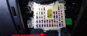
To access the fifth generation Volkswagen Jetta cabin module fuses, the driver's door must be open and locked. There is a fuse cover on the side of the instrument panel. To open it, you need to pry the outer edge with a screwdriver and pull it out.
PP cabin block pinout
Protected circuit or electrical equipment Rating, A Color coding No.
| Connector not used | 1 | ||
| Steering column switches | 5 | Light yellow | 2 |
| OBDII connector for diagnostics | 5 | Light yellow | 3 |
| ABS system unit, electronic components | thirty | Light green | 4 |
| Automatic transmission controller | 15 | Blue | 5 |
| Tools on the panel | 5 | Light yellow | 6 |
| Connector not used | 7 | ||
| Radio in the center console | 15 | Blue | eight |
| GSM phone | 5 | Light yellow | nine |
| Engine controller, relay | 5 | Light yellow | 10 |
| Internal Heater Fan Controller, Auxiliary Heater Controller | winds | Yellow | eleven |
| OBDII diagnostic bus controller | 5 | Light yellow | 12 |
| ECU, engine controller | 15 | Blue | 13 |
| Relay + 12V on-board network | winds | Yellow | 14 |
| Exhaust gas oxygen sensor, fuel pump, diesel internal combustion engine glow plugs | 15 | Blue | 15 |
| ABS system unit, electronic components | thirty | Light green | 16 |
| Horn | 15 | Blue | 17 |
| OEM audio amplifier | thirty | Light green | 18 |
| Wipers | thirty | Light green | 19 |
| Connector not used | winds | ||
| + 12V heated lambda probe | 15 | Blue | 21 years old |
| Brake pedal switch, clutch pedal switch | 5 | Light yellow | 22 |
| Intake manifold air recirculation pump, high pressure fuel pump, air flow sensor (DFID) | 10 | Red | 23 |
| EGR valve | 10 | Red | 24 |
| Headlight, right side | thirty | Light green | 25 |
| Headlight, left side | thirty | Light green | 26 year |
| Air recirculation pump in the intake manifold, engine warm-up mode | 40 | Orange | 27 |
| Engine starter relay | 40 | Orange | 28 year |
| + 12V at pin 30 | 40 | Orange | 29 |
| Contact X | 40 | Orange | thirty |
| Auxiliary cooling fan motor relay | R1 | ||
| Automatic transmission controller relay | R2 |
Fuse box
Located under the panel. Remove the protective cover for access.
Photo - example
Scheme
Designation
Option 1
Fuse No. 30 at 20A is responsible for the cigarette lighter.
Option 2
| F1 | (10A) Washing machine jet heating resistance |
| F2 | (5A / 7.5A) Steering lock |
| F3 | (10A) Instrument panel |
| F4 | (2A/10A) Telephone receiver/transmitter |
| F5 | (7.5A) Left rear fog lamp |
| F6 | (10A) Multifunction control unit, rear view camera |
| F7 | (5A) Fog light relay, switch and instrument panel light control, license plate light |
| F8 | (7.5A) Windshield washer pump and headlight switch, windshield washer pump |
| F9 | (5A) Airbag control unit, (15A) Seat occupied recognition control unit |
| F10 | (10A) Right steering column switch |
| F11 | (10A) left headlight, (discharge headlight) |
| F12 | (10A) right headlight, (discharge headlight) |
| F13 | (5A) Electrochromic interior mirror, light sensor, parking assist control unit, air pollution sensor, high pressure sensor, Climatronic control unit, tire pressure monitoring button, ASR and ESP switch off button, reverse light switch, start-stop switch , heating resistance for the left washer nozzle, heating element for the right nozzle, mirror adjustment switch, exterior mirror heating button, control unit for adaptive lighting and headlight depth adjustment |
| F14 | (10A) Left steering column switch, ABS control unit, fuel pump control unit, trailer recognition control unit, voltage stabilizer, inverter with socket, 12 V - 230 V, data bus diagnostic interface |
| F15 | (10A) Connector, 16-pin, (diagnostic connector), instrument panel light switch and control, headlight trim control, fresh air fan relay, air flow meter, crankcase ventilation heater, vibration damping control unit, left headlight, left headlight trim control control , right headlight, right headlight depth adjustment actuator |
| F16 | (10A) Auxiliary coolant pump, fuel pump, engine key relay. |
| F17 | (10A) Anti-theft system and corresponding relay |
| F18 | (15A) Left headlight |
| F19 | (15A) Right headlight |
| F20 | (10A) Ignition and starter switch, Tiptronic switch, automatic transmission control unit, selector lever sensor control unit, Climatronic control unit, radio for additional water heater |
| F21 | (15A / 20A) On-board power supply control unit, two-tone horn relay, high tone horn, low tone horn |
| F22 | (7.5 A / 20 A) Ignition and Starter Switch, Converter, Internal Sensor, Hazard Siren Relay, Anti-Theft Horn |
| F23 | (10A) On-board power supply control unit, light switch, rain and light sensor, magnetic field sensor for compass |
| F24 | (10A) Adaptive lighting and headlight range control module |
| F25 | (15A) Transmission, automatic gear shift |
| F26 | (15A) Brake booster vacuum pump |
| F27 | (1A) Airbag spiral cable with slip ring |
| F28 | (40A) Auxiliary heater activation relay |
| F29 | (1A) Multi-function control unit, ignition and starter switch |
| F30 | (20A) Cigarette lighter sockets |
| F31 | (30A) Light switch |
| F32 | (20A) Light switch |
| F33 | (40A) Heater and operating mode switch, fresh air fan relay, air conditioning control unit, fresh air fan switch |
| F34 | (15A) Left high beam lamp, right high beam lamp, instrument panel control unit |
| F35 | (10A) Steering column control unit, data bus diagnostic interface, horn switch |
| F36 | (25A) Multifunction control unit |
| F37 | (15A) left headlight, left lamp |
| F38 | (15A) Right headlight, right daytime running light |
| F39 | (20A) Low beam relay |
| F40 | (15A) Trailer control module |
| F41 | (15A) Trailer control module |
| F42 | (20A) Trailer control module |
| F43 | (30A) Passenger door control unit |
| F44 | (30A) Heated rear window relay, heated rear window, on-board power supply control unit |
| F45 | (30A) Driver door control unit, front passenger door control unit |
| F46 | (30A) Rear left door control unit, rear right door control unit |
| F47 | (15A) Fuel pump |
| F48 | (20A) Multifunction control unit |
| F49 | (40A) Fresh air fan, Climatronic control unit |
| F50 | (30A) Heated seats |
| F51 | (20A) Hatch |
| F52 | (20A) Horn |
| F53 | (15A) Driver's seat lumbar support adjustment switch |
| F54 | (15A) Fog lamp relay |
| F55 | (20A) Light switch, left steering column switch |
| F56 | (10A) Electric drive and power control electronics |
| F57 | (15A / 25A) Audio system, navigation system |
| F58 | (30A) Inverter with socket, 12V |
| F59 | (15A) Fan relay, battery |
| F60 | (30A) Additional heater control unit |
Fuse No. 30 at 20A is responsible for the cigarette lighter.
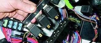
Relay block
Located above the fuse box.
Basic
Scheme
Designation
| 1 | — |
| 2 | Heated mirror relay |
| 3 | — |
| 4 | Multifunction control unit relay |
| 5 | Heated rear window relay |
| 6 | Horn relay |
| 7 | Windshield washer pump relay 1 |
| eight | Windshield washer pump relay 2 |
| nine | Auxiliary Ignition Relay |
Additional
Scheme
Business date, meeting
| 1 | Headlight washer pump relay |
| 2 | Fuel lift pump relay - Diesel |
| 3 | Starter relay |
| 4 | Headlight washer pump relay |
| 5a | Starter relay (fuel system) |
| 5b | Auxiliary heater relay |
| A | Fuse 1 30A for driver's seat adjustment |
| IN | Driver's seat adjustment with 30A fuse 2 |
Block Z13
| Number | Business date, meeting |
| 1 | Additional fan for air conditioner |
| 2 | Clutch (clutch) |
| 3 | Air conditioner switching elements |
| 4 | Air conditioning |
| 5 | Fuel pump in diesel versions |
| 6 | Outdoor Lighting) |
| 7 | Front optics |
| eight | "Candles" |
| 10 | PTF |
| eleven | Connection |
| 12 | Starter |
| 13 | Anti-theft lock |
Block R
| Number | Business date, meeting |
| IN | Sound signal |
| II | Relay in contact X |
| III | Window washers |
| IV | Fuel pump, “spark plugs” |
| A | Connector 1 in trunk |
| B | Connector 2 in trunk |
Block Z8
| Number | Business date, meeting |
| 2 | ABS/EDS/ESC |
| 3 | ABS/EDS/ESC |
| 4 | Fan 1 stage |
| 5 | Fan at maximum |
| 6 | Fan for 2nd stage |
| A | Fan |
| B | Fan |
| WITH | Hydraulic pump |
Block under the "tidy"
| Number | Business date, meeting |
| 1 | "Stove" (additional) |
| 3 | Fan providing additional air supply |
| 5 | Fuel pump (diesel) |
| 6 | Optical washer |
| 7 | Pin voltage 50 |
On the Passat B7, the electronic transmission systems relay is located in a block next to the battery. There is also an additional section with a similar element for “candles”.
There are three blocks with relays on the panel inside the machine. The first contains elements for the stove fan and crankcase ventilation resistance. The second relay contains an additional “battery”. The third block contains a rear window heating relay and a similar element of auxiliary ignition circuits.
Relay subblock: option No. 1
Circuit number Circuit served
| 1 | control unit with ignition switch |
| 2-4 | Not used |
| 5 | Headlight switch |
| 6 | Not used |
| 7 | Auxiliary ignition circuits |
| eight | Sound signal |
| nine | Headlight washer pump |
| 10.11 | Not used |
| 12 | Heated rear window |
| 13-15 | Not used |
| 16 | Fog lights |
Option 2
- R1 – Two-tone signal relay, headlight washer relay
- R2 – power relay (pin 50), starter relay 2
- R3 – Fuel pump relay, cold start relay
- R4 – Coolant circulation pump relay, fuel pump relay
- R5 – terminal 75, power relay 1
- R6 – Power relay (pin 50), starter relay
- R7 – Terminal 15, power relay
- R8 – Low beam relay
- R9 – Terminal 15, power relay 2
- R10 – terminal 75, power relay 1, stroke change
- R11 – Fog lamp relay, fan relay
- R12 – Converter
Relay subblock: option No. 3
Circuit number Circuit served
| 1-11 | Not used |
| 12 | Auxiliary Ignition Relay |
| 13 | Not used |
| 14 | control unit with ignition switch |
Block under the hood
It is located on the right side next to the battery and covered with a protective cover.
| F1 | |
| F2 | (10A / 15A) Motor control, motor electronics power relay |
| F3 | (5A) Cooling fan motor, heating relay |
| F4 | (5A / 10A / 15A) Engine management, coolant pump, lambda probe heater |
| F5 | (5A / 10A / 20A) Lambda probe resistance, fuel diagnostic pump, air flow meter, brake vacuum pump |
| F6 | (5A / 10A / 15A) Fuel system diagnostic pump, fuel tank shut-off valve, secondary air pump relay |
| F7 | (5A/20A) Engine Control (Ignition Coil), Fuel Pressure Regulator |
| F8 | (10A) Engine control (throttle body, wastegate, clutch pressure regulator..) |
| F9 | (5A / 15A) Glow plug control unit, fuel pump relay |
| F10 | (5A) Speed Sensor, Brake Light Switch, Brake Power Relay |
| F11 | |
| F12 | (5A/20A) Coolant circulation pump, ignition coil |
| F13 | (5A) Water pump (20A) Brake booster relay |
| F14 | (5A) Motor control, main relay |
| F15 | (30A) Voltage Regulator Box |
| F16 | (30A) ABS/ESP system |
| F17 | (30A) Transmission |
| F18 | (20A) DSG mechatronics unit |
| F19 | (1A) Multifunction control unit |
| F20 | (30A) Wiper and washer relay |
| F21 | (50A) Exhaust air pump |
| F22 | (40A) Air heater auxiliary heater |
| F23 | (40A) ABS/ESP system |
| F24 | (50A) Trailer control module |
| F25 | (50A) Main ignition circuits, power relay terminal 15 |
| F26 | (60A) Glow plugs (40A) Secondary air pump relay |
| F27 | (50/60A) Cooling fan motor |
| F28 | (40A) Multifunction control unit |
| F29 | (40A) Multifunction control unit |
| F30 | (50A) Auxiliary circuits |
| F31 | (30A) Audio output amplifier |
| F32 | (40A) Coolant heater |
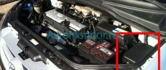
Underhood fuse module
The ECU and relay in the engine compartment have six relay connectors and 37 fuse slots. Not all slots are used, some of them are optional.
Location of fuses in the motor module.
Secure network or device Rating, A Color coding Diagram number
| Relay connector | R1 | ||
| Relay connector | R2 | ||
| Relay connector | R3 | ||
| Relay connector | R4 | ||
| Relay connector | R5 | ||
| Relay connector | R6 | ||
| Not used | 1 | ||
| Engine control unit | 10,15 | red blue | 2 |
| Engine Radiator Fan Relay | 5 | Brown | 3 |
| Engine control unit | 5, 10, 15 | Brown, red, blue | 4 |
| Spare fuse | 5, 10, 15 | Brown, red, blue | 5 |
| Spare fuse | 5, 10, 15 | Brown, red, blue | 6 |
| Engine controller | 5 20 | Brown, yellow | 7 |
| Engine controller | 10 | Red | eight |
| Glow plug regulator for diesel internal combustion engines, fuel pump relay | 5,15 | Brown, blue | nine |
| Brake light switch, speed sensor | 5 | Brown | 10 |
| Not used | eleven | ||
| Additional engine coolant pump | 5 20 | Brown, yellow | 12 |
| Main Engine Coolant Pump | 5 | Brown | 13 |
| Engine start control unit | 5 | Brown | 14 |
| On-board voltage regulator | thirty | Green | 15 |
| ESP traction control system, ABS system | thirty | Green | 16 |
| Automatic transmission | thirty | Green | 17 |
| Manual Transmission | winds | Yellow | 18 |
| Embedded Network Controller Switch | 1 | 19 | |
| Front wiper relay, +12 V for windshield washer | thirty | Green | winds |
| Intake manifold motor | 50 | Red | 21 years old |
| Not used | 22 | ||
| ESP traction control system, ABS system | 40 | Green | 23 |
| Trailer power and connection controller | 50 | Red | 24 |
| Mains ignition system, gasoline internal combustion engines | 50 | Red | 25 |
| Glow plugs, diesel internal combustion engines | 60 | 26 year | |
| Additional engine radiator fan | 60 | 27 | |
| ECU, main engine controller | 40 | Green | 28 year |
| ECU, main engine controller | 40 | Green | 29 |
| Additional electrical circuits on board | 50 | Red | thirty |
| OEM audio amplifier | thirty | Green | 31 year |
| Additional heating of Webasto coolant | 40 | Green | 32 |
| Not used | 33 | ||
| Generator protection | 200 | 34 | |
| Not used | 35 year | ||
| Electric power steering column | 80 | 36 | |
| Spare fuse | 80 | 37 |
Relay purpose
- Secondary air pump relay
- Coolant pump relay
- Air supply relay, terminal 30 power supply relay
- —
- —
- Glow plug relay
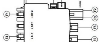
Fuse link department
High-power fuses in the form of fuse links are located on the side of the installation.
Scheme
Designation
- 508 – threaded connection (30) on the switching block
- SA1 – Generator 200A
- SA2—
- SA3 – 80A Steering
- CA4 – 80A Salon, class. 30, power supply fuses
Headlight washer fuse
A headlight washer is an extremely useful device, especially when it comes to driving at night or traveling through rain and mud. Don't worry in such bad weather because the headlight washer guarantees the flow of light.
The light from the headlights should be clear and bright. However, due to headlight washing, fluid consumption may increase. Many drivers turn off the fuse of the optical washing machine at the first frost, so as not to turn on the device under the influence of temptation.
But this device can also fail. Don't forget that the headlight washer is also responsible for its protective element. If the headlight washer fails, check the protective element and replace it if necessary.
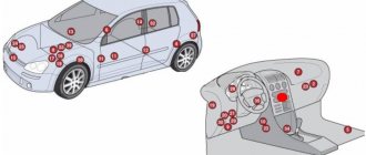
General arrangement of control units
Scheme
Description
| 1 | ABS electronic control unit |
| 2 | Electronic air conditioner control unit |
| 3 | Accumulator battery |
| 4 | Diagnostic connector (DLC) |
| 5 | Diagnostic block |
| 6 | Driver's door electrical control unit |
| 7 | Left rear door electrical control unit |
| 8 | Passenger door electrical control unit |
| 9 | Right rear door electrical control unit |
| 10 | Electronic Engine Control Module (ECM) |
| 11 | Fuse/Relay Box, Engine Compartment |
| 12 | Fuse/Relay Box, Instrument Panel 1 |
| 13 | Fuse/Relay Box, Instrument Panel 2 |
| 14 | Glow plug control unit - under the fuse/relay box in the engine compartment |
| 15 | Headlight range control unit |
| 16 | Heater Blower Motor Resistor - Next to Heater Blower Motor |
| 17 | Sound signal |
| 18 | Ignition switch control unit (some models) - in instrument panel fuse/relay box 2 |
| 19 | Control unit for remote control of central locking and engine start |
| 20 | Multifunctional control unit - functions: Anti-theft system, central locking, charging system, door function control units, electrical load control, exterior lamps, footwell lamps, fuel filler flap actuator, fuel pump, rear view mirror heater, rear window defroster, horn, immobilizer, turn signals/hazard warning lights, instrument cluster lights, interior lights, remote central locking and engine start, rain/sunlight sensor, brake lights, windshield wiper/washer |
| 21 | Parking system control unit |
| 22 | Power steering control unit - on the steering rack |
| 23 | Seat heating control unit - under the driver's seat |
| 24 | Steering column electrical control unit |
| 25 | Steering column lock control unit |
| 26 | Electronic control unit SRS |
| 27 | Trailer electrical control unit |
| 28 | Electronic transmission control module (TCM) (DSG transmission) |
| 29 | Electronic Transmission Control Module (TCM) - Automatic Transmission |
| 30 | Voltage stabilizer block |
Volkswagen Jetta 5 fuses
To prevent damage to electrical devices or vehicle circuits, the fifth generation Volkswagen Jetta, produced from 2005 to 2010, uses fuses and fuses. They are located in modular blocks along with the relays.
Where are the fuse boxes located?
In the VolksWagen Jetta 5, the manufacturer assembled all the fuses in two blocks:
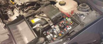
- Engine block - located in the engine compartment on the driver's side, next to the brake fluid expansion tank.
- Interior module - located on the side of the instrument panel on the driver's side.
Underhood fuse module
To access the fuse and relay motor module, you must move the cover fastening elements towards the vehicle and remove it. After checking and replacing the board, you need to replace the cover, return the clamps to their original position and make sure that the unit is tightened well.
Location of fuses in the motor module.
Protected circuit or electrical equipment Rating, A Color coding No.
| Connector not used | 1 | ||
| Steering column switches | 5 | Light yellow | 2 |
| OBDII connector for diagnostics | 5 | Light yellow | 3 |
| ABS system unit, electronic components | thirty | Light green | 4 |
| Automatic transmission controller | 15 | Blue | 5 |
| Tools on the panel | 5 | Light yellow | 6 |
| Connector not used | 7 | ||
| Radio in the center console | 15 | Blue | eight |
| GSM phone | 5 | Light yellow | nine |
| Engine controller, relay | 5 | Light yellow | 10 |
| Internal Heater Fan Controller, Auxiliary Heater Controller | winds | Yellow | eleven |
| OBDII diagnostic bus controller | 5 | Light yellow | 12 |
| ECU, engine controller | 15 | Blue | 13 |
| Relay + 12V on-board network | winds | Yellow | 14 |
| Exhaust gas oxygen sensor, fuel pump, diesel internal combustion engine glow plugs | 15 | Blue | 15 |
| ABS system unit, electronic components | thirty | Light green | 16 |
| Horn | 15 | Blue | 17 |
| OEM audio amplifier | thirty | Light green | 18 |
| Wipers | thirty | Light green | 19 |
| Connector not used | winds | ||
| + 12V heated lambda probe | 15 | Blue | 21 years old |
| Brake pedal switch, clutch pedal switch | 5 | Light yellow | 22 |
| Intake manifold air recirculation pump, high pressure fuel pump, air flow sensor (DFID) | 10 | Red | 23 |
| EGR valve | 10 | Red | 24 |
| Headlight, right side | thirty | Light green | 25 |
| Headlight, left side | thirty | Light green | 26 year |
| Air recirculation pump in the intake manifold, engine warm-up mode | 40 | Orange | 27 |
| Engine starter relay | 40 | Orange | 28 year |
| + 12V at pin 30 | 40 | Orange | 29 |
| Contact X | 40 | Orange | thirty |
| Auxiliary cooling fan motor relay | R1 | ||
| Automatic transmission controller relay | R2 |
Cabin module of fusible elements
To access the fifth generation Volkswagen Jetta cabin module fuses, the driver's door must be open and locked. There is a fuse cover on the side of the instrument panel. To open it, you need to pry the outer edge with a screwdriver and pull it out.
PP cabin block pinout
Protected circuit or electrical equipment Rating, A Color coding No.
| Connector not used | 1 | ||
| Steering column switches | 5 | Light yellow | 2 |
| OBDII connector for diagnostics | 5 | Light yellow | 3 |
| ABS system unit, electronic components | thirty | Light green | 4 |
| Automatic transmission controller | 15 | Blue | 5 |
| Tools on the panel | 5 | Light yellow | 6 |
| Connector not used | 7 | ||
| Radio in the center console | 15 | Blue | eight |
| GSM phone | 5 | Light yellow | nine |
| Engine controller, relay | 5 | Light yellow | 10 |
| Internal Heater Fan Controller, Auxiliary Heater Controller | winds | Yellow | eleven |
| OBDII diagnostic bus controller | 5 | Light yellow | 12 |
| ECU, engine controller | 15 | Blue | 13 |
| Relay + 12V on-board network | winds | Yellow | 14 |
| Exhaust gas oxygen sensor, fuel pump, diesel internal combustion engine glow plugs | 15 | Blue | 15 |
| ABS system unit, electronic components | thirty | Light green | 16 |
| Horn | 15 | Blue | 17 |
| OEM audio amplifier | thirty | Light green | 18 |
| Wipers | thirty | Light green | 19 |
| Connector not used | winds | ||
| + 12V heated lambda probe | 15 | Blue | 21 years old |
| Brake pedal switch, clutch pedal switch | 5 | Light yellow | 22 |
| Intake manifold air recirculation pump, high pressure fuel pump, air flow sensor (DFID) | 10 | Red | 23 |
| EGR valve | 10 | Red | 24 |
| Headlight, right side | thirty | Light green | 25 |
| Headlight, left side | thirty | Light green | 26 year |
| Air recirculation pump in the intake manifold, engine warm-up mode | 40 | Orange | 27 |
| Engine starter relay | 40 | Orange | 28 year |
| + 12V at pin 30 | 40 | Orange | 29 |
| Contact X | 40 | Orange | thirty |
| Auxiliary cooling fan motor relay | R1 | ||
| Automatic transmission controller relay | R2 |
Internal fuse block
The interior fuse module does not have connectors for relays, but consists only of PCBs. It is quite compact and easy to maintain.
| Protected electrical network or device | Nominal value, A | Color coding | Number on the diagram |
| Not used | 1 | ||
| Steering wheel lock | 5, 7,5 | Brown | 2 |
| Instruments on the panel | 10 | Red | 3 |
| GSM phone antenna | 2 10 | Red | 4 |
| Rear fog lamp, left side | 7.5 | Brown | 5 |
| Multifunction controller | 10 | Red | 6 |
| Brightness of instruments and buttons, fog lamp relay, rear number plate illumination | 5 | Brown | 7 |
| Headlight washer system | 7.5 | Brown | 8 |
| Airbag system | 5 | Brown | 9 |
| Steering column switches, right side | 10 | Red | 10 |
| Not used | 11 | ||
| Not used | 12 | ||
| Complex fuse: | 5 | Brown | 13 |
| headlight range control controller; | |||
| rearview mirror; | |||
| mirror heating button; | |||
| light sensor; | |||
| parking sensors; | |||
| mirror adjustment; | |||
| climate control; | |||
| heated washer; | |||
| TPMS button; | |||
| Start/Stop system | |||
| Diagnostic bus, steering column switch left side, fuel pump controller unit, towed trailer recognition system, inverter-stabilizer 12V - 220V | 10 | Red | 14 |
| Diagnostic connector, headlight range control, interior fan relay, instrument and button backlight adjustment, mass air flow sensor | 10 | Red | 15 |
| Relay for additional engine cooling pump | 10 | Red | 16 |
| Standard alarm | 10 | Red | 17 |
| Headlight, left | 15 | Blue | 18 |
| Headlight, right | 15 | Blue | 19 |
| Additional heater antenna, starter interlock, automatic transmission selector, climate control, automatic transmission controller | 10 | Red | 20 |
| On-board power supply controller, two-tone horn | 15 20 | Blue yellow | 21 |
| OEM alarm bell, ignition breaker, OEM relay, cabin volume sensor, converter controller | 7,5 20 | Brown, yellow | 22 |
| Compass, rain, light sensor, interior lighting switch, on-board network controller | 10 | Red | 23 |
| Headlight range control controller with adaptive lighting | 10 | Red | 24 |
| checkpoint | 15 | Blue | 25 |
| Brake booster pump | 15 | Blue | 26 |
| Airbag system | 1 | 27 | |
| Additional coolant heating | 40 | Orange | 28 |
| Multifunction controller | 1 | 29 | |
| Cigarette lighter | 20 | Yellow | 30 |
| Backlight button, front | 30 | Green | 31 |
| Backlight switch, rear | 20 | Yellow | 32 |
| Interior fan speed adjustment, auxiliary heater adjustment, climate control controller | 40 | Orange | 33 |
| Left and right headlight bulbs, high beam | 15 | Blue | 34 |
| Steering column controller, horn | 10 | Red | 35 |
| Multifunction controller | 25 | 36 | |
| Daytime running lights, left side | 15 | Blue | 37 |
| Daytime running lights, right side | 15 | Blue | 38 |
| Low beam bulbs, left and right | 20 | Yellow | 39 |
| Trailer on-board electrical controller | 15 | Blue | 40 |
| Trailer on-board electrical controller | 15 | Blue | 41 |
| Trailer on-board electrical controller | 20 | Yellow | 42 |
| Rear right door electrical module | 30 | Green | 43 |
| Rear window heating, heating relay | 30 | Green | 44 |
| Front door electrical module | 30 | Green | 45 |
| Rear left door electrical module | 30 | Green | 46 |
| Gasoline pump, booster pump for diesel internal combustion engines | 15 | Blue | 47 |
| Multifunction controller | 20 | Yellow | 48 |
| Climate control | 40 | Orange | 49 |
| Heated driver and passenger seats | 30 | Green | 50 |
| Power sunroof | 20 | Yellow | 51 |
| Klaxon | 20 | Yellow | 52 |
| Heated rear passenger seats | 15 | Blue | 53 |
| Rear fog lights | 15 | Blue | 54 |
| Interior and trunk light switch | 20 | Yellow | 55 |
| Not used | 56 | ||
| GPS navigator, audio preparation | 15 20 | Blue yellow | 57 |
| Connecting additional devices | 30 | Green | 58 |
| Standard audio amplifier | 30 | Green | 59 |
| Coolant heating | 30 | Green | 60 |
How to detect a blown fuse and replace it
When choosing a protective device, take into account its rated voltage, which should not be lower than the mains voltage and installation current. The protective devices installed in the motor circuits are controlled by the motor starting current.
The protective elements are checked with a tester when there is no need to remove the element from the socket. If you find a burnt-out component, it should be replaced with one that meets the current rating. Every driver must have a set of protective spare parts.
Removing and replacing protective parts
Before replacing the protective element, turn off the ignition so that its holder does not become damaged. Finding a burnt-out device that prevents a dangerous action is not easy.
Look at the appearance of the protective device. It's transparent so you can see the gap. Use an inexpensive voltmeter to check for faulty circuits. Helps you check all your vehicle's equipment.
This meter sends a small electrical charge to a terminal of an element and then measures the value at the other terminal. If no charge is detected, the protection element does not work.
Using the fuse diagram, use special pliers to remove the blown HAZMAT device and replace it with an identical one.
The first way to turn off the headlight washers
If you are still determined to immediately turn off the VW Jetta headlight washers, then the following instructions will be very useful. To disable this function, you simply need to simply remove the corresponding fuse from the botnet control unit. To do this you need:
- remove the cover of the block itself, which is located to the left of the steering wheel, where the entire fuse base is located;
- Next, we find a lonely yellow fuse (No. 36 for 20A) and carefully remove it from the connector;
- After everything is done, carefully put the block cap back in place and look at how the functioning of the washer has changed.
Don’t forget to check that the windshield washer is working properly after completing the entire procedure. After removing the fuse, did any suspicious or alarming errors appear? Does summer windshield washer fluid splash onto the windshield as usual, as before? This means everything is fine and there is no reason to worry.
Everything ingenious is simple!
This method has its own small disadvantage. The fact is that after removing the fuse, an error may appear, which indicates that there is one malfunction, which is characterized by incorrect operation of the headlight cleaning system relay. The cause is a break or short circuit to ground.
Checking the health of fuses
If the functionality of any vehicle device malfunctions, it is necessary, using Tables 1 and 2, to determine which fuses serve this element. Then you need to turn off the ignition.
In some cases (failure of the engine control unit, generator, side lights, cigarette lighter, etc.), it is better to remove the negative terminal of the battery. Then, using special dielectric pliers (you can use pliers), you need to disassemble the necessary fuses.
Testing fuses without removing them from the block may give an erroneous result.
Fuses in transparent housings can be checked visually. It should be remembered that this method of fault monitoring does not have a 100% guarantee, since sometimes it is not possible to see a microcrack in the conductive insert.
It is best to use the multimeter in the "diode", "resistance" or "continuity" test positions. The resistance value of a good fuse is approximately zero. The resistance of a blown fuse tends to infinity (the multimeter displays “1”).
In the cabin
1) To access the mounting fuse block located in the passenger compartment...2) Pry up the edge of the mounting block cover 3) overcoming the resistance of the latches, remove the cover
Fuses in the mounting block located inside the car
Assignment of fuses in the interior mounting block
| Number | Current, A | Protected circuit |
| 1 | 10 | Control unit for electric headlight corrector and instrument cluster illumination brightness, parking assistance system |
| 2 | 10 | Brake light switch, ambient light switch, ABS system, instrument cluster, electric power steering, fuel module |
| 3 | 5 | Restraint control unit |
| 4 | 5 | Emergency oil level drop sensor, heating system control unit, ventilation air conditioning control unit, ASR switch, reverse light switch, interior rear view mirror with automatic dimming, automatic parking system |
| 5 | Reserve | |
| 6 | ||
| 7 | ||
| 8 | ||
| 9 | ||
| 10 | ||
| 11 | ||
| 12 | 10 | Window control unit |
| 13 | 10 | Exterior light switch, diagnostic connector, rear view camera, rain and light sensors |
| 14 | 10 | Heating, air conditioning and ventilation control unit |
| 15 | 20 | Body equipment control unit |
| 16 | Reserve | |
| 17 | 5 | Alarm buzzer |
| 18 | Reserve | |
| 19 | ||
| 20 | ||
| 21 | ||
| 22 | 20 | Air blower |
| 23 | 30 | Front door power window control keys |
| 24 | 20 | Rear door power window control keys |
| 25 | 25 | Electrically heated tailgate window |
| 26 | 30 | Rear door power window control keys |
| 27 | 15 | Gasoline pump |
| 28 | Reserve | |
| 29 | ||
| 30 | 20 | Mechatronic unit for robotic gearbox |
| 31 | 20 | Brake vacuum pump |
| 32 | 30 | Socket for connecting additional equipment |
| 33 | 25 | Power sunroof |
| 34 | 15 | Front seat lumbar support adjustment switch |
| 35 | 10 | Electronic damping control system control unit |
| 36 | 20 | Headlight washer pump |
| 37 | 30 | Front seat heating control unit |
| 38 | Reserve | |
| 39 | ||
| 40 | ||
| 41 | 15 | Tailgate window wiper motor |
| 42 | 20 | Cigarette lighter |
| 43 | 15 | Trailer stability control unit |
| 44 | 20 | |
| 45 | 15 | |
| 46 | Reserve | |
| 47 | ||
| 48 | ||
| 49 |
Relay in the mounting block located in the passenger compartment
Purpose of the relay in the interior mounting block
| Number | Switched circuit |
| R1 | Ignition switch positive terminal relay |
| R2 | Horn relay |
| R3 | Headlight washer relay |
| R4 | Ignition switch power circuit unloading relay |
| R5 | Tailgate window heated relay |
| R6 | Fuel module relay |
How to change Jetta fuses
First you need to remove the fuse box cover. Under the hood it is secured with a latch on the back, and in the cabin it is simply removed from the bottom edge. Next, you need to take a pair of pliers and pull out the correct fuse, which will help you find the fuse diagram. This type of diagram is often drawn on the block cover, but unfortunately this is not the case with the Jetta, it does not have a layout diagram or fuses. Therefore, it should be found in the owner's manual or repair manual. If you do not have such a brochure, a Jetta 6 fuse diagram can be found in our photo report.
It is worth inspecting the fuse with a light to make sure it has blown. Then eliminate the cause of the blown and install a new fuse of the same rating as its predecessor.
Removal and replacement process
The process of replacing fuses in the Volkswagen Jetta VI is quite simple and requires only a flat blade screwdriver. To make it easier to find the element responsible for the malfunction, you can use the diagram on the back of the mounting block cover.
In the engine compartment
The procedure is as follows:
- Stop the car, remove the terminal from the negative terminal of the battery.
- Open the mounting block.
- Remove the tweezers from the cover and pull out the blown fuse. Its condition can be checked by looking in front of a light source. If the fuse is blown, a broken jumper will be visible. If you need to replace the relay, pull it towards you, rocking it from side to side.
- Insert new part.
- Check the operation of the protected circuit. Locate and repair short circuit if necessary.
- Install the removed parts in reverse order.
In the cabin
The procedure is as follows:
- Open the driver's door
- Use a screwdriver to pry up the fuse box cover and remove it.
- Pull out the blown fuse/broken relay and replace it with a new one.
- Repeat steps 5, 6 of the previous method.
Repair manuals
One of the Volkswagen Jetta fuse and relay blocks, located under the hood (in the engine compartment)
| Fuse/relay number | Current strength, A | Protected Circuit |
| 1 | — | To book |
| 2 | 5 | Under the steering switches |
| 3 | 5 | Diagnostic connector |
| 4 | thirty | ABS hydroelectronics control unit |
| 5 | 15 | Automatic transmission control unit |
| 6 | 5 | Devices |
| 7 | — | To book |
| eight | 15 | Audio system |
| nine | 5 | Telephone |
| 10 | 5 | Engine control unit relay |
| eleven | winds | Additional heating and ventilation control unit |
| 12 | 5 | Data bus control unit |
| 13 | 15 | The engine control unit |
| 14 | winds | Turn on |
| 15 | 5, 15 | Oxygen concentration sensor, fuel pump relay, glow plug relay |
| 16 | thirty | ABS hydroelectronics control unit |
| 17 | 15 | Sound signal |
| 18 | thirty | Audio amplifier |
| 19 | thirty | Wipers |
| winds | — | To book |
| 21 years old | 15 | Oxygen concentration sensor |
| 22 | 5 | Clutch brake pedal switch |
| 23 | 5, 10, 15 | Additional air pump, injection pump, mass air flow sensor |
| 24 | 10 | EGR valve |
| 25 | thirty | Right headlight |
| 26 year | thirty | Left headlight |
| 27 | 40 | Additional air pump, preheating |
| 28 year | 40 | Starter |
| 29 | 50 | Power terminal 30 |
| thirty | 50 | Terminal X |
| R1 | — | Radiator Fan Motor Relay |
| R2 | — | Automatic transmission control relay |
Location and decoding of the fuse and relay box located inside the car
| Fuse number | Current strength, A | Purpose of fuses |
| 1 | 10 | Diagnostic connector |
| 2 | 10 | Electronic engine control unit |
| 3 | 5 | Airbag module |
| 4 | 5 | Oil level and temperature sensor, reversing light, electric heater nozzles, ESP warning light |
| 5 | 5 | Electrical corrector for right headlight |
| 6 | 5 | Electrocorrector of the left optical group |
| 7-11 | — | To book |
| 12 | 10 | Front door power window control module |
| 13 | 10 | Diagnostic connector, rain/light sensor |
| 14 | 10 | Brake light, automatic transmission, ABS, air conditioning |
| 15 | 7,5 | Interior lighting control module |
| 16 | — | To book |
| 17 | 5 | Vehicle tilt sensor |
| 18 | — | To book |
| 19 | 5 | ECU |
| winds | — | To book |
| 21 years old | ~ | Mashed potatoes |
| 22 | 40 | Air conditioner |
| 23 | thirty | Window lifters for doors |
| 24 | winds | Central locking control unit (rear doors) |
| 25 | 25 | Heated rear window |
| 26 year | thirty | Rear door windows |
| 27 | 15 | Fuel pump relay |
| 28 year | 25 | Dedicated diagnostic connector |
| 29 | — | To book |
| thirty | winds | Automatic transmission control module |
| 31 year | winds | Electrical activation of the brake system vacuum pump |
| 32 | thirty | Voltage converter 12-230V |
| 33 | 25 | Electrobow |
| 34 | 15 | Electrically adjustable front seat |
| 35 year | — | To book |
| 36 | winds | Headlight washers |
| 37 | thirty | Heated front seats |
| 38 | winds | Centralized lock control system, horn relay |
| 39 | — | To book |
| 40 | 40 | Air conditioner |
| 41 years old | winds | Windshield washer |
| 42 | winds | Cigarette lighter illumination, 12V socket |
| 43 years old | 15 | Trailer electrical connection block |
| 44 year | winds | Mashed potatoes |
| 45 | 15 | » |
| 46–49 | _ | To book |
Which method is better and safer?
Regardless of how to turn your Volkswagen Jetta headlight washer on and off, each has its pros and cons. So, for example, after solving the problem by removing the fuse, an error will be constantly recorded. But the entire shutdown procedure can be carried out in reverse order, without financial costs. You just need to put the correct fuse in place and that's it.
In the case of a software approach, you not only need an adapter, which is quite expensive, but without it it is impossible to perform the reverse steps and the headlight washer function cannot be reconnected to the Volkswagen Jetta. Therefore, before using the second option, it is better to think several times. Although, in general, both methods are quite acceptable options for competently and independently approaching the question of how necessary the washing machine’s function is and how to turn it off yourself. Therefore, each owner of a Volkswagen Jetta, after comparing the presented pros and cons of the methods, will choose the most suitable solution to this problem.
Auto parts for foreign cars, auto repair
The manufacturer understands perfectly well that any car, first of all, should provide driving pleasure. That is why the sedan is equipped with an excellent line of units that are a fusion of innovative technologies and legendary German quality.
Volkswagen Jetta is a dynamic and comfortable model for city car enthusiasts. Video Source: When equipped, the car weighs from to kg, depending on the modification. In addition to this, the interior of the car is distinguished by ergonomics that have been carefully adjusted to the smallest detail, high-quality finishing materials and high-quality assembly.
At the front, the sixth generation Volkswagen Jetta has convenient 2012 Volkswagen Jetta fuse box diagram with good lateral support, optimal rigidity padding, heating and a large set of adjustments, optionally with electric drive.
On the second row there is a well-profiled sofa and a sufficient supply of free space; however, the sedan has a high tunnel and a protruding end of the front box, which cause discomfort to the middle passenger.
The cargo compartment of the three-volume vehicle in its standard form accommodates liters of luggage and demonstrates an almost correct shape. The back of the rear sofa folds into two unequal sections but does not form a flat platform, freeing up space for transporting long items.
There is a full-size spare tire in a niche under the floor of the car. The second is 1. Both the front and rear of the car are equipped with independent suspensions with hydraulic shock absorbers and stabilizers - MacPherson-type architecture and a multi-link system, respectively.
The German sedan is equipped with a rack and pinion steering center with an electromechanical power steering.
All wheels of the four-door are equipped with front disc brakes - also with ventilation, installed together with ABS, EBD and other assistants. Volkswagen Volkswagen Jetta Reviews Source: By the way, at the same time, the Volkswagen Polo sedan was produced in the Kaluga region.
The new Volkswagen Jetta is a full-fledged C class car, quite spacious inside and with a spacious luggage compartment. A few bright touches were added to the exterior, and it became possible to install LED rear lights.
By the way, the headlights can have halogen, bi-xenon or LED headlights. The classic exterior with smooth lines is diluted with aggressive air intakes at the bottom of the front bumper and integrated foglights. The Jetta 6 has different ratings of fuses: Where are the Jetta Fuses? The fuses on the Jetta 6 are based in two places.
The second is in the cabin, under the panel, in the area where the driver’s left knee is located. To replace, you only need tongs, which can often be found in one of the blocks.
Faulty thermostat
A stuck thermostat valve is a sign of a malfunction in all cars without exception. Typically, while driving, the engine should warm up to operating temperature in no more than 10 minutes (in winter, idling may take much longer). If the movement of the valve is impaired, which is facilitated by the formation of scale on the internal walls of the thermostat, it begins to wedge and eventually stops moving altogether, and this can happen in an open, closed or intermediate position. Replacing the thermostat is a simple procedure, the main problem is to disassemble the pipes, since usually the clamp and the pipe itself stick to the fitting and you will have to tinker with their removal. Steps to replace the thermostat:
- unscrew the RB cap;
- place a container for antifreeze under the thermostat;
- remove the pipes;
- Using a 10mm wrench, unscrew the two bolts that secure the thermostat to the engine;
- removes the thermostat along with the gasket;
- wait 10-15 minutes for the coolant to drain;
- install a new part;
- refill with new antifreeze.
Locations of problems and reasons why the cigarette lighter stopped working
As can be seen from the operating diagram, the cigarette lighter will stop working if the contact breaks or deteriorates anywhere in the electrical circuit. Therefore, if the cigarette lighter does not work, the reason may be this:
- there are foreign objects in the cigarette lighter socket that interfere with contact or lead to a short circuit;
- the socket burned out as a result of a short circuit, due to the fact that there is no tight contact between the antennae and the plug inside - either the contacts became bent over time, or the plug was loose, or the contact was lost when driving on a bumpy road;
- the fuse in the fuse box has burned out;
- the fuse on the cigarette lighter housing has burned out;
- there is no voltage supplied to the cigarette lighter plug: the wires are disconnected or burned out;
- the tracks in the mounting block have burned out (a common problem on the VAZ-2114 and VAZ “Classic”).
Burnout location in the cigarette lighter socket
This element is responsible for lighting the cigarette lighter, which often fails
The main problem with most electrical appliances that we connect to a socket is the lack of a clear global standard for plugs and sockets. This is why short circuits occur, which kill the cigarette lighter.
The second global reason is that many electrical appliances connected to the cigarette lighter (compressors, vacuum cleaners, refrigerators, etc.) consume current above 20A, while on average it is designed for 15-20A. So often the system can't handle it and burns out at its weakest point, which is usually the fuse.
An option to solve the problem is to cut off the cigarette lighter plug on powerful devices, attach crocodile pliers and connect directly to the battery.
By the way, it's a bad idea to connect the radio to the cigarette lighter. Although it does not consume as much current, it still takes some of it, and when connecting powerful electrical appliances, the likelihood of burnout is higher. Yes, and the radio may be damaged.
Also, do not exclude from the list of reasons the usual breakage of wires due to physical wear or vibration.
Leaky cylinder head gasket
This malfunction does not occur often, but, in addition to deteriorating the performance of the standard heating element, it threatens significant problems for the power unit. Diagnosing the problem is easy. If an antifreeze leak is accompanied by a change in exhaust color from clear to solid white, this indicates that fluid is entering the cylinders and then into the muffler. A leaking BC head gasket seal is a serious problem because coolant will also enter the lubrication system, reducing the viscosity of the engine oil, which can significantly reduce engine life. Therefore, if a malfunction is detected, the gasket should be replaced as soon as possible. This procedure is quite responsible, but it can be done independently. If you have no experience in disassembling the cylinder head, it is better to turn to specialists to avoid mistakes typical for beginners.
Which method is better and safer?
Regardless of which method you choose to both disable and re-enable the Volkswagen Jetta headlight washer, each of them still has its own positive and negative aspects. So, for example, having solved your problem by removing the fuse, an error will be constantly recorded.
The decision is up to you!
In the case of a software approach, not only is an adapter required, which is quite expensive, but without it, the reverse steps cannot be performed and the headlight washer function on the Volkswagen Jetta cannot be connected back. Therefore, before using the second option, it is better to think several times.
Although in general, both methods are quite acceptable options for competently and independently approaching the question of how necessary the washer function is and how to disable it yourself. Thus, each Volkswagen Jetta car owner, comparing the presented pros and cons of the methods, will choose for himself the most suitable solution to this problem.
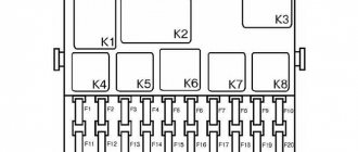
Fuse box in Volkswagen Golf 2
The Golf 2 has special blocks for fuses and relays. The arrangement of elements in these blocks is determined by a number of rules that must be followed.
Characteristic
The machine uses blade fuses. The color of each element corresponds to a specific protection current. Determine the part to be repaired by checking the wire guide between the contacts. If the thread is in place, it means it is functional. A burnt wire indicates a malfunction.
Some electrical circuits do not have fuses. Their function is performed by thermal relays, which can turn on automatically after the overload is eliminated. The exact location and pinout of the fuses in the Golf 2 can be seen below.
Location
The location of the unit depends on the year of manufacture of the car and its equipment.
- In most cases, the main fuse box for Volkswagen Golf 2 is located in the engine compartment on the right side. Next to the partition you can see 24 fuses and about the same number of relays. The exact number of relays may vary depending on the connected equipment. The Volkswagen Golf 2 fuse diagram is located on the back of the block cover.
- There is also an additional lock in the cabin, which can be accessed by opening the glove compartment.
- The radio fuse is located separately. Installed on the receiver power cable under the front panel next to the heating element.
The easiest way to determine the location of fuses in Golf 2 is to use the instructions in Russian. The corresponding manual contains all the necessary information on these items, indicating the exact purpose.
- https://lib-auto.ru/zamena-zapchastej/predohraniteli-volkswagen-jetta-vi-shema-raspolozhenie-blokov.html
- https://VmyatinkaSam.ru/elektrika/blok-predohranitelej-dzhetta-5.html
- https://rti-bsk.ru/elektrika/folksvagen-dzhetta-predohraniteli.html
- https://uazlyuks.ru/komplektuyushhie/predohraniteli/predohraniteli-volkswagen-jetta-5/
- https://vsepredohraniteli.ru/volkswagen/jetta-6.html
- https://volt-bikes.ru/populyarnye-stati/blok-predohranitelej-i-rele-volkswagen-jetta-6.html
- https://vsepredohraniteli.ru/volkswagen/golf5-jetta5.html
- https://garrett-ace.ru/transmissiya/shema-predohranitelej-dzhetta-5.html
- https://kkkkk.ru/predohraniteli-dzetta-6/
- https://AvtoMonitor.ru/predohraniteli-vw-jetta-6.html
- https://zapchasti.expert/predoxraniteli/predoxraniteli-volkswagen-jetta-6.html
- https://new-kodiaq.ru/turbonadduv/shema-predohranitelej-jetta-6.html
- https://AutoLions.ru/remont/predohranitel-omyvatelya-polo-sedan-2.html
- https://akppzapchast.ru/predohranitel-omyvatelya-far-jetta-6/
- https://AvtoMonitor.ru/predohraniteli-vw-jetta-5.html
- https://MotorList.ru/dvigateli/predohraniteli-dzhetta.html
- https://aforizmus.ru/predohraniteli-dzetta-6/
- https://kuzov63.ru/nesushchaya-sistema/predohraniteli-folksvagen-dzhetta-5.html
- https://AccBook.ru/to-avto/predohraniteli-dzhetta.html
In the engine compartment
1) To access the fuses and the relay-mounting block located in the engine compartment, open the hood.2) Slide the cover fastening latches forward...3) and remove the cover.
Fuses and relays in the mounting block located in the engine compartment
Assignment of fuses/relays in the engine compartment mounting block
| Number | Current, A | Protected circuit |
| 1 | 30 | Front and right rear turn signal lamps, right brake lamp, front and right rear parking lamps, right reversing lamp, right low and high beam lamps, right fog lamp |
| 2 | 15 | Sound signal |
| 3 | 40 | Air pump |
| 4 | Reserve | |
| 5 | 50 | Main fuse |
| 6 | 50 | Ignition switch power circuit unloading relay |
| 7 | Reserve | |
| 8 | 30 | Windshield wiper motor |
| 9 | Right tail light lamp | |
| 10 | 15 | Oxygen concentration sensor |
| 11 | 5 | Brake light switch |
| 12 | 5 | Intake geometry variable valve |
| 13 | 10 | Air pump relay, power supply injector |
| 14 | 30 | Windshield wiper motor |
| 15 | 30 | Mechatronic unit for robotic gearbox |
| 16 | 5 | Interior equipment control unit |
| 17 | 20 | ABS control unit |
| 18 | 15 | Mechatronic unit for robotic gearbox |
| 19 | 5 | Instrument cluster |
| 20 | 40 | Ignition switch positive terminal relay |
| 21 | 15 | Audio head unit |
| 22 | 40 | ABS control unit, electric module pump |
| 23 | 30 | Front and left rear turn signal lamps, left brake lamp, front and left rear parking lamps, left reversing lamp, left low and high beam lamps, left fog lamp |
| 24 | Reserve | |
| 25 | 5 | Diagnostic connector |
| 26 | 15 | ECU |
| 27 | 20 | Fuel pump, ignition coil |
| 28 | 10 | Control oxygen concentration sensor |
| 29 | 5 | Telephone communication device (optional) |
| 30 | 10 | ECU |
| R1 | Air pump relay | |
| R2 | ECU power relay |
What to do when the cigarette lighter does not work
As already stated at the beginning, the most likely reason for a cigarette lighter failure is a blown fuse. Therefore, we take out the manual for your car, look for the fuse diagram and find the one that is responsible for powering the cigarette lighter socket. It can be either separate or combined with other systems (often it is marked in the form of a cigarette or the inscription Cigar).
“Ring” the desired fuse with a multimeter or test lamp to see if it is working. If there is no device, and the fuse itself does not have obvious signs of burnout, try replacing it with a similar one and checking the cigarette lighter. If it works, change the fuse. No - we are looking further.
Ringing cigarette lighter contacts using a multimeter
The second place that is quite easy to check is the cigarette lighter socket. Carefully inspect it for foreign objects or burn marks on the sides. Further actions will require disassembling the panel and removing the cigarette lighter socket, as well as the presence of a multimeter or at least a test lamp. Don't forget to first remove the negative terminal of the battery!
Disconnect the chip with the cigarette lighter connector from the body and ring the contacts (if necessary, turn on the ignition). If voltage is present, carefully inspect the housing. There may be plaque or oxide on the terminals and connectors of the cigarette lighter, which can be removed with a cotton swab dipped in alcohol (wait for it to evaporate before turning on the device). If this does not help and the socket is clearly burnt out, then only replacing it will help.
The next element that needs to be carefully inspected is the fuse on the cigarette lighter housing. Most often, it has a 90-degree curved shape and connects the cigarette lighter contacts. If it burns out, the problem can be solved using a soldering iron or replacing the housing. In most cases, it is enough to solder or screw a piece of wire (aluminum with a cross-section of 1.5 mm2), which will close the contacts and act as a fuse.
If, when the fuse is working, the “ringing” of the chip with connectors indicates a lack of voltage in the network, then the problem is either in the wires or in the fuse mounting block, in which the conductive paths burn out. Moreover, in domestic cars it is most likely tracks, and in foreign cars it is wires.
To finally verify this, you can go in two ways:
- Disassemble the mounting block and inspect it for damaged tracks. Don't forget to take pictures of how it was originally. If the tracks are damaged, they need to be soldered.
- Find the electrical diagram of the car, find the connectors that come out of the mounting block to the cigarette lighter and ring them. If the voltage goes out and the cigarette lighter does not work, you will have to change the wire, which is quite difficult. If there is no voltage, the problem is in the mounting block.
What to do if the cigarette lighter on VAZ cars does not work?
Since the cigarette lighter socket most often refuses to work for owners of domestic cars, below are some useful tips specifically for VAZs.
Start by inspecting the fuse. It is located in the mounting block in the engine compartment - the exact location can be seen in the diagram of your model:
- VAZ-2104, 2105, 2107 - F6 (8A/10A)
- VAZ-2115, 2114, 2108, 2109, 21099 - F7 (30A) or F4 (20A)
- VAZ-2101-2103 and 2106 - F1 (16A) and the entire 110 family - F6 (15A)
- Lada Kalina and Granta - F20 (15A)
- Lada Priora - F13 (15A), Lada 4x4 - F14 (16A)
- Vesta - F41 (20A)
- Largus - F19 (10A), F20 (7.5A) and F38 (15A)
- Xray (XRAY) – F33 (15A)
Ringing the cigarette lighter fuse using a homemade tester on a VAZ 2107
To determine if the cigarette lighter is faulty on a VAZ, ring the block (black - minus, red - power supply plus, white - plus when the lights are on)
If the fuse is working, also check if there is voltage in its socket.
The next step is to check if there is power at the cigarette lighter terminals. If your cigarette lighter only works when the ignition is on, turn the key in the lock. When the multimeter does not show 12 volts, then the problem is most likely in the tracks of the mounting block. Disassemble it and solder the burnt tracks. Well, if the multimeter shows that there is power, you need to change the cigarette lighter housing itself.