When switching to the first position from zero, voltage is supplied to the 30th and 15th contacts. This is how the elements from the list are made available (not included):
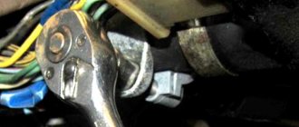
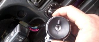
For the “fourteen” model range, VAZ designers chose the right-hand location of the lock. This option distinguishes the model range from the first “classic” cars of the plant. In this case, the switching zone remains under the steering column. The working part is hidden by plastic decor, so only the end of the cylinder is accessible to the driver.
This unit consists of several components. The main ones are the following components:
- durable metal case;
- unique locking mechanism;
- locking block;
- electrical part in the form of a contact group.
The presence of a steel case is designed to protect against unauthorized access to internal components. The locking mechanism borrows its characteristics from a conventional door lock with a “secret”.
Thanks to the built-in locking mechanism, it is possible to fix the steering wheel, preventing it from turning, with a free “secret”. The contact group is connected from the back and is responsible for the timely connection of contacts at a certain position of the key in the keyhole.
Unscrewing the ignition switch bolts with a chisel In practice, replacing the ignition switch on a VAZ 2114 will be impossible until you get rid of the old one. This is not difficult to do, but you will have to spend some time on your car.
VAZ starter connection diagram
VAZ cars use starters, which are a DC electric motor with an electromagnetic two-winding traction relay and a roller freewheel clutch (overrunning clutch). Starters are used to provide the minimum crankshaft speed required to start the engine. The starter is powered in starting mode from the battery.
The starter relay is connected to the power circuit, thereby closing and opening the circuit, depending on how fast the crankshaft rotates. The starter design on all cars is the same, with only minor design differences. If you understand how the starter works in one car, you can easily figure it out in another.
To prevent a starter failure from taking you by surprise, let’s look at how to replace it yourself. But first, read the theory and study all the options for starter connection diagrams for different models of VAZ cars, collected by the editors of 2 Schemes.ru from familiar auto electricians.
VAZ 2101 starter connection diagram
- starter;
- holding winding of traction relay;
- ignition switch;
- generator VAZ 2101;
- fuse box;
- pull-in winding of the traction relay;
- accumulator battery.
Under normal loads, the current generated by the starter is 150 A. When heavy loads occur, for example in winter, the resulting current can reach 500 A. This is a serious test for this electrical unit, so it is not recommended to keep the key on the start for more than 10 seconds, and repeated starting attempts must be made with a break of at least a minute.
VAZ 2106 starter connection diagram
- starter;
- generator;
- accumulator battery;
- pull-in winding of the traction relay;
- ignition switch;
- traction relay holding coil
| 1 – drive side cover; | 14 – relay cover; |
| 2 – retaining ring; | 15 – contact bolts; |
| 3 – restrictive ring; | 16 – collector; |
| 4 – drive gear; | 17 – brush; |
| 5 – overrunning clutch; | 18 – armature shaft bushing; |
| 6 – drive ring; | 19 – cover from the collector side; |
| 7 – rubber plug; | 20 – casing; |
| 8 – drive lever; | 21 – shunt coil of the stator winding; |
| 9 – relay anchor 2106; | 22 – body; |
| 10 – holding winding of the traction relay; | 23 – stator pole fastening screw; |
| 11 – pull-in winding of the traction relay; | 24 – anchor; |
| 12 – relay coupling bolt; | 25 – armature winding; |
| 13 – contact plate; | 26 – intermediate ring. |
Starter diagram VAZ 2108, 2109, 21099
Electric current enters the starter circuit from terminal “30” of the generator. Next, through block Ш8 (Х8) of the mounting block (pins 5,6), block Ш1 (Х1) - pink wire, to the ignition switch. The driver turns the key in the ignition to turn on the starter (position 2) and closes the contacts (50, 30). After which the ignition switch, through the red wire, current flows to block Ш1 (X1) of the mounting block (pin 8), then block Ш5 (Х5) (pin 4), starter switch relay (pin 85). The relay is activated. From terminal “30” of the start relay, current flows to terminal “50” of the starter traction relay, energizing its winding. The traction relay is activated, activating the starter.
The starter electrical circuit uses a switching relay 111.3747-10.
- Screw securing the protective cap.
- Protective cap.
- Retaining half ring.
- Rear cover fastening nut.
- Back cover.
- Brush springs.
- Brush guides (outer part).
- Brushes.
- Stator.
- Anchor.
- Drive lever.
- Drive unit.
- Restriction ring.
- Retaining ring.
- Drive lever axis.
- Screws for securing the traction relay.
- Front cover.
- Plastic sealing ring for the lid.
- Tie rods.
- Rubber plug.
- Traction relay core.
- Return spring.
- O-ring for traction relay.
- Traction relay.
- Sealing washer.
- Adjusting washers.
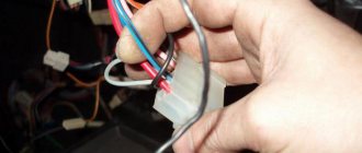
Wires of the ignition switch of a VAZ 2114 (2113, 2115) car
A block with wires of different colors is attached to the ignition switch (ignition switch) of the VAZ 2114 (2113, 2115) car.
Let's try to figure out which wire goes to what and which electrical circuits the ignition switch closes when the key is turned to different positions.
Wires of the ignition switch of a VAZ 2114 (2113, 2114) car
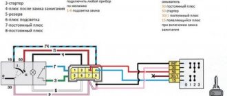
What electrical circuits are closed when the key is turned in the ignition switch of a VAZ 2114
Key position "0" - off
Contact “30” of the ignition switch is energized (terminal “7” of the lock wire block). Nothing is turned on (does not close).
Position "I" - ignition
The lock contacts “30” and “15” are closed (terminals “7” and “4” of the block).
Voltage is supplied to the following consumers.
— Electronic engine control unit (ECM) — Generator field winding — Turn signals — Control instruments — Windshield wiper and washer — Heater motor — Heated rear window — Cigarette lighter
Key position "II" - starter
The lock contacts “30” and “15” are closed (terminals “7” and “4” of the block).
— Electronic engine control unit (ECM) — Generator field winding — Headlights — Turn signals — Control instruments — Windshield wiper and washer — Heater motor — Heated rear window — Cigarette lighter
The lock contacts “30” and “50” are closed (terminals “7” and “3” of the block).
Starter circuit for VAZ 2110, 2111, 2112
Starters of type 57.3708 were installed on VAZ-2110 cars and had the following technical characteristics:
- Rated power 1.55 kW
- Current consumption at maximum power no more than 375 Amperes
- Current consumption in the inhibited state is no more than 700 Amperes
- Current consumption in idle mode no more than 80 Amperes
The connection diagram for the starter for the ten is shown above, here is its explanation:
- battery
- generator
- the starter itself
- egnition lock
| 1 – drive shaft; | 20 – contact bolts; |
| 2 – front cover bushing; | 21 – output of “positive” brushes; |
| 3 – restrictive ring; | 22 – bracket; |
| 4 – gear with the inner ring of the overrunning clutch; | 23 – brush holder; |
| 5 – overrunning clutch roller; | 24 – “positive” brush; |
| 6 – drive shaft support with liner; | 25 – armature shaft; |
| 7 – planetary gear axis; | 26 – tie rod; |
| 8 – gasket; | 27 – back cover with bushing; |
| 9 – lever bracket; | 28 – collector; |
| 10 – drive lever; | 29 – body; |
| 11 – front cover; | 30 – permanent magnet; |
| 12 – relay anchor; | 31 – armature core; |
| 13 – holding winding; | 32 – armature shaft support with liner; |
| 14 – retractor winding; | 33 – planetary gear; |
| 15 – traction relay; | 34 – central (drive) gear; |
| 16 – traction relay rod; | 35 – carrier; |
| 17 – traction relay core; | 36 – gear with internal teeth; |
| 18 – contact plate; | 37 – layering ring; |
| 19 – traction relay cover; | 38 – hub with the outer ring of the overrunning clutch. |
Starter solenoid relay
The starter relay is called a pull-in relay. This is due to the principle of its operation - it performs the function of connecting the starting device to the electrical circuit and connecting its armature to the crankshaft. It happens like this: when no current is supplied to the windings of the device, its armature, under the action of the return spring, remains in the forward position. The same spring, through a special fork, holds the Bendix gear, preventing it from engaging with the crankshaft flywheel ring.
By turning the key in the ignition, we supply current to the winding of the device. Under the influence of an electromagnetic field, the armature is fed back (pulled into the housing), closing the starter power contacts. The Bendix gear also moves, engaging with the flywheel. At the same moment, the retracting winding is turned off, and the holding winding comes into play. The force from the starter shaft is transmitted through the gear to the flywheel, causing the crankshaft to rotate until we no longer hold the ignition key in the start position.
What functions does the solenoid relay perform:
- Protects the starter from shorting contacts in the ignition.
- In order to turn off the power to the starter in a situation where the engine is running and the key shows the “starter” mode.
- Provides relief of contacts in the ignition switch.
When the engine starts, voltage from the generator goes to the relay coil. Then the gears of the drive system begin to work, due to which a magnetic field is created. The flywheel of the propulsion system is working. The gear begins its work thanks to the holding winding, while the bolts are closed. When the key is returned to the ignition switch, the winding is de-energized, thus disconnecting the gear and flywheel. This scheme applies to modern cars, including VAZ models.
If the starter makes a loud noise, the pole or starter could be loose. In the first situation, strengthen the fastening by tightening the screw, and in the second, secure the starter. If you disassemble the starter and see that the clutch is starting to slip, then the only thing you need to do is replace the starter drive.
Steering lock testing
Steering wheel testing
If you don't check the steering lock, you may encounter certain problems in the future. Therefore, do not waste your time on this event. It consists of removing the key from the ignition and turning the steering wheel at a slight angle.
- If there is no lock, you will need to slightly adjust the position of the lock. Make sure it fits into the groove located on the steering shaft.
- If the locking is effective, you will only need to tighten the four installed breakaway bolts until they stop. Twist until the heads break.
When the lock installation is completed and the test has passed, do not forget to connect the device to power and start the engine. If it starts, all systems dependent on the ignition switch are working, you can fully begin reassembly. Follow the reverse instructions for removing the casing and steering column switches. It would not be amiss to check the condition of certain nodes along the way. It is quite possible that some of them also need replacement or a little preventive maintenance.
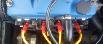
Connecting wires to the starter
Connecting a starter to a VAZ - instructions. Attach the relay in a convenient place (for example, a washer reservoir). Connect the wires to the starter. Then remove the red wire located on the flat terminal of the relay, and you need to make a connection with the connector of the male wire and the wire from the new relay.
Place the wire with a ring terminal for 8 mm on the positive side of the starter and tighten it with a nut. Place the wire of the new “female” type relay onto the contact that was released at the traction relay. This wire will transmit the positive to the coil. Using a clamp, tighten the new wire and the stock one together. Screw a small length of wire from the coil. Now you can turn on the new relay.
Source
VAZ ignition switch pinout
The ignition switch in cars of the VAZ family fails from time to time due to weakening of the contact posts or burning of the contacts inside it. It also happens that the cams of a plastic roller are produced. You can disassemble the lock and clean it, but it’s better to just replace it with a new one, considering that it costs pennies compared to imported locks.
But if connecting the wires together did not result in the starter operating (or it did not turn on the first time), check the solenoid relay on the starter. The contact spots on it may also burn out, which will prevent the circuit from closing normally. Alternatively, you can use a screwdriver to short-circuit the two large terminals on the solenoid relay (before doing this, put the car in neutral and use the handbrake). When closed, the starter should begin to spin vigorously. If this happens, remove and change the solenoid relay. If the starter rotates “sluggishly” when it closes, you will have to remove it and check the condition of the brushes.
All operations are performed with your own hands, without the help of car service specialists. Moreover, the price of an ignition switch on a VAZ2106 is up to 100 rubles. To replace it, you will need to know the pinout of the wires coming from it, for which the editors of the site 2 Schemes.ru have prepared a large reference material.
The ignition switch is designed not only to start the engine - it performs several functions at once:
- supplies voltage to the vehicle’s on-board network, closing the circuits of the ignition system, lighting, sound alarm, additional devices and instruments;
- at the driver’s command, turns on the starter to start the power plant and turns it off;
- turns off the power to the on-board circuit, preserving the battery charge;
- protects the car from theft by fixing the steering shaft.
Preparation
At the preparation stage, you will need to collect the necessary tools near you, which will be useful in the process of dismantling and installing a new ignition switch. You will also have to remove the steering cover and steering column shifters. Doing this is quite difficult, but we will tell you step by step about all the nuances of these preparatory activities. So you can easily figure out for yourself how to remove the ignition switch on a VAZ 2114.
Article on the topic: Self-repair of struts on a VAZ 2109 (Video) Replacement process The tools you will need:
- Phillips strong screwdriver;
- Open-end wrench 10 millimeters;
- Chisel;
- Hammer;
- Pliers or pliers;
- New ignition switch assembly;
- Lock mounting screws (4 pieces).
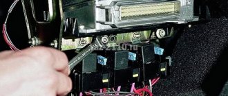
Now let's move on to the casing and switches. For more convenient work, many advise removing the steering column switches and the steering wheel itself. Dismantling the casing is performed in the following sequence:
- Disconnect the negative cable from the battery. Nobody has yet canceled the requirements for personal safety and protection against electric shocks;
- Unscrew the three screws securing the two parts of the casing. A screwdriver is useful for this;
- Unscrew the screw that connects the housing to the connector of the steering column switches;
- Remove the two screws that hold the lower housing to the steering column;
- The lever that fixes the column at the corner leads down;
- The steering wheel also goes down;
- The lower casing is then removed;
- The power supply from the emergency lights must be disconnected;
- Now you can remove the top casing;
- To dismantle the steering column switches, you need to act one by one;
- Simultaneously press both latches and thereby remove the elements from their seats;
- Disconnect them from the power supply.
Removing the ignition switch
Pinout of the ignition switch VAZ-2101 - VAZ-2107
The ignition switch on these cars is located to the left of the steering column. It is fixed directly to it using two fixing bolts. The entire mechanism of the device, except for the upper part in which the keyhole is located, is hidden by a plastic casing.
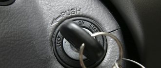
On the visible part of the ignition switch housing, special marks are applied in a certain order, allowing inexperienced drivers to navigate the lock activation mode when the key is in the hole:
- “ ” – a mark indicating that all systems, devices and instruments that are turned on using the lock are turned off (this does not include the cigarette lighter, interior lighting, brake light, and in some cases the radio);
- “ I ” is a mark informing that the vehicle’s on-board network is powered from the battery. In this position, the key is fixed independently, and electricity is supplied to the ignition system, to the electric motors of the heater and windshield washer, instrumentation, headlights and light signaling;
- “ II ” – engine start mark. It indicates that voltage is applied to the starter. The key does not lock in this position. If you release it, it will return to the "I" position. This is done so as not to subject the starter to unnecessary loads;
- “ III ” – parking mark. If you remove the key from the ignition in this position, the steering column will be locked with a latch. It can only be unlocked by inserting the key back and turning it to position “0” or “I”.
The ignition switch has five contacts and, accordingly, five terminals, which are responsible for supplying voltage to the desired unit. All of them are numbered for convenience. Each pin corresponds to a wire of a certain color:
- “50” – output responsible for supplying current to the starter (red or purple wire);
- “15” – terminal through which voltage is supplied to the ignition system, to the electric motors of the heater, washer, and instrument panel (double blue wire with a black stripe);
- “30” and “30/1” – constant “plus” (pink and brown wires, respectively);
- “INT” – external lighting and light signaling (double black wire).
How to check the ignition switch?
Breakdowns can be external and internal. External ones include loss or defect of the key, as well as visible damage to the lock itself. Sometimes you can see a piece of debris stuck in it. It is also worth checking the reliability of the connection of the block. Perhaps the wires simply came loose. Internal defects are associated with failure of the part itself or its electrical wiring. To determine such a malfunction, you will need a multimeter.
Diagnostics is carried out according to the following algorithm:
- Set the measuring device to ohmmeter mode;
- Remove the steering column cover;
- Disconnect the block with wires;
- Inspect the connector and find pins 7 and 4 on it;
- Connect the multimeter probes to them;
- Set the key to the “Ignition” position;
- Connect the ohmmeter probes to pins 7 and 3, then turn the key in the lock to the “Engine Start” mode.
If the lock is working properly, then during measurements the multimeter will show no resistance. If it is, it means the part has failed. It is usually beyond repair. Therefore, replacement will be required.
Checking with a multimeter will allow you to accurately determine the faulty element. In case of visual damage or loss of the key, replacement of the part is required. If self-diagnosis does not help identify the problem, you should consult an auto electrician.
Pinout of lock VAZ-2108, VAZ-2109, VAZ-21099
Pinout according to the old type
Pinout of the VAZ-2109 ignition switch with unloading relay:
- comes +12V in position I, II, III (parking)
- comes +12V in position I, II, III (parking)
- comes +12V in position III (parking)
- position I, +12V goes out after turning on the ignition (contact 15/2), disappears at start (II);
- position I, +12V goes to the starter (pin 50);
- position I, +12V goes away after turning on the ignition (pin 15), does not disappear when starting II;
- +12V comes from the battery (pin 30);
- comes +12V constantly.
New pinout type
Pinout of the new VAZ-2109 ignition switch:
- comes +12V constantly
- comes +12V constantly
- +12V arrives after turning on the ignition (pin 15), does not disappear when starting II;
- +12V arrives after turning on the ignition (contact 15/2), disappears at start (II);
- position I, +12V goes to the starter (pin 50);
- +12V arrives after turning on the ignition (pin 15), does not disappear when starting II;
- +12V comes from the battery (pin 30);
- comes +12V constantly.
Second nuance
If you do not have new ignition switch mounting bolts, it is very difficult to find them in stores.
The ignition switch should be screwed with this bolt, turn it with the key until the upper head breaks off
I couldn’t tighten the old ones to the required force, I don’t even know why they came up with such a design from the factory, maybe someone knows, please write. I didn’t look for new bolts, I just sawed off the heads so that a screwdriver would fit.
We clamp the bolt in a vice and file it, trying on a screwdriver
Pinout of lock VAZ-2110, VAZ-2111, VAZ-2112
Pinout of the ignition switch VAZ-2110:
- comes +12V for the microphone of the sensor of the inserted key;
- the mass comes when the driver's door is open;
- +12V goes to the starter (pin 50);
- +12V goes out after turning on the ignition (pin 15);
- +12V goes out when the key is inserted to pin 5 of the BSK;
- comes +12V to illuminate the lock cylinder;
- +12V comes from the battery (pin 30);
- not used.
Pinout of lock VAZ-2113, VAZ-2114, VAZ-2115
Pinout of the ignition switch VAZ-2113, 2114, 2115:
- comes +12V for the microphone of the sensor of the inserted key;
- the mass comes when the driver's door is open;
- +12V goes to the starter (pin 50);
- +12V goes out after turning on the ignition (pin 15);
- +12V goes out when the key is inserted to pin 5 of the BSK;
- comes +12V to illuminate the lock cylinder;
- +12V comes from the battery (pin 30);
- not used.
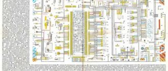
Wiring diagram for the ignition switch on a VAZ 2114
The ignition switch pinout is necessary to install the part or identify the cause of the malfunction. The VAZ 2114 ignition switch will be connected to the on-board network according to the following principle:
This is a general diagram of the “four” electrical equipment. You can download it in good quality from the link below.
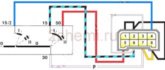
And what the VAZ 2114 ignition switch block is connected to is clearly shown in the figure with a description of the contact connections:
To understand which wires from the block go where, there is the following pinout of wires, shown in the figure:
Thus, it is not difficult to figure out how to connect this part to the vehicle’s on-board network.
The structure of a car ignition switch
- Locking rod
- Frame
- Roller
- Contact disc
- Contact sleeve
- Block
- Protrusion of the contact part.
The lock mechanism is connected to many wires. They continue from the battery, connecting all the electrical devices of the car into a single chain. When you turn the ignition key, the electrical circuit is closed from the “-” terminal of the battery to the ignition coil. As a result, the current passes through the wires to the ignition switch, through its contacts it is directed to the induction coil, after which it returns back to the “+” terminal. As electricity passes through the coil, it generates high voltage, which it transmits to the spark plug. Therefore, the key closes the contacts of the ignition circuit, thereby starting the car engine.
Electrical fault
The primary reason for the failure of the contact group is overloading the electrical equipment of the car.
Thus, installing additional lighting devices and power-consuming devices may lead to the lock not being able to withstand the load. Due to the large load for which the contact group is not designed, carbon deposits appear, which form inside the metal, and not outside.
Disassembling the ignition switch to troubleshoot
To avoid overloading the ignition switch, all additional devices must be connected through a relay, which will relieve part of the load. As practice shows, this particular solution to the problem becomes optimal.
Of course, another reason that can cause the ignition switch to fail is a short circuit, which occurs quite often in Ladas.