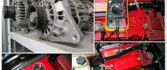
To successfully monitor the state of charge of the battery, it is important to know how to connect a voltmeter in the car and how to decipher its readings. Since the advent of cars equipped with an on-board computer, the need for a separate voltmeter has faded into the background, because it does not provide complete monitoring of all electrical components of the car. The relevance of the device is also determined by the need to constantly monitor the battery charge, which is especially important in winter. In the event of a sharp drop in voltmeter readings, it becomes possible to take appropriate countermeasures and avoid unexpected engine shutdown.
A voltmeter is a useful device for cars that do not have an on-board computer. Using it you can monitor the battery charge status.
Installing a voltmeter in a car
A voltmeter in a car is a rather rare feature. This probably happens because the average motorist is unlikely to often think about voltage, which cannot be said about those who like to keep everything under control... Installing a voltmeter in the car yourself will help you always be aware of the “volts”!
Which voltmeter to choose?
It is extremely difficult to find a car voltmeter, and even a decent looking one, in stores. This happens because such equipment is installed from the factory in literally single cars. If we discard the tuned instruments, then in reality you can only find voltmeters from the VAZ-2107 and UAZ.
The voltmeter from the VAZ “Seven” does not have a housing and this is a huge minus. According to the “statement”, it is attached to the dashboard and “naked” consists of unprotected windings on a small frame and an arrow made of soft metal...
The UAZ voltmeter is a full-fledged device in a sturdy case. The only real negative is the appearance. It is, as befits this car, extremely unpretentious, even military.
The design and quality of the voltmeters considered are unlikely to be suitable for beautiful tuning. Therefore, for those who not only add functionality to their car, but also take into account the interior design of the car, it is better to look for a specialized tuned device.
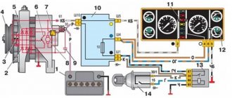
Connecting a voltmeter to a car
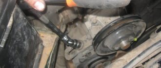
Ideally, the voltmeter should be connected to the positive terminal of the battery - then it will show the most accurate charging voltage. It is required to conduct a wire from the terminal into the interior to the place where the device will be installed. Before starting work, you need to disconnect the battery, take a wire with a cross-section of about 0.5 mm and stretch it into the cabin along the standard wiring harness. It is quite possible that for this you will have to disassemble some of the casing and run wires under the dashboard.
The voltmeter should only work when the ignition is on. When connected directly to the battery terminal, it will be constantly on. You can get around this problem using a conventional electromechanical relay, which is used in abundance in any car.
You can read in detail about how a relay works in a car and how to connect through a relay by following the links. Installing a voltmeter in a car follows the same scheme, namely:
– The wire going from the battery to the device is “power” in this case. A relay is installed in its gap, which, when turned off, opens this wire, turning off the voltmeter.
– We take the voltage to the “positive” control contact of the relay from the place where it appears when the ignition is turned on. It could be anything - a mounting block, ignition switch wires, and so on.
– We connect the “minus” of the voltmeter and the second control contact of the relay to “ground”, that is, we screw it to the body with a standard “bolt” terminal.
Now, when you turn on the ignition, the installed relay will operate, connect the voltmeter, and it, in turn, will show the number of volts in the on-board network.
Voltmeter protection and backlight
At this point, installing a voltmeter in a car may be completed, but ideally two more steps need to be performed - one for safety, and the second for comfort.
To protect the voltmeter's power circuit from a short circuit, it is necessary to install a fuse on the wire coming from the battery. This is very simple to do, just cut this wire in a suitable place, crimp two female terminals on it and put them on the terminals of the fuse. Its rating should be small, for example, 5A (More details about fuse ratings are here). It is better to wrap the terminals, and for reliability, the fuse itself, with electrical tape.
And finally, the final step is to illuminate the voltmeter. All devices that are placed in the housing must have it. It is necessary to extend the wire to the backlight contact from where the voltage appears when the side lights are turned on. The “minus” of the backlight, as a rule, is combined with the common negative terminal of the device, and in our case it is already connected to the car body.
Thus, by running just one additional wire, we will get not only a working voltmeter, but also illumination of its scale.
PS You need to connect a voltmeter to the battery terminal so that it shows the most accurate voltage. If special accuracy is not required, you can connect the device to any wire in the car interior, on which voltage appears when the ignition is turned on. This is much simpler and faster, does not require the installation of a relay and fuse, since the electrical circuit is protected by default.
With this connection, the voltmeter readings will be slightly lower than in the method discussed in detail above, because on the way from the battery to the passenger compartment, the voltage may decrease due to the large number of different contacts and the resistance on them.
You can download convenient instructions for connecting a voltmeter on an A4 sheet. Print it out and take it with you. File size 1.5 MB, jpg format.
Source
Pinout of the dashboard of VAZ2105, 2106, 2107
Old panel (with oil pressure gauge)
In addition to the presence of an oil pressure indicator, it is worth noting that this instrument panel does not have an air damper indicator lamp (choke), and the emergency oil pressure lamp is located next to the pressure indicator. Because of this, it contains lamps for low brake fluid levels and fog lamps.
White 6-terminal block X1:
- Gasoline level sensor
- Turn signal indicator lamp
- Battery charge sensor (voltmeter -)
- Gasoline level warning lamp
- Overall plus (+)
- Battery charge sensor (voltmeter +)
White 8 terminal block X2:
- Fog lamp warning lamp
- High beam warning lamp
- Dimensions indicator lamp
- Empty
- Battery charge indicator lamp
- Brake fluid level warning lamp
- Empty
- Parking brake warning lamp
Orange 6-terminal block X3:
- General minus (-)
- Tachometer VAZ
- Instrument lighting
- Oil pressure sensor
- Oil pressure warning lamp
- Coolant temperature sensor
New instrument panel (with econometer)
Here, everything is the other way around - there is no oil pressure indicator (instead there is an econometer), instead of a brake fluid level lamp there is a suction lamp (or an engine management system lamp on injectors), and instead of a fog lamp lamp there is an oil pressure lamp.
White 6-terminal block X1:
- Gasoline level sensor
- Turn signal indicator lamp
- Battery charge sensor (voltmeter -)
- Gasoline level warning lamp
- Overall plus (+)
- Battery charge sensor (voltmeter +)
White 8 terminal block X2:
- Dimensions indicator lamp
- High beam warning lamp
- Oil pressure warning lamp
- Empty, but there is a terminal in the wiring that goes to the brake fluid level sensor
- Battery charge indicator lamp
- Indicator lamp for the air damper (choke) or engine control unit for injectors
- Empty
- Parking brake warning lamp (handbrake)
Orange 6-terminal block X3:
- General minus (-)
- Tachometer (if this contact is empty, then the tachometer is on pin #4)
- Instrument lighting
- Empty, and if not empty - to the tachometer
- Empty
- Coolant temperature sensor
Second connection diagram option
How to properly connect a voltmeter to a car
Drivers of cars and trucks are interested in how to connect an ammeter and voltmeter in a car.
The need to install these indicators is explained by the desire to have full control over the condition of the battery and generator set. Most modern cars and previously produced ones do not have such indicators installed by the manufacturer. True, in cars with on-board computers, it is possible to control the voltage in the car’s circuits; in other models, the owners install the devices. How to connect an ammeter and voltmeter in a car is especially interesting for owners of used cars, since many components and assemblies, including the generator set, are already quite worn out, so they may not work properly. The warning lamp only signals the absence of on-board voltage, and this is clearly not enough. For example, if you do not notice the increased charging voltage of the battery in time, this can lead to its failure.
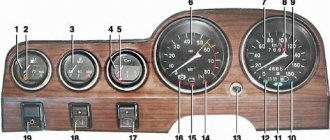
VAZ instrument panel indicators - explanation
- coolant temperature gauge.
- tachometer;
- left turn signal indicator lamp;
- right turn signal indicator lamp;
- speedometer;
- fuel level indicator;
- fuel reserve warning lamp;
- side light indicator lamp;
- service brake system warning lamp;
- high beam indicator lamp;
- reset button;
- mileage indicator;
- warning lamp for turning on the hazard warning lights;
- "check engine" warning light;
- time and temperature indicator;
- battery charge indicator lamp or battery lamp;
- parking brake warning lamp;
- oil pressure warning lamp;
- reserve.
VAZ dashboard indicators play an important role in informing the user about malfunctions. They help prevent errors in the system, so it is important to know which indicator means what. How does the panel work? If any problem occurs, the sensor immediately sends information to the panel, and the driver will see an orange signal light up.
The earlier version of the instrument panel had some other symbols, such as emergency oil pressure, handbrake engaged, Chek Engine light, and several others that indicate minor operating errors, but which are no longer used.
About the functions performed by these pointers
Each control or measuring device installed in the instrument panel of the car informs the driver about the performance of a certain vehicle system. This allows you to operate the machine without compromising its technical condition. However, the electrical supply system of many cars does not have the ability for such control. Car owners try to solve such problems on their own by installing an ammeter or a voltmeter, and some owners install both of these indicators.
An ammeter installed in an electrical circuit will indicate the electrical current consumed by the system. Using these data, you can judge the battery charging process and promptly identify and eliminate problems that arise. The voltmeter also allows you to keep this process under the control of the driver, which increases the service life of electrical equipment. Here are the main reasons for installing these devices on a car.
What products are used?
Some time ago, finding and installing such a device was a big problem. Motorists installed ammeters from trucks on their cars, and those drivers who were familiar with radio electronics selected the measuring instruments themselves. The first domestic cars in which the voltmeter took its permanent place on the instrument panel was the VAZ 2105, and a little later they appeared on other models.
Today such a problem does not exist, since there is a large selection of such products in retail chains. You can install an electronic clock in the panel, which simultaneously shows the voltage of the on-board network along with the current time. There are electronic tachometers, which, after pressing the desired button, perform the functions of a voltmeter. Such devices do not cause any particular problems for owners.
Also today, automobile ammeters and voltmeters are available for sale, and individual drivers independently adjust the devices that are used in radio-electronic devices. Installing such indicators is fraught with some difficulties, since it is necessary to select shunts for them, calibrate or manufacture new scales. Therefore, we will not dwell on this.
How to install such indicators?
Let's assume that you managed to purchase an ammeter or voltmeter intended for use in cars; now let's look at the process of installing them. It is worth recalling the features of connecting them to electrical circuits.
The ammeter is connected only in series between the current source and the consumers, and the polarity of the connection must be observed, plus from the source to the plus of the device, and so on. The voltmeter is connected only in parallel to the power source, also subject to polarity.
VAZ dashboard pinout
When repairing or replacing the dashboard (instrument panel) of VAZ cars with a more convenient and modern version of VDO, made with LEDs, you will need connection diagrams and pinouts of panel connectors. For this purpose, the editors of 2SHEMI.RU have prepared a complete collection of panel contact pinouts for all popular models of this car.
The main symbols that are found on the dashboard of absolutely any car of the VAZ family are: speedometer, fuel gauge, tachometer and sensors to indicate engine temperature.
Connecting the ammeter
Let's start with the fact that work can only begin after the battery is disconnected. Significant current flows through this device, so you need to select wires of the appropriate cross-section. It should be connected to the wire gap that supplies power to the ignition switch. Tips should be installed and crimped with pliers on the ends of the wires, otherwise the connection point will heat up due to poor contact.
After installing the wires, check that the connections are correct. To do this, turn on the load, for example, low or high beam. The ammeter should show a discharge; if it shows the opposite value, then the connection wires should be swapped. Next, you should start the engine and make sure that the battery is charging.
Pinout of the dashboard of VAZ2110, 2111, 2112
- fuel reserve warning lamp;
- dashboard lighting lamps;
- right repeater indicator lamp;
- left repeater indicator lamp;
- VAZ plug block;
- coolant temperature sensor;
- indicator lamp for external lighting;
- carburetor air damper warning lamp;
- oil pressure warning lamp;
- handbrake indicator lamp;
- battery charge indicator lamp;
- VAZ tachometer;
- indicator light “CHECK ENGINE”;
- speedometer dashboard;
- brake fluid level warning lamp;
- hazard warning lamp;
- high beam indicator lamp;
- fuel level indicator.
| White block (X1) | Red block (X2) | ||
| 1 | Housing (weight) | 1 | To terminal “W” of the fuel level indicator sensor |
| 2 | Tachometer (low voltage input from ECU) | 2 | Fuse F19 + 12V power supply |
| 3 | Tachometer (high voltage input from coil) | 3 | Housing (weight) |
| 4 | Const +12V from battery (via 6th fuse) | 4 | Instrument lighting switch |
| 5 | Coolant temperature sensor. | 5 | Turn signal RIGHT |
| 6 | Fuse F1 (side light) | 6 | Turn signal LEFT |
| 7 | Throttle valve (“choke”) | 7 | Brake fluid level |
| 8 | Check Engine Light | 8 | To the trip computer |
| 9 | Fuse F19 + 12V power supply | 9 | Speed sensor |
| 10 | Fuse F19 + 12V power supply | 10 | Terminal “T” fuel gauge |
| 11 | Parking brake, terminal “VK” | 11 | Fuse F3 (high beam) |
| 12 | Generator output “D” | 12 | Hazard switch |
| 13 | Oil pressure sensor | 13 | To terminal “50” of the ignition switch |
Turning on the voltmeter
Its connection is somewhat simpler, since it does not require selection of wire cross-section. The currents passing through it are insignificant and will not heat up. Just be sure to observe the polarity of its connection. You can also connect to the ignition switch or mounting block with fuses. Both indicators have a backlight, which is connected to the instrument panel lighting.
We hope that after reading this article, you will understand how to connect an ammeter and a voltmeter in a car. Our recommendations cannot be considered absolutely the same for all issued indexes, but they can be taken as a basis for the work performed. Some measuring instruments are supplied with detailed installation instructions, so there is nothing to be afraid of, proceed with installation.
Connection to the ignition switch
Modern digital voltmeters designed for installation on a motorcycle have a very small current consumption (usually no more than 20 mA). Therefore, they can be connected directly to the ignition switch contacts (without the risk of burning the contacts). Installation algorithm:
- we mount the measuring device in a place convenient for viewing (for example, using double-sided tape);
- We connect the black wire to ground (under any mounting screw);
- We find the +12V switched contact on the ignition switch and connect the red wire from the voltmeter to it.
The simplest option
Those who don’t want to bother with cutting plastic in the interior, wiring and other joys associated with a voltmeter can take the path of least effort. We are talking about exactly the same devices that work through the cigarette lighter. Yes, they have an error of about 0.1-0.2 V, but this is not so critical, and in the most famous Chinese store, you won’t have to pay more than 400 rubles.
Most of these options come with a built-in thermometer (takes data from inside the cabin), but this additional function is useless (you may not agree with us). However, if you search, you can find options where, in addition to voltage and temperature (or without it at all), there are 1-2 USB ports. But this is really convenient.
If you are interested in such options, write in the comments - we will compile a selection of trusted sellers.
Any motorcycle owner periodically has to check the voltage of the on-board network (usually using a multimeter). This must be done to control the operation of the generator and relay regulator; as well as the condition of the battery. If you make a simple tuning of your bike and install a voltmeter for the motorcycle, you can constantly receive information about the voltage of the on-board network. The variety of these devices (in terms of price, method of mounting and connection) allows such useful modifications to be made to the vehicle, even without having special technical skills or deep knowledge of electrical engineering.
Voltmeter in the cigarette lighter socket
For owners of motorcycles with a cigarette lighter socket (standard or installed independently), the easiest way to monitor the voltage of the on-board network is to install a ready-made measuring device specifically designed for installation in this socket. The choice is quite wide: there are highly specialized devices that display only voltage; There are devices equipped with an additional USB socket for charging mobile gadgets or a built-in thermometer.
The main advantage of such measuring instruments is their ease of installation, namely, just insert the device into the cigarette lighter and you can control the voltage of the on-board network.
No additional work (installation of a toggle switch, additional relay or fuse) is required. Disadvantage: quite often the cigarette lighter socket is initially installed in a poorly visible place.
Voltmeter with switch
Another simple and reliable way is to install a measuring device with a built-in switch. Installing such a voltmeter on a motorcycle is extremely simple:
Attention! After you have turned off the engine, be sure to turn off the voltmeter using the switch. During long-term parking, the device can drain the battery quite significantly.
Connecting a voltmeter via an additional relay
The most correct (from a technical point of view) way to connect a voltmeter for any motorcycle is to use an additional relay. For this method you will need:
The connection diagram is simple:
Now, when the ignition is turned on, the relay will be activated and the voltmeter will be connected to the battery through closed contacts (30 and 87).
To successfully monitor the state of charge of the battery, it is important to know how to connect a voltmeter in the car and how to decipher its readings. Since the advent of cars equipped with an on-board computer, the need for a separate voltmeter has faded into the background, because it does not provide complete monitoring of all electrical components of the car. The relevance of the device is also determined by the need to constantly monitor the battery charge, which is especially important in winter. In the event of a sharp drop in voltmeter readings, it becomes possible to take appropriate countermeasures and avoid unexpected engine shutdown.
Voltmeter is a useful device for cars that do not have an on-board computer. Using it you can monitor the battery charge status.
Connection diagrams and methods
The question often arises of how to connect an ammeter, in series or in parallel. Connecting the device in question into an electrical circuit break is not difficult. For safety reasons, this procedure is performed when the power source is turned off. You need to make sure in advance that the maximum current will not exceed the permissible values of the device. Such scales are duplicated in the accompanying technical documentation. When the supply voltage is applied, readings are taken. You need to wait until the needle stops oscillating. When it moves in the opposite direction, the polarity of the connection changes. If the current is too high, additional shunting is used.
The connection diagram of the device can be direct or indirect. In the first case, the device is directly connected to the electrical circuit between the power source and the load.
Before connecting the device, you must consider:
- direct or alternating current in the electrical network;
- Is the polarity of the device correct?
- the arrow of the device should be located beyond the middle of the scale;
- limits for measuring the maximum possible current surges in the circuit;
- whether the external environment meets the recommended indicators;
- Is the measurement location free from vibration?
Connecting the device
In DC circuit
Direct current can pass through different electrical circuits. As an example, we can cite all kinds of chargers and power supplies. To repair such devices, the technician must have an understanding of how the ammeter is connected to the electrical circuit.
At home, such skills will also not be superfluous. They help a person who is not too keen on radio electronics to determine for himself, for example, the time it takes to charge the battery from a camera.
To conduct the experiment, you will need a fully charged battery with a nominal voltage of, for example, 3.5 V. In addition, you need to use a lamp of the same rating to create a series circuit:
- battery;
- ammeter;
- bulb.
The entry that is marked on the measuring device is recorded. For example, a lighting fixture will consume 150 milliamps of electricity, and the battery has a capacity of 1500 milliamp-hours. Therefore, it will work for 10 hours, delivering a current of 150 mA.
Connecting to the charger
The question often arises of how to properly connect an ammeter to a charger. When using a charger, the need arises to measure the current. This will make it possible to control the process of accumulating electricity by the battery, and avoid overcharging and undercharging. As a result, the service life of the battery will increase significantly.
When operating a large number of technical devices, it becomes necessary to control the current strength. The ammeter needles or indicators on the monitor of a discrete device will show the operator such a physical parameter. The measurements taken are needed to maintain the operating condition and to signal the occurrence of an emergency.
We recommend reading: Radio panic button at home: step-by-step instructions
The principle of operation of a voltmeter in a car
A voltmeter is a device with a fairly simple internal structure, the main purpose of which is to measure the voltage in the network. The principle of operation of a voltmeter is the interaction between an electromagnetic coil and a permanent magnet or two electromagnets. The current passing through the coil deflects the voltmeter needle the more strongly, the higher the voltage value.
In modern devices, readings are converted into a digital display, which is clearly visible even at night in an unlit car interior. The accuracy of such sensors is much higher than analogue “pointer” models, and depends on the discreteness of the main component - the analog-to-digital converter. The input voltage, flowing through the wires, is converted into a digital signal, which is then converted from binary code to a numerical value and displayed on a backlit display.
History of invention
The Italian scientist Alessandro Volta, after conducting a series of experiments with electricity, comes to the conclusion that electric current can be obtained by combining metals with liquid.
By placing copper plates coated with zinc in acid, in 1800 he created the first electrochemical energy source, later called the “voltaic column”. He also establishes that when two different metals are joined, a force is generated, which is expended in the work of moving an electric charge from one point to another. In this case, the displaced charge changes its potential (the amount of energy) it possesses. The difference between the initial potential and the final potential is called “voltage”.
To measure the amount of electricity, Volt uses a metal rod inserted into a rubber stopper and placed in a bottle. He puts straws on the lower end, located in the bottle, and a ball on the other. The scientist observes that when the ball comes into contact with an electrified substance, the straws repel. This allows him to judge the degree of charge of the material.
Volt proved the existence of voltage by conducting the following experiment. A copper and zinc disk was placed on the electroscope (a device that records charge). A thin layer of dielectric is laid between them. For a short time, the physicist connected the metals together with a wire. The petals on the electroscope moved slightly apart. Next, the disks moved apart to a greater distance, while the recorder petals diverged even more.
In fact, this was the first experiment to measure, albeit in rough form, voltage. In 1830, the English scientist Michael Faraday discovered the phenomenon of electromagnetic induction, which was subsequently used to create a number of electrical measuring instruments.
In 1881, French physicist Arsene D'Arsonval created a device consisting of a coil and a pointer placed in a constant magnetic field. Electric current was supplied to the coil, causing the needle to deviate from its initial position. In the same year, the International Electrotechnical Congress was held, at which the designations of electrical quantities were adopted. The device designed to measure potential differences was called a voltmeter, and voltage began to be measured in volts.
Selecting a voltmeter model
Digital voltmeter circuit.
The modern market of devices for cars offers a wide selection of voltmeter models. The most popular types of devices are:
The last two types of devices are most often used, as they combine a modern appearance, accurate readings and ease of installation.
The measurement results that best correspond to reality are provided by voltmeters connected directly to the dashboard. Although their installation is sometimes fraught with some difficulties, by installing them you can get constant monitoring of the battery condition, which is especially important when there are a large number of connected components. Automotive voltmeter
The cost of a digital voltmeter is quite low and ranges from 120-150 rubles if ordered through online stores. It has a standard rectangular shape, thanks to which it will harmoniously fit into the interior of any car. Backlight color – white, yellow, blue, green, red. Sometimes a problem arises with the high brightness of the screen, which acts as a distraction and makes it difficult to concentrate on the road, but this problem can be quickly solved with the help of a tint film.
To increase the accuracy of the voltmeter, it is recommended to choose those models in which 4 digits are allocated for voltage readings. This way you can take values down to hundredths of a volt.
Installation specifics
Table of characteristics of a digital voltmeter.
If there are no problems during installation with digital voltmeters that are powered from the cigarette lighter, then models installed directly into the dashboard often force drivers to think about the order in which they are connected.
Most voltmeters on the market have two or three wires for connecting to the network, although there are models with four contacts. The wires have standard color markings:
In some cases, an unexpected problem arises when connecting the voltmeter in this way: it lights up dimly or refuses to work at all. The reason may be the alternative marking of the wires, in which the white wire is responsible for the “minus”, and the black wire for controlling the device.
The voltage sensor is installed in the standard place of the clock, but in some cases, when it is impossible to find free space for the voltmeter, you have to make a hole for it directly in the dashboard.
An excellent place to connect the device is the dashboard plug on the left side of the steering wheel. It is small in size and easy to remove and secure for processing.
Figure 1. Connection diagram for a voltmeter with a pulse stabilizer.
The voltmeter body has a raised surface: the frame around the display will protrude above the surface of the car panel. Thanks to this, the device will not fall inside the mounting socket, and will also hide uneven edges of the hole.
Inexpensive models of voltmeters may not have a separate wire for power; such a device is connected via three contacts on the sensor body (Fig. 1). In this case, the voltmeter is connected using a 4-wire wire from the computer drive (Fig. 2). The wide IDE format connector is cut off, and the remaining wiring is attached by soldering to the contacts of the car wiring. The 4-pin contact ensures a good connection and makes it possible, if necessary, to quickly and effortlessly replace the voltmeter if it breaks down.
Regardless of the structural features of the voltmeter, before installing it, the car’s wiring diagram is studied in detail, according to which the location of the device’s connection is determined. It would also be a good idea to carefully read the instructions for the device, since the methods for connecting it may differ.
Principle of operation
Electromechanical type meters were the first to be created. They operate using the magnetoelectric principle. A permanent magnet is fixedly fixed, and a steel core is installed between its poles. This structural element is installed in such a way that a constant electromagnetic field can be formed in the annular air gap.
A frame made of aluminum is installed in the gap on the axle shafts. She is able to move freely. There is also a spool of thin wire on the frame. The indicator arrow of the device is attached to the frame using springs. As soon as an electric current begins to pass through the device, an electromagnetic field appears in the winding. The frame interacts with it and deflects along with the arrow to a distance corresponding to the voltage value.
The design of the meter also contains an induction damper - an aluminum plate mounted on a frame with an arrow. In accordance with Lenz's rule, eddy currents arising in the damper interact with the magnetic field that generated them and slow down the oscillations of the device pointer. To achieve the required measurement accuracy, the device must not be exposed to gravity during operation.
To solve this problem, the moving part of the meter is equipped with a system of weights moving on rods. In addition, to ensure accurate measurements, it is necessary to reduce the friction force of the steel tips. This is achieved through the use of special wear-resistant steels. Parts made from them are polished.
Before starting the measurement, the user needs to set the indicator arrow to the zero position.
For this purpose, the design of the device includes a special adjustment screw connected to a spring. This is a classic design, but today there are devices containing magnets of different shapes. Moreover, in some designs the magnet is movable.
We recommend reading: Stabilizer AMS1117-3
Interpretation of instrument readings
Installing a voltmeter is only the first step in gaining control over the condition of the vehicle's battery and electrical system. Complete information can be obtained only by determining the basic values of the device indicators.
The standard battery voltage in passenger cars is 12 V. The on-board voltage readings will be slightly different, amounting to 13.7-14 V. If the values on the voltmeter decrease relative to the specified parameters, this may indicate a breakdown of the voltage regulator or a malfunction in the generator.
A decrease in voltage may also be due to the battery being discharged. This happens especially often in winter: in the cold, discharge occurs faster, and the presence of a heater in the car adds load to the network.
Figure 2. Diagram of connecting a voltmeter to a circuit.
If the voltmeter is connected directly to the battery terminals, then by its numerical values you can easily find out the battery charge level. Readings in the range of 12.6-12.9 V indicate that your battery is fully charged. As the discharge progresses, the voltage gradually drops. At a value of 12.3-12.6 V, the charge drops to 75%; at 12.1-12.3 V, the battery is approximately half discharged. With a gradual decrease in voltage to 11.8-12.1 V, the battery is considered 3/4 empty, and at 11.5-11.8 V you will no longer be able to start the car.
Pinout of the dashboard VAZ2108, 2109, 21099
Connection diagram of the instrument cluster before 1996.
1 – relay-interrupter for the parking brake warning lamp; 2 – tachometer with voltage stabilizer; 3 – instrument cluster lighting lamp; 4 – temperature indicator; 5 – BSK control unit; 6 – fuel level indicator; 7 – resistor 50 Ohm, 5 W; 8 – control lamp “CHECK ENGINE” for the toxicity reduction system; 9 – control lamp for high beam headlights; 10 – side light indicator lamp; 11 – backup warning lamp; 12 – warning lamp for unfastened seat belts; 13 – control lamp for left direction indicators; 14 – resistor 470 Ohm, 0.25 W; 15 – electronic voltmeter; 16 – control lamp for right direction indicators; 17 – warning lamp for emergency oil pressure; 18 – fuel reserve warning lamp; 19 – control lamp for the carburetor air damper; 20 – indicator lamp “CHECK ENGINE” for the fuel injection system; 21 – parking brake warning lamp.
Instrument cluster wiring diagram after 1996
1 – tachometer; 2 – instrument cluster lighting lamp; 3 – temperature indicator; 4 – BSK control unit; 5 – fuel level indicator; 6 – control lamp “CHECK ENGINE” for the toxicity reduction system; 7 – control lamp for high beam headlights; 8 – side light indicator lamp; 9 – backup warning lamp; 10 – warning lamp for unfastened seat belts; 11 – control lamp for left direction indicators; 12 – battery charge indicator lamp; 13 – control lamp for right direction indicators; 14 – warning lamp for emergency oil pressure; 15 – fuel reserve warning lamp; 16 – control lamp for the carburetor air damper; 17 – indicator lamp “CHECK ENGINE” for the fuel injection system; 18 – parking brake warning lamp; B1 – resistor 91 kOhm; B2 – resistor 50 Ohm, 5 W.