DMVR is a mass air flow sensor, or as it is popularly called, a flow meter. It is designed to regulate the flow of air through the throttle body to create the fuel mixture. If this sensor fails, more or less air may enter the cylinders, which will affect fuel consumption. The cleanliness of the throttle also affects the flow rate.
The video shows the symptoms of a faulty mass air flow sensor on a VAZ. A non-working mass air flow sensor was specially installed:
Checking the serviceability of the mass air flow sensor with a multimeter
You can also check the air flow in the VAZ-2110 using a multimeter.
This method is well suited if the car has a Bosch sensor with numbers 0280218004, 0280218037, 0280218116. Each cable in the VAZ-2110 sensor device provides separate functions:
- yellow – indicates the signal input to the installation;
- gray-white – removes supply voltage from the mechanism;
- green – determines the grounding output;
- pink with black - approaches the main relay.
Note that the wire colors may change, but the pinouts remain the same. For a better understanding of the mass air flow sensor in the VAZ-2110, a diagram of the sensor is presented below.
Step-by-step instructions for checking the mass air flow sensor in a VAZ-2110 with a multimeter look like this:
- Turn on the ignition, but do not start the engine.
- Connect the multimeter with the red wire to the yellow, black to green, using a probe. This procedure allows you to determine the voltage that has arisen between the terminals.
- What’s good about the probe is that it is inserted through rubber seals along the wires without violating the integrity of the insulating material. The use of needles is considered incorrect; the error in measurements may be large.
- Next, take readings from the multimeter.
The output voltage of the new device varies from 0.996 to 1.01 Volts. During operation, the values may change, mostly increasing. A higher voltage indicator indicates a greater degree of wear on the mass air flow sensor:
- from 1.01 to 1.02 – the sensor is fully operational;
- from 1.02 to 1.03 – the condition is not bad;
- from 1.04 to 1.04 - soon the air meter will have to be changed;
- from 1.04 to 1.05 – the condition is critical, operation is possible if no negative symptoms are reported;
- more than 1.05 – it’s time to replace the sensor on the VAZ-2110 immediately.
Checking the regulator for functionality
There are several options for diagnosing the device.
To check the mass air flow sensor using a tester (multimeter), you will need to perform the following steps:
- First, you need to disconnect the plug from the device’s power supply, after which the multimeter probes are connected to the device. The red terminal must be connected to the yellow contact, and the black terminal to the green, that is, to ground.
- After performing these actions, the mass air flow sensor will operate in emergency mode, and the air flow dosage will be carried out according to the latest parameters. During diagnostics, the multimeter should display voltage parameters.
- Operation of the device is allowed if the voltage parameters are from 1.01 to 1.03 volts. If the values obtained are 1.04 volts or higher, then this indicates that the device is already wearing out or has completely failed. With such parameters, the device should be replaced as quickly as possible.
Connecting a multimeter for diagnostics
There is another test option - an alternative. To do this, simply disconnect the power plug from the controller, start the car engine - you need to drive. If you notice that when the controller is turned off, the operation of the power unit has become more efficient, then the cause of the malfunction lies precisely in the sensor.
Cleaning the sensor
Oxygen sensor on a 16-valve VAZ-2112 engine: signs of a malfunction
In some cases, it is possible not to flush the VAZ 2110 DMV, but to replace it. But many people don’t know how to clean the DMV VAZ.
These procedures are easy to do yourself:
- first you need to disconnect the pipe from the mass air flow sensor;
- then the sensor itself is removed, this is necessary for better flushing of the DMV VAZ2110;
- to remove the sensor, use a special key with asterisks;
- unscrew the fastening systems and remove the sensor from the pipe and inspect its appearance;
- in some cases, an oil deposit forms on the sensor, but after cleaning the sensor will be as good as new;
- to clean the sensor you need to purchase a special carburetor cleaner;
- There is a film inside the sensor, and there are thin wires on it, and in order not to damage them, you should carefully spray them with the product;
- leave for a while to allow the sensor to dry; it is best to use the product in cans;
- Some people use alcohol to clean the sensor; it will also clean it well;
- Also, when cleaning the sensor, do not forget about cleaning the pipe from accumulated dirt and dust;
- After cleaning, allow the parts to dry and then reassemble in the reverse order.
And after such measures are taken, the sensor can function and continue to work. But in some cases it is still worth replacing the sensor.
There are several price categories for the mass air flow sensor:
- Low cost, most often these are Chinese-made parts, and their cost does not exceed 1000 rubles, but experts do not recommend purchasing cheap sensor options.
- Average cost, most often these are AvtoVAZ parts, which can be of domestic or foreign production, their cost ranges from 1500-2500 rubles.
- It is best to purchase more expensive sensors, they are of high quality and reliable, but the cost here can be higher than 5,500 rubles, and they have a long service life.
When choosing, you should pay attention not only to the cost of the sensor, but you also need to take into account the manufacturer, and it is better to choose foreign manufacturers. They are usually of average cost and good quality
Spare part selection
There are sensors on the market in three price categories:
- Inexpensive. Typically these are Chinese-made sensors priced up to 1,200 rubles.
- Average. This category includes sensors from AvtoVAZ and foreign analogues of approximately the same quality. Their price ranges from 1400 to 2600 rudders.
- Expensive. High-quality and reliable mass air flow sensors from manufacturers Bosch or Siemens. Their price can reach 5,000 rubles.
We recommend giving preference to original sensors from AvtoVAZ or foreign analogues in this price category.
How to restore the mass air flow sensor?
Signs of a faulty air sensor on a VAZ, Niva Chevrolet and foreign cars; auto innovator
The optimal solution for problems with the mass air flow sensor is to replace the faulty sensor with a new one. But since the cost of the device is about 2500-3900 rubles, many owners are trying to “revive” the old part.
There are four recovery methods:
- installation of additional resistance;
- blocking part of the air supply channel to the thermistor with aluminum tape;
- updating the engine control unit firmware;
- washing the sensor body and housing from dirt.
Installing additional resistance
Additional resistances are installed in the circuit connecting the sensor to the control unit. When an electric current passes, the voltage decreases, which can be brought to the required limits. The resistance value is selected experimentally. Most often, a 1 kOhm resistor is soldered to the yellow wire and a 15 kOhm element to the green wire.
Blocking part of the air supply channel
The repair principle is based on partially cutting off the air supply to the thermistor. Due to this, less intensive cooling is ensured and it is possible to bring the voltage value to the state of a working device. The cross section is selected experimentally with voltage monitoring using a multimeter. In some cases, owners block the supply channel by 70-80%. Aluminum tape is used for gluing.
Correcting the firmware of the engine control unit
An adjustment means a change in the calibration or operating schedule of the mass air flow sensor stored in the unit’s memory. The dependence graph is constructed in such a way that at a sensor voltage of 0.996 volts, the flow rate is considered equal to zero. But if the sensor fails and the starting voltage is 1.055 volts, then the control unit considers the air supply to be 1.8 kg when the engine is not running. Changing the graph using the MAF Corrector utility will allow you to set the flow rate to 0, which will improve engine performance. This method can be recommended to owners who are well versed in the control unit software.
Do-it-yourself cleaning of the air flow sensor
The air volume sensor is cleaned after it is detected that it is not working correctly. The procedure is performed by partially disassembling and removing the device body with active elements. At the same time, the body is washed and cleaned from remaining leaves and dirt deposits. In many cases, washing the air flow sensor on a VAZ 2114 does not help restore the device’s parameters.
Mechanical methods 2114 are prohibited, as is blowing dust with compressed air.
What products should be used to clean the sensor?
To clean sensors, there are special liquids supplied in pressurized aerosol cans. An example of such a product is a special air flow sensor cleaner Luftmassensor-Reiniger from Liqui Moly. There are similar liquids from other manufacturers. You can wash the sensor with a mixture of 70% isopropyl alcohol and 30% distilled water, after warming the device to 60-70 ºС with a hair dryer.
When washing the mass flow sensor it is prohibited:
- try to clean the sensor with cotton balls, hard objects and brushes;
- use household cleaning products;
- Use carburetor cleaners based on acetone or ether.
Cleaners based on heavy petroleum products, for example, WD40, will remove plaque from working parts, but will leave a greasy film that must be washed off with isopropyl alcohol. The use of ether-containing substances is not recommended due to the destruction of the compound filling and electronic components.
Algorithm of actions
Sequence of steps when washing the mass air flow sensor:
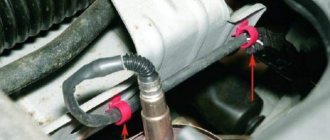
- Remove the sensor together with the housing from the engine air duct. The device is attached with a clamp to the channel and two bolts to the air filter housing.
- Unscrew the two screws securing the sensor to the housing. The bolts have a star head, but many owners unscrew them with pliers.
- Wash the measuring thermistors and the air passage channels with a cleaning agent. If the cleaning method with alcohol is used, the removed sensor is heated with a stream of warm air and placed in a container. The alcohol-water mixture is also heated to 60-70 degrees.
- Dry the sensor.
- Wash the sensor housing with warm soapy water. Rinse under running water and dry.
- Assemble the sensor and install it in place.
Video “Visual instructions for cleaning the mass air flow sensor”
More clear instructions for cleaning the controller are shown in the video below (the author of the video is the IZO)))LENTA channel).
The mass air flow sensor for cars of the tenth family is installed between the air filter and the air duct leading to the throttle valve. The duration of the injector opening pulse, that is, the supply of a combustible mixture to the engine combustion chambers, depends on the accuracy of the mass air flow sensor. If the air flow sensor does not work correctly, or if it is not tightly installed on the filter and air duct, there may be a deviation from the rated frequency of the engine, and a drop in its power is also possible.
How to replace the air flow sensor on a VAZ 2110
Crankshaft sensor for VAZ 2112 16 valves
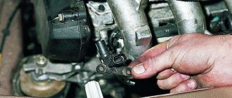
Replacing the sensor yourself is not difficult. After the operation of the device has been checked and if there is no point in cleaning the sensor, you can begin to replace it.
- The car is placed on a flat surface, and the negative terminal must be removed from the battery.
- Then the sensor is turned off.
- To remove the clamping bolt of the clamp, use a screwdriver; it is located on the corrugation.
- We remove the corrugation.
- Then unscrew the bolts on the air filter.
- Now you can remove the old sensor and install a new one in its place.
- You can reassemble in reverse order.
If all the work is carried out correctly, the car will again regain power and dynamics, and the sign on the instrument panel will disappear. To check the correct operation of the MAF sensor, you should drive the car. If everything returned as it was before the breakdown, then the repair was carried out correctly, and the cause was the DMVR sensor.
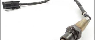
Mass air flow sensor device (English abbreviation - MAF)
- The housing is made in the form of a cylinder, the diameter of which coincides with the air duct of the intake manifold. Installed at the outlet of the air filter (using the example of a VAZ 2112). The housing itself is a calibrated measuring channel.
- To protect against foreign objects, a deflector and a metal screen in the form of a mesh are installed at the entrance. The correct air flow is formed through them.
- The air flows through the flow sensor itself, which operates on the thermal anemometric principle. There are two resistors installed inside (reference and variable), connected to a common circuit using a ballast circuit. Variable, precision, changes resistance when cooling and heating. The thread of this resistor is made of an alloy of iridium and platinum. The control board monitors that the resistance is the same. To do this, a platinum thread cooled by an air flow is heated by electric current. The resistor is constantly supplied with voltage, the value of which varies with an accuracy of 1/1000 volt.
- The value of this voltage is output by the MAF circuit to pin No. 5 of the connector. The signal is read by the ECU controller and programmatically converts this value into air mass (kg/hour).
Cleaning the sensor
If you observe signs of a malfunction of the mass air flow sensor, then you can try cleaning the device.
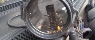
By the way, this is the most expensive sensor of all in the line of front-wheel drive VAZ cars. But if yours is broken, don’t rush to change it. There is a small chance of restoring his “health”.
For the cleaning process you will need a special liquid that is used to clean the carburetor. Star keys are also useful. Unscrew the clamp, as well as the two “10” bolts.
Remove the pipe and take out the sensor. Spray the liquid onto the wire and tube. Work with extreme care, wait until this liquid has completely evaporated and leave the device to dry.
While the device is drying, remove the throttle assembly. You will see plaque inside the throttle assembly. It needs to be removed with liquid.
This dirt causes problems with the entire system. Because of it, problems with the mass air flow sensor appear, signs of a malfunction of the VAZ 2115, which bother beginners on automobile forums.
Do not remove the throttle cable. Place the knot on a cloth and treat particularly dirty areas with the liquid. Don't forget to clean the idle air control valve and the space underneath it.
After this, most likely, all signs of problems with the mass air flow sensor will go away, of course, provided that the sensor has no mechanical damage. Therefore, do not wait until you have the first signs of such problems, but take such prevention this coming weekend. It won't take you much time, and your car will truly breathe.
You won't recognize your engine. It will start much better, its traction will improve, and you will notice an increase in the power of your engine.
Carry out such preventive maintenance regularly, and your car will thank you.
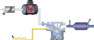
The automotive market does not stand still; manufacturers are constantly improving car engine power, fuel consumption, aerodynamic values, and coming up with options for changing overall comfort. The main and obvious improvement was the transition from the use of a carburetor method of power supply to a more efficient injection system.
How does the latter work? Regulates the quantitative supply of fuel according to a single dosage for the operation of the power plant in different formats of activity. This allows you to reduce the amount of air consumption and ensure maximum power output from the power structure.
However, mechanics argue that the design of the carburetor system is technologically simpler, because the carburetor operates mechanically, which means that the mechanism can be assumed to be highly reliable. The VAZ-2110 is equipped with such a system. The advantage of the device is that the fuel-air mass is formed in the carburetor and in the cylinders through vacuum, which is created by the pistons.
- how is the crankshaft positioned?
- what is the rotation speed;
- how much air enters the cylinders;
- what volume is contained in the exhaust gas;
- where is the throttle valve located.
These data and the calculation of the required fuel are responsible for the sensors recorded in the individual components of the power product - mass air flow sensor, which we will look at in more detail right now.
Interchangeability
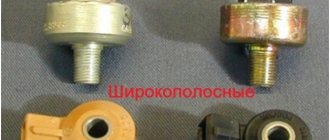
This issue is quite relevant, especially taking into account the cost of original products from the imported automobile industry. But it’s not so simple here; let’s give an example. In the first production models of the Gorky Automobile Plant, the injection Volgas were equipped with a BOSCH air flow sensor. Somewhat later, imported sensors and controllers replaced domestic products.
A – imported filament air flow sensor manufactured by Bosh (pbt-gf30) and its domestic analogues B – JSCB “Impuls” and C – APZ
Structurally, these products were practically no different with the exception of several design features, namely:
- The diameter of the wire used in a wirewound thermistor. Bosch products have a diameter of 0.07 mm, and domestic products have a diameter of 0.10 mm.
- The method of fastening the wire differs in the type of welding. For imported sensors this is resistance welding, for domestic products it is laser welding.
- Shape of a thread thermistor. Bosh has a U-shaped geometry, APZ produces devices with a V-shaped thread, and products from JSC Impulse are distinguished by the square shape of the thread suspension.
All the sensors given as an example were interchangeable until the Gorky Automobile Plant switched to film analogues. The reasons for the transition were described above.
Film air flow sensor Siemens for GAZ 31105
It makes no sense to give a domestic analogue to the sensor shown in the figure, since outwardly it is practically no different.
It should be noted that when switching from filament devices to film devices, most likely, it will be necessary to change the entire system, namely: the sensor itself, the connecting wire from it to the ECU, and, in fact, the controller itself. In some cases, the control can be adapted (reflashed) to work with another sensor. This problem is due to the fact that most filament flowmeters send analog signals, while film flowmeters send digital signals.
It should be noted that the first production VAZ cars with an injection engine were equipped with a filament air flow sensor (made by GM) with a digital output; examples include models 2107, 2109, 2110, etc. Now they are equipped with air flow sensor BOSCH 0 280 218 004 .
To select analogues, you can use information from official sources or thematic forums. As an example, below is a table of the interchangeability of mass air flow sensors for VAZ cars.
Compatibility table for mass air flow sensor for the VAZ model range
The presented table clearly shows that, for example, the MAF sensor 0-280-218-116 is compatible with VAZ 21124 and 21214 engines, but is not suitable for 2114, 2112 (including those with 16 valves). Accordingly, you can find information on other VAZ models (for example, Lada Granta, Kalina, Priora, 21099, 2115, Chevrolet Niva, etc.).
As a rule, there will be no problems with other brands of cars of domestic or joint production (UAZ Patriot ZMZ 409, Daewoo Lanos or Nexia), choosing a replacement mass air flow sensor for them will not be a problem, the same applies to products of the Chinese automobile industry (KIA Ceed, Spectra, Sportage etc.). But in this case, there is a high probability that the MAF pinout may not match; a soldering iron will help correct the situation.
The situation is much more complicated with European, American and Japanese cars. Therefore, if you have a Toyota, Volkswagen Passat, Subaru, Mercedes, Ford Focus, Nissan Premiere P12, Renault Megane or another European, American or Japanese car, before replacing the mass air flow sensor, you need to carefully weigh all the solution options.
If you are interested, you can search online for an epic about an attempt to replace the “native” air meter with an analogue on a Nissan Almera H16. One attempt resulted in excessive fuel consumption even at idle.
In some cases, searching for an analogue one will be justified, especially if you take into account the cost of the “native” VU meter (for example, the BMW E160 or Nissan X-Trail T30).
Symptoms of a faulty air flow sensor
If the mass air flow sensor begins to produce incorrect data, then a failure occurs in the system for preparing the fuel-air mixture, and the proportions of fuel and air are disrupted. This results in the following symptoms of a malfunction:
- Unstable idle speed
- Violation of the smooth running of the car
- Difficulty or impossible to start the engine
- Noticeable deterioration in vehicle dynamics
- Increased fuel consumption
- The yellow "Check Engine" light on the instrument panel does not go out
Check engine light on the instrument panel
If the Check Engine light is constantly on on the instrument panel, the easiest way to check, if you have a diagnostic tool, is to read the error codes, which will allow you to pinpoint the problem. One of the most common DMRV errors is error p0100. Explanations of diagnostic codes can be found in the technical literature for a specific vehicle.
None of the above symptoms are a 100% guarantee that the mass air flow sensor has failed. Other vehicle systems may also be to blame. But all these symptoms together, or each one separately, give reason to check the flow meter for performance.
What is a DMRV?
This device is very necessary in order to determine the volume of air that fills the combustion chambers when the engine is running. The sensor is usually installed after the air filter in the power system.
When driving, the automobile power unit is supplied with 1 volume of fuel, as well as 14 equal parts of air. This prepares the correct fuel-air mixture. This is the key to proper operation of the motor in the most optimal modes for it.
For any violation of this ratio, the car owner will observe either increased fuel consumption, or a decrease in the power of the power unit, or both. If you know the signs of a malfunction of the mass air flow sensor, it is easy to identify a breakdown of the device.
The mass air flow sensor is necessary in order to accurately measure the required amount of air. This amount is calculated in the sensor itself and then sent to the ECU, where, based on these data, the required amount of fuel will be calculated.
The more the driver presses the accelerator pedal, the more air enters the combustion chambers. The sensor records the amount and sends a special command to the ECU to increase the volume of injected fuel. If the car is to run or drive more smoothly, then a small amount of air will be needed.
This is why you need a mass air flow sensor. It measures the required volumes of air for engine operation with maximum accuracy.
Checking the air flow meter
One way to check the air flow sensor
There are several ways to detect a malfunction of this sensor. The easiest way is to disconnect the power supply from the sensor while the engine is running. After the chip is turned off, the control unit goes into emergency mode, in which fuel dosage is carried out according to the readings of the throttle position sensor. In this case, the idle speed will begin to increase to over 1500 revolutions, although not always; some injection systems do not increase the speed.
With the flow meter turned off, you need to drive the car. If the performance of the power plant has improved, most likely there are problems with the mass air flow sensor.
Video: Demonstration of a faulty mass air flow sensor on Kalina, Priora, Grant, VAZ 2110-2112, 2114-2115
Some sensors can be checked using a voltmeter or multimeter with high precision settings. The measuring device is connected with a “positive” probe to the MAF signal wire (usually the far right wire), and with a “negative” probe - to the ground wire of the sensor. Then you need to turn on the ignition, but do not start the power plant. A working sensor should have a voltage between 0.9 and 1.4 V. The readings above indicate a sensor malfunction.
Very often the failure is caused by contamination of the working elements of the sensor. Therefore, a visual inspection can also indicate a malfunction.
If the working elements of the sensor are noticeably heavily soiled, this is most likely the cause of problems with the operation of the power plant. But restoration work can be done with sensors based on a pitot tube. They can be removed from dirt by washing with a carburetor cleaning spray.
Let's summarize
From the above, we can conclude that you can check the VAZ 2110 mass air flow sensor using a multimeter yourself. By comparing the ADC readings with computer diagnostics, we can say that the test with a multimeter is correct.
It is also worth noting that if you want to maximize the life of the air flow sensor, change the air filter more often. The manufacturer recommends replacement every 30 thousand kilometers. We recommend reducing this interval to 20 thousand kilometers, and if you mainly travel on dusty roads to 15 thousand km. mileage
The process of replacing the MAF VAZ 2110, 2111, 2112 is clearly shown in this video:
Source
When you need to change the DFID sensor 2110: symptoms of sensor malfunction and check
During the operation of a vehicle, the mass air flow sensor 2110 can fail for various reasons, one of which is the long period of use of the device. When a sensor fails, it is usually not repaired; it is simply replaced with a new one. The following symptoms may indicate that the sensor is not working properly:
- “Check Engine” lights up on the car’s dashboard (you need to check the engine);
- fuel consumption increased, acceleration dynamics decreased;
- the car engine does not start;
- at idle, the car’s internal combustion engine operates jerkily (change in idle speed down or up).
All of the listed signs of sensor malfunction indicate that air is not being supplied to the mixture in the volume required. Taking into account the fact that this problem may be associated not only with a malfunction of the mass air flow sensor, before proceeding with dismantling the sensor, it is necessary to make sure that it is faulty.
In fact, the VAZ 2110 mass air flow sensor can be checked for performance using three methods: in motion, with a multimeter, visually. Checking the mass air flow sensor 2110 experimentally (in motion) is the easiest and fastest way. It consists of analyzing the operation of the vehicle’s internal combustion engine when the sensor is forcibly turned off.
Algorithm of actions:
opening the hood, disconnect the mass air flow sensor connector; start the car engine; since the car will operate in emergency mode, the “Check Engine” light will come on and the amount of air in the fuel mixture will be determined depending on the throttle position; Having driven a car operating in emergency mode, you need to pay attention to its dynamics and compare them with the dynamics before the sensor was turned off; If the car accelerates faster with the sensor turned off, the air flow sensor is faulty.
The next stage of diagnosis may be checking the mass air flow sensor 2110 with a multimeter. This method of checking the sensor for functionality involves the use of a measuring device (multimeter).
Before checking, you need to understand the design of the device and find out its “pinout” (soldering of wires on the board). There are four wires coming out of the MAF. Typically these are the wire to the main relay (pink/black or pink), ground (green), power (gray), and signal input (yellow).
To check you need:
- set the multimeter to constant voltage measurement mode, setting the limit to 2 Volts;
- without starting the engine, turn on the ignition;
- connect the black multimeter probe to the ground wire, the red one to the signal input of the multimeter sensor, inserting the multimeter probes through the rubber seal of the connector;
- take measurements and use the results to determine the state of the sensor.
Based on multimeter readings:
- voltage 0.996-1.01 Volts (new sensor);
- voltage 1.01-1.02 Volts (working sensor in good condition);
- voltage 1.02-1.03 Volts (sensor working, with long-term operation);
- voltage 1.03-1.05 Volts (sensor is worn out and may fail);
- voltage from 1.05 Volts and above (the sensor is faulty and requires replacement).
If the device is not at hand, the faulty sensor can often be determined by its appearance, that is, by visual inspection. In this case, it is necessary to dismantle the device and carefully inspect it for mechanical damage or for the presence of liquid in the sensor and air pipe.
The reasons for liquid and dirt getting into the sensor can be different (for example, the oil level in the crankcase is increased, dust gets on the hot-wire anemometer due to untimely replacement of the air filter, the oil sump of the crankcase ventilation system is clogged, etc.).
Flow meter failure: signs and causes of failure
Of course, the absence of a sensor or incorrect readings will not lead to a complete stop of the car. Moreover, the mass air flow sensor is checked, among other things, by the on-board computer. However, the symptoms will not allow you to move normally on the road:
- loss of engine power, up to the inability to drive uphill;
- engine jerking when moving evenly;
- hanging at high speeds after releasing the gas (this can be dangerous);
- increase in fuel consumption up to two times;
- engine vibrations reminiscent of “triple movement”, leading to increased wear of mechanisms.
With the exception of natural wear (any mechanism has a service life), other causes of malfunctions are associated with contamination of the MAF sensors or moisture and oil entering it. These problems arise due to an irresponsible attitude towards car maintenance.
- untimely replacement of the air filter;
- installation of low-quality or “zero” filters;
- water getting into the air duct channel (driving through puddles at high speed, careless car washing);
- penetration of oil vapors into the flow meter housing due to a malfunction of the crankcase ventilation system;
- debris and foreign objects that have entered the measuring channel after repair work or car maintenance.
Advice: do not rush to change a clogged flow meter; you can try to clean it with compressed air or a special aerosol for mass air flow sensors or carburetors.
System depressurization
If depressurization occurs in the intake tract system, then instability in engine operation occurs. Air leaks occur in the following parts of the car:
- In sealed areas of the nozzle;
- On exhaust systems for gasoline vapors;
- On the walls of the throttle frame;
- On idle jets;
- On the vacuum brake booster pipes;
- On the cleaning pipes.
Due to improper air removal, improper mixing of fuel masses occurs. Emergency symptoms are detected during the operation of the intake tract. The air leaving the system does not pass through the filtration system. It contains many harmful particles of dirt, metal, and plastic, which enter the engine and threaten to lead to poor performance of the latter.
What is the difference between sensors 037 and 116?
How can the regulators of these models differ from each other and is it possible to install 116 instead of 037? There are differences between these controllers, and the point is not in the MAF pinout. After all, if these models were the same, what would be the point of giving them different names?
So, how do the controllers differ from each other and is it possible to install model 116 instead of 037:
- The first difference that can be guessed based on the technical characteristics is that the 037 model can produce data with an error during operation. Of course, an error of 2.5% is not critical, but it does exist.
- Device 037 is intended for installation in VAZ 2111, 2112, 2123, 21214 cars, which are equipped with controllers M 1.5.4, January 5.1-5.1.3, etc.
- As for model 116, its use is relevant on Ladas 21114, 21124, 21214. Installation of this device is allowed on Kalina and Priora. Installation of the device is allowed on cars equipped with M 7.9.7 and January 7.2 controllers.
If you encounter a problem with the device not working, then when replacing it you need to install the same model that has already been installed. But it is worth considering that 037 is not a common option like 116, so it is more difficult to find. The latter, in turn, is more common, and its cost is lower.
Replacement is allowed, but experts do not recommend this. This is because these devices differ in their calibration, so in case of replacement, you will have to change the parameters of the control unit. And you can only get into the “brains” of a car if you understand what needs to be done and have minimal experience.
Loading …
Description of ADS1115 registers
The ADC has only 4 internal registers, all registers are 16-bit, respectively, for each write/read session, 2 information bytes are transmitted via the I2C interface (except for the register address byte). The registers are described in the table below:
| Address | Name | Register description |
| 0x00 | Conversion register | Conversion result storage register |
| 0x01 | Config register | Configuration register |
| 0x02 | Lo_thresh register | Setpoint register, minimum value |
| 0x03 | Hi_thresh register | Setpoint register, maximum value |
The configuration register is used to control the ADC; the register is described in the table below:
| Bit | Bit name | Bit value | Description |
| 15 | OS. The bit defines the state of the device and can only be written in low power mode | For recording | |
| 0 | No effect | ||
| 1 | Start conversion, for single conversion mode (low consumption) | ||
| For reading | |||
| 0 | Conversion in progress | ||
| 1 | Conversion complete | ||
| 14-12 | MUX. Multiplexer setup | 000 | AINp=AIN0 and AINn=AIN1 (default) |
| 001 | AINp=AIN0 and AINn=AIN3 | ||
| 010 | AINp=AIN1 and AINn=AIN3 | ||
| 011 | AINp=AIN2 and AINn=AIN3 | ||
| 100 | AINp=AIN0 and AINn=GND | ||
| 101 | AINp=AIN1 and AINn=GND | ||
| 110 | AINp=AIN2 and AINn=GND | ||
| 111 | AINp=AIN3 and AINn=GND | ||
| 11-9 | P.G.A. Amplifier Gain | 000 | FS=±6.144 V |
| 001 | FS=±4.096 V | ||
| 010 | FS=±2.048 V (default) | ||
| 011 | FS=±1.024 V | ||
| 100 | FS=±0.512 V | ||
| 101 | FS =±0.256 V | ||
| 110 | FS =±0.256 V | ||
| 111 | FS =±0.256 V | ||
| 8 | MODE. Operating mode | 0 | Continuous transformation |
| 1 | Single conversion, low consumption mode (default) | ||
| 7-5 | D.R. Sampling frequency | 000 | 8 Hz |
| 001 | 16 Hz | ||
| 010 | 32 Hz | ||
| 011 | 64 Hz | ||
| 100 | 128 Hz (default) | ||
| 101 | 250 Hz | ||
| 110 | 475 Hz | ||
| 111 | 860 Hz | ||
| 4 | COMP_MODE. Comparator type | 0 | Comparator with hysteresis (default) |
| 1 | Comparator without hysteresis | ||
| 3 | COMP_POL. Comparator polarity | 0 | Low active level (default) |
| 1 | High active level | ||
| 2 | COMP_LAT. Comparator mode | 0 | Comparator without latch (default) |
| 1 | Latch Comparator | ||
| 1-0 | COMP_QUE. Comparator control | 00 | Setting the output signal after one conversion |
| 01 | Setting the output signal after two conversions | ||
| 10 | Setting the output signal after four conversions | ||
| 11 | Comparator disabled (default) |
Signs of a malfunction of the mass air flow sensor on a VAZ 2110: how to rinse and clean it yourself
When the first signs of a malfunction occur, you should definitely check the mass air flow sensor, and then, depending on the situation, clean or replace the device.
Now let's talk about how to check our sensor. Today, two main methods of checking the mass air flow sensor are used.
- The engine is tested in operation with the mass air flow sensor disconnected. Simply turn off the power from the regulator and start the motor. When the mass air flow sensor is not present during startup, the electronic control unit turns on the power unit in emergency mode. The speed is adjusted to 1500 rpm. After disconnecting the sensor, drive a few kilometers and evaluate the dynamics and power. If the engine is running normally, then the sensor is the cause of the symptoms.
- The second method will require the use of a car tester or voltmeter. After starting the ignition, do not start the engine. The voltage threshold is set on the tester to 2V. The positive probe connects to the yellow wire on the sensor connector, and the black probe connects to the green wire. Next, refer to the table.
Index
Air flow sensor condition
The sensor is functioning normally
Not ideal, but still acceptable voltage readings
Maximum permissible values that indicate imminent sensor failure
The air flow sensor has failed and needs to be replaced
Quite often you can avoid replacing the mass air flow sensor by simply cleaning this engine element.
You should do the cleaning yourself in this way:
- Remove the pipe from the mass air flow sensor;
- Now remove the sensor from the pipe. Otherwise, high-quality washing will not work;
- To remove the sensor, arm yourself with sprocket keys in advance. Finding such kits is not a problem;
- Unscrew all the fasteners, remove the sensor from the pipe and assess its external condition;
- Often there are traces of oil deposits on the sensor. The purpose of cleaning is to make the device as good as new;
- Carburetor cleaner is often used to clean the air flow sensor;
- Inside the film there are sensors, which are small wires attached to a special resin. These elements must be carefully sprayed with cleaner so as not to damage the devices;
- Wait a while for the surfaces to dry. To speed up the process, use a can of compressed air;
- It is not uncommon to use alcohol instead of carburetor cleaner, which also works quite effectively;
- Proper cleaning of the mass air flow sensor involves treating the pipes from accumulated debris, dirt and dust;
- Having carefully processed all the components of the removed mass air flow sensor, wait until it dries, and then reassemble it. Cleaning is complete.
Spray cleaning
Statistics show that in about 80% of cases, simple cleaning can return the mass air flow sensor to its previous functionality.
Price issue
80% is not 100. Therefore, sometimes you have to change the sensor. And to replace it, you need to buy it.
There are three price categories for air mass flow sensors:
- Cheap. These are predominantly Chinese products, the price of which is up to 1000 rubles. It is strongly not recommended to purchase such regulators;
- Average. These include sensors from AvtoVAZ, domestic and some foreign analogues. These cost from 1500 to 2500 rubles;
- Expensive. High-quality, reliable, imported air flow sensors, the price of which can reach 5.5 thousand rubles. It’s hard to say how rational it is to buy them. But they will definitely last a long time.
It is not difficult to replace the mass air flow sensor with your own hands, even if you do not have any special skills in car repair. Having checked the condition of the device and determined that cleaning will not help, all that remains is to replace it.
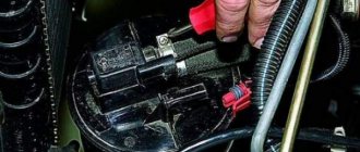
- Place the car on a level surface, lift the hood and remove the negative terminal from the battery.
- Disconnect the sensor connector. We have already talked about its location, so there will be no problems with the search.
- Using a screwdriver, remove the clamping bolt of the clamp that secures the corrugation to the mass air flow sensor.
- The corrugation is removed.
- Using a 10mm wrench, unscrew the two bolts that hold the sensor to the air filter housing.
- After removing the failed oxygen sensor, install a new regulator in its place.
- Screw back a couple of bolts, secure the corrugation and secure it with a clamp.
- Reconnect the connector and return the negative terminal to the battery.
If everything is done correctly and the breakdown is correctly identified, then the engine will return to its previous performance and the error signal on the dashboard will disappear.
Replacing the device
To finally check the result of the repair, go out onto the road, do a test drive and be sure to try to press the gas pedal sharply. If the dynamics and power become the same as before the problems arose, you did everything correctly, and it was the mass air flow sensor that was the culprit of the malfunction.
Troubleshooting methods
You don’t have many options for solving the problem - you can either try to clean the sensor or replace it with a new one.
The cleaning and replacement procedure is described below:
- First you need to dismantle the mass air flow sensor. To do this, loosen the bolt that secures the corrugated hose to the device body, then disconnect it.
- Next, you need to unscrew two more screws, with which the mass air flow sensor is fixed to the air filter housing. Having done this, you can dismantle the controller. If you decide to change it, then you will simply need to install a new mass air flow sensor and perform the assembly in the reverse order. But if you want to try to restore its functionality, you can clean the device.
- After dismantling the regulator, it must be disassembled. There are spirals on the device, so when dismantling the regulator, be careful not to damage them. As practice shows, these spirals are very sensitive; there are even cases where car owners, simply wiping the mass air flow sensor with a rag, put it out of action.
- Now you will need a special carburetor cleaner, which can be purchased at any store. Before cleaning, make sure that the pressure from the cylinder is not strong, since excessive pressure can also damage the device. The device body itself should not be heavily processed, since the plates and spirals are the most contaminated, so these components need to be processed as much as possible. It should be noted that this process must be carried out in several stages. The point is to let the device dry a little after treatment - this will allow the dirt to dry out as much as possible. The procedure must be repeated several times at short intervals; eventually, the air flow sensor will need to be washed. The cleaning process itself is repeated until clear, clean drops of cleaner begin to flow from the sensor. Then you can reinstall the device by assembling all components in reverse order.
Photo gallery “Cleaning the air flow sensor”
How to check the DMRV on a VAZ 2110
Disconnect the sensor connector. Start the engine. Increase engine speed to 1500 rpm or more. Start moving. If you feel the car “swiftly”, this means that the mass air flow sensor is faulty and needs to be replaced with a new one. This is the first check option. If the mass air flow sensor is disabled, the controller goes into emergency mode, so the mixture is prepared only according to the throttle valve.
Turn the tester into DC voltage measurement mode, set the measurement limit to 2 V. The second option for checking the mass air flow sensor. Measure the voltage between the yellow “output” wire (closest to the windshield) and the green “ground” wire (3rd from the same edge), located in the sensor connector. Colors may vary depending on the year of production, but the layout remains the same. Turn on the ignition, but do not start the engine. Use the tester's probes to penetrate through the rubber seals of the connector, along these wires, and reach the contacts themselves without breaking the insulation. Connect the tester and take readings. These parameters can also be removed from the on-board computer display, if available. They are in the group of “voltage from sensors” values and are designated U dmrv.
Evaluate the results. At the output of a working sensor, the voltage should be 0.996-1.01 V. During operation, it gradually changes upward. Using this parameter, you can determine the degree of “wear” of the sensor. For example: 1.01-1.02 V – the sensor is working, 1.02-1.03 V – the sensor is working, but is already “planted”, 1.03-1.04 V – it will soon need to be replaced, 1.04-1.05 V – it’s time to change it, 1.05 V and above – operation is impossible, mandatory replacement.
Inspect the sensor when readings are abnormal. Take a shaped screwdriver and unscrew the clamp of the rubber corrugation of the air inlet, which is located at its outlet. Remove the corrugation and carefully inspect its internal surfaces and the sensor. They should be free of condensation and oil. This is the most common cause of damage to the air flow sensor. If they are, it means the oil level in the crankcase is too high and the crankcase ventilation oil trap is clogged. Before replacing the sensor with a new one. The problem must be corrected.
How to deceive the mass air flow sensor using ECU firmware
The good thing about the previous method is that its implementation does not require complex equipment or painstaking work. If you were able to check the voltage at the output of the flow meter with a multimeter (which means you at least have one), and know how to hold a soldering iron in your hands, installing a resistor in the wire gap will not be difficult. However, the dependence of voltage on air flow mass is nonlinear. And when the throttle valve opens, the error of the signal corrected by the resistor at rest will increase. Accordingly, the fuel-air mixture will not be ideal.
This means that you need to adjust the MAF calibration in the ECU firmware.
Attention! If you do not have experience working with car software, it is better to entrust this operation to professionals.
- We install the specialized tuning program “DFID Corrector” on the laptop.
- We connect the car scanner to the OBD-II connector and establish communication between the ECU and the computer.
Important! During operations with the ECU controller firmware, the 12 volt power supply should not be lost. Therefore, you need to make sure that the battery is fully charged.
- We adjust the voltage of the MAF ADC at rest (air mass 0 kg/hour) to the required 1 V.
- Save the firmware changes.
After calibration, the data on mass air flow will be correct throughout the entire engine speed range.
Attention: After you install a new flow meter, you must return the calibration to the factory (standard) state.
This is interesting: What gap should be on the Hyundai Solaris on the spark plugs
Features, diagnostics and replacement of elements of injection systems on VAZ cars
Below we will look at the main controllers!
Hall
There are several options for how you can check the Hall sensor of a VAZ:
- Use a known working device for diagnostics and install it instead of the standard one. If after replacement the problems in engine operation cease, this indicates a malfunction of the regulator.
- Using a tester, diagnose the controller voltage at its terminals. During normal operation of the device, the voltage should be from 0.4 to 11 volts.
The replacement procedure is performed as follows (the process is described using the example of model 2107):
- First, the switchgear is dismantled and its cover is unscrewed.
- Then the slider is dismantled; to do this, you need to pull it up a little.
- Remove the cover and unscrew the bolt that secures the plug.
- You will also need to unscrew the bolts that secure the controller plate. After this, the screws that secure the vacuum corrector are unscrewed.
- Next, the retaining ring is dismantled and the rod is removed along with the corrector itself.
- To disconnect the wires, you will need to move the clamps apart.
- The support plate is pulled out, after which several bolts are unscrewed and the manufacturer dismantles the controller. A new controller is being installed, assembly is carried out in the reverse order (the author of the video is Andrey Gryaznov).
Speeds
The following symptoms may indicate a failure of this regulator:
- at idle, the speed of the power unit floats, if the driver does not press on the gas, this can lead to an arbitrary shutdown of the engine;
- the speedometer needle readings float, the device may not work as a whole;
- fuel consumption has increased;
- the power of the power unit has decreased.
The controller itself is located on the gearbox. To replace it, you only need to jack up the wheel, disconnect the power wires and remove the regulator.
Fuel level
The VAZ or FLS fuel level sensor is used to indicate the remaining volume of gasoline in the fuel tank. Moreover, the fuel level sensor itself is installed in the same housing with the fuel pump. If it malfunctions, the readings on the dashboard may be inaccurate.
The replacement is done like this (using the example of model 2110):
- The battery is disconnected and the rear seat of the car is removed. Using a Phillips screwdriver, unscrew the bolts that secure the fuel pump hatch and remove the cover.
- After this, all wires leading to it are disconnected from the connector. It is also necessary to disconnect all the pipes that are supplied to the fuel pump.
- Then the nuts securing the clamping ring are unscrewed. If the nuts are rusty, treat them with WD-40 before unscrewing.
- Having done this, unscrew the bolts that directly secure the fuel level sensor itself. The guides are pulled out from the pump casing, and the fasteners need to be bent with a screwdriver.
- At the final stage, the cover is dismantled, after which you will be able to gain access to the FLS. The controller is replaced, the pump and other elements are assembled in the reverse order of removal.
Idle move
If the idle speed sensor on a VAZ fails, this is fraught with the following problems:
- floating speed, in particular, when additional voltage consumers are turned on - optics, heater, audio system, etc.;
- the engine will start to stall;
- when the central gear is activated, the engine may stall;
- in some cases, failure of the IAC can lead to body vibrations;
- the appearance of a Check indicator on the dashboard, but it does not light up in all cases.
ADC codes
ADC code parameters relate to analog sensors of the control system:
Physically, ADC codes reflect the voltage that the sensor produces. Typically, these parameters are used to test sensor circuits. If fault codes occur associated with a low or high signal level of such a sensor, then the control system operates in backup modes. In this case, the value of the parameter related to this sensor is selected either from the emergency table or calculated using specified formulas, for example, the coolant temperature with a faulty temperature sensor increases during engine operation.
If, during a physical change in the parameter measured by the sensor, the ADC code remains a constant value, then the electrical circuit connecting the sensor is inoperative.
ADC values are dimensionless, but for the user in scanner testers they are translated into the voltage that a particular sensor produces.
Therefore, using an ADC code, for example, from an L-probe sensor, you can more clearly evaluate the work in the feedback loop system to maintain the stoichiometric composition of the mixture. If the L-probe sensor is inoperative, then the ADC code is in the range of 0.4-0.7V.
The ADC code value (output voltage) from the throttle position sensor can indicate the lower limit at which the system detects sensor error. A throttle position equal to zero corresponds to a voltage from the sensor of 0.52 V.
When the ignition is on, the output voltage from the mass flow sensor (ADC code) should be 1.00V.
The temperature sensor, throttle position sensor, mass flow sensor are powered by a voltage of 5.00V, which is supplied by the control unit. If the control unit produces an unstable voltage, then the sensor readings will change and the behavior of the system in this case is unpredictable.