The generator is rightfully considered the main component in the electrical network of a car. Thanks to the operation of this device, current is supplied to all energy consumers of the car, from optics and radio to auxiliary devices, such as a navigator and recorder. One of the main elements of this mechanism is the generator stator. You can learn more about its design, diagnostics and winding rewinding in this article.
Design and principle of operation of the generator stator
The stator element consists of the following parts:
- the windings themselves;
- core or package;
- terminals for connection to a rectifier.
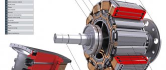
Structurally, the stator device consists of three windings in which three different values of alternating current are generated; this circuit is a three-phase output. One end of each winding is connected to the housing of the generator unit, and the second end is connected to the rectifier device. To strengthen and concentrate the magnetic field in the winding elements, the wires from each winding are laid around the core, which, in turn, must be made of metal plastic.
The winding of the stator device is located in special grooves, the number of which in most units is 36. In the groove itself, the winding is fixed using a groove wedge, which is also made of insulating material.
Performing a build
To assemble the car unit, you need to carry out the reverse sequence of actions. It is necessary to ensure that each part is installed in place and secured with the necessary force. The same fasteners that were originally installed should be used.
It is important to strictly adhere to the pattern and be careful not to apply excessive force, which can lead to breakage of the brushes. If you use a screwdriver to secure car parts, you should not tighten the fasteners all the way. The final rotations must be done manually.
Auto generator assembly
Related video: Generator diagnostics and repair
Publications on the topic
Rules for connecting a generator to the home network
All about the design of a car generator
Operating principle and operating advantages of the HUTER DY6500LX generator
Possible malfunctions: signs and causes
Two types of failures can occur in the operation of the stator mechanism: a break in the windings or a short circuit to ground. As a result of prolonged exposure to humidity and temperature changes, the insulation on the end surface of the core may delaminate and crack. This, in turn, can cause a short circuit and accelerated failure of the unit as a whole. Regardless of the cause, there is only one sign of a malfunction - the generator unit stops functioning normally, problems appear in its operation, and the unit cannot generate current.
Checking the generator stator with a multimeter
How to check the mechanism for damage? Depending on the malfunction, the stator mechanism can be checked for open or short circuit.
To diagnose a break, you will need a multimeter or test light:
- Take the tester and activate it in ohmmeter mode, then connect the probes to the winding terminals. If there is no break in the device, the tester should display a resistance value of about 10 ohms. If there is a break in the device, therefore, current cannot pass to the windings, then the resistance value will tend to infinity. In this case, it is necessary to check all three conclusions.
- As for diagnostics using the control, in this case you will need to apply a negative charge from the battery to one of the contacts of the winding device. To do this you will need an insulated wire. A positive charge will need to be applied through the control to another contact. If the light source starts to light up, this indicates that the device is working normally; if not, then there is a break in the system. The verification procedure will need to be repeated for each output.
As for diagnosing a short circuit, it can also be carried out using a tester or lamp:
- The negative probe of the tester should be connected to the stator, and the multimeter should be set to ohmmeter mode. The positive probe is connected to the winding contact, no matter which one. The procedure is repeated with each output.
- As for diagnostics by control, it is carried out in a similar way. The negative terminal of the battery is connected to the terminal of the stator mechanism, and the positive terminal is connected to any terminal from the battery. If the light starts to light up, this indicates that there is a short circuit in the mechanism; if not, then the device is operating normally. Diagnostics are carried out with each output (the author of the video is the altevaa TV channel).
Car electrical equipment
All electrical equipment of any car is represented by the following components:
- Current sources:
- accumulator battery;
- generator.
Current consumers:
- basic;
- long-term;
- short-term.
The task of the battery is to provide consumers with current while the engine is “resting”, during its startup or operation at low speeds. While the generator is, in fact, the main supplier of electricity. It not only powers all consumers, but also charges the battery.
Its capacity, combined with the power of the generator, must meet the needs of all consumers, regardless of the engine operating mode. In other words, energy balance must be constantly maintained
This is important to know, as it will allow you to understand how the generator stator works
The main consumers usually include the fuel system, including injection, ignition, control, and automatic transmission. Some cars have electric power steering. That is, everything that constantly uses current, from starting the engine to stopping it completely.
Long-term consumers are systems that are not used very often. And this is lighting, security (passive, active), heating and air conditioning devices. Most cars are equipped with anti-theft systems, multimedia equipment and navigation.
As for short-term consumers, these are the cigarette lighter, starting system, glow plugs, signal, as well as comfort systems.
Instructions for rewinding a generator with your own hands
Stator repair involves rewinding the windings.
How to perform this procedure yourself:
- First of all, you need to disassemble the generator assembly and remove the stator from it.
- The existing windings must be burned so that they burn out, but before that you should count the number of turns and make an appropriate circuit for rewinding. In this case, on the stator it will be necessary to mark the locations of the terminals for the beginning and end of the winding. Don’t be afraid to burn it, this will not damage the iron and its magnetic characteristics will not be disrupted.
- After combustion, cleaning is carried out.
- Next, using materials such as syntoflex or press span, it is necessary to cut insulating gaskets. Please note that they should protrude from the ends of the groove by approximately 2.5-3 mm. When one of the gaskets is made and adjusted to size, a piece of tape will need to be cut according to its width or length. Then, using this spacer, cut 36 pieces of the same length and install them in the grooves.
- Then rewinding occurs. The essence of rewinding is that the wiring from one groove goes straight into the fourth, as if in a wave. Having wound half of the turns in one phase, winding is done in the opposite direction, and you need to cover the empty parts of the half-coils. All phases are wound in the same way.
- When the phases are rewound, you will need to seal the grooves by installing the protruding parts of the spacers in them. It is necessary to ensure that the protruding parts of the half-coils do not protrude beyond the boundaries of the metal inward, as well as beyond the boundaries of the fastening from the outside. To do this, tap the coils through the spacers.
- At this stage, you can check and try on the stator in the cover of the generator unit, make sure that the windings do not touch the housing. If there is a touch, then you need to get rid of it.
- Clean and connect the leads of the winding elements; to do this, twist them together and solder them. They will also need to be insulated; for this you can use a textile cambric.
- Before direct connection, you need to make sure that there is no short circuit between the phases, as well as to the metal. If there is a short circuit, then it is necessary to locate the contact point and then insulate it; this will require another gasket.
- After completing these steps, you will need to tie the winding element and secure its contacts with a cord thread. If you don’t have it, you can use linen thread, but not nylon thread, otherwise it will melt and flow when drying. The stator mechanism needs to be warmed up a little, this is done to dry it, and then place it in a container with impregnating varnish or a similar substance. Furniture varnish cannot be used.
- When the device is soaked, hang it up and wait a while until all the varnish has drained. Then it is recommended to place the device in the oven of a regular stove, which needs to be set to minimum heat; it would be better to hang it, and install an old tile under it. Or something similar, the main thing is that the varnish does not flow onto the hot tray. Wait about one hour - if during this time the varnish stops sticking, then at the same temperature you will need to dry the device for about 2 more hours.
Read also: Starline a93 installation instructions
Photo gallery “Independent stator rewinding”
Disassembly procedure
Lada Granta Liftback Logbook Clutch cable It all depends on the degree of damage to its parts. So:
- First of all, use a screwdriver or permanent marker to make a longitudinal mark on the body where the front and back covers separate. This will make it easier to assemble the generator in the future.
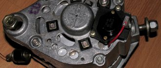
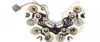
- We press the three spring-loaded latches on the plastic protective casing of the rectifier unit and remove it.
- Using a Phillips screwdriver, unscrew the two screws securing the voltage regulator and lift it up. Then remove the terminal of the appropriate wire from the regulator terminal and carefully remove the regulator completely. Electrically removable brushes are replaced along with the unit.
- Using a size 8 spanner, unscrew the three bolts connecting the rectifier unit to the annular terminals of the stator windings. We carefully move the conclusions to the sides. Remember the location of the thrust and insulating washers on the removed bolts. Now, using a Phillips screwdriver, unscrew the screw securing the noise suppression capacitor to the housing. Disconnect the appropriate wires. We remove the block itself and the capacitor. Using a 10 mm socket wrench, unscrew the two nuts of the contact bolts of the generator and take them out together with the spacer and insulating sleeve, and release the capacitor tip. It is worth noting that wear (or damage) of brushes is the most common cause of malfunction of the generator.
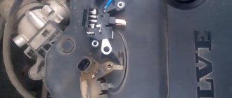
- Using a size 8 wrench, unscrew the 4 bolts holding the rear and front covers of the electric generator together. We push them apart with a face screwdriver and remove the back cover along with the stator winding.
- We remove the stator from the cover, having previously marked it with a mark of their relative position.
- If the front bearing needs to be replaced, remove the generator pulley. To do this, use a 22mm socket wrench to unscrew the nut securing the pulley to the rotor shaft, carefully holding it with pliers or wedging the rotor with a screwdriver. Do not damage the impeller blades, which are made of thin metal.
- Carefully remove the pulley, washers and spacer bushing.
- We return the nut to the rotor shaft, screwing it flush with the end of the armature shaft. Using a rubber hammer, knock the rotor (armature) out of the cover.
- If it is necessary to replace the front bearing, then to remove it, we clamp the front cover by the mounting ear in a vice, the jaws of which are covered with special pads made of soft metal or lined with fabric. Using a mandrel, press out the bearing.
- To replace the rear bearing, secure the armature (rotor) in a vice with pads and remove the rear bearing using a universal puller. If you don't have a puller, use two slotted screwdrivers. 8 nuts are placed under them as supports for lever screwdrivers.
- Removing the slip ring block. First of all, we remove the protective casing (cross) of the rotor contacts from the armature. Then we move these contacts to the sides and remove the slip rings from the rotor.
This completes the disassembly of the electric generator of the VAZ-2110 car. If any part breaks down, it must be replaced with a new one or, if possible, repaired. The generator is assembled in the reverse order.
Video “Visual instructions for rewinding”
How to avoid mistakes when performing this task - see the video below (the author of the video is the sypostat1 channel).
Photo of my fourth homemade wind generator, more about it here - DIY wind generator
Below I will describe a simple example of making a low-power (100-300 Watt) wind generator from a car generator that I made. making a wind generator with your own hands seems easy, but when you start making it, a lot of questions arise, and if you don’t find the answer to them and do it as best you can, then nothing good will come of it.
A car generator can easily be converted into a low-speed generator for a windmill, without any multipliers or other complications. The alteration consists of rewinding the stator and converting the rotor to neodymium magnets, just a couple of days and the generator is ready.
To get started, you will need any auto generator, no matter how many teeth there are on the stator and what car the generator is from, it can be used or burned out. You will also need neodymium magnets, which can be found in local radio parts stores or ordered online.
Magnets need to be dialed into 12 or 24 magnetic poles, depending on how many “teeth” the stator has. You can use either whole magnets of suitable sizes, for example 25*10*6 mm, or take smaller ones and arrange poles to fill the entire free area on the rotor. The larger the area and thickness of the magnets, the more powerful the resulting generator will be.
But there is a limit to everything, and if you use too thick and powerful magnets, there will be a lot of sticking of the rotor to the stator teeth. And the excess magnetic field will go beyond the stator and it will become magnetized from the outside, and this magnetic field will not participate in the generation of electrical energy. In most cases, even thin magnets 20*10*2 mm are enough. See more details on how to make and calculations of generators in the sections of the site.
You will also need copper enamel wire. If you use magnets with an attractive force of no more than 4 kg, then it is better to wind them with 0.6 mm wire, but if the magnets are stronger, then you can wind them with a thickness of 0.8-1 mm. The thicker the wire, the lower the resistance of the generator winding, which means the higher the current, but with a thick wire it will be possible to wind fewer turns, which will result in lower voltage. Therefore, you need to choose something in between, so that battery charging begins already at 200-300 rpm, and the generator power is high.
For example, the generator can be wound with a 0.3 mm wire, then charging will begin almost immediately as soon as the generator starts to rotate, but the current strength will be very small, and if you do not rewind the generator at all, then the current strength will be large, but the voltage will not be enough to charge the battery, since the wind will not be able to spin the wind generator screw to 2000-3000 rpm. If you wind with wire 0.6-0.8 mm, you can’t go wrong, this is optimal with magnets 25*10*6 mm / 30*10*5 mm / 30*10*4 mm, etc. When winding into the grooves, you need to put turns as as much as possible so that there are no gaps, so more turns will enter, and that means the voltage will be higher. You can read more about generator calculations here - Calculation of generator voltage and power
Once you have the magnets and wire, you can take the rotor and go to a turner so that he can sharpen the rotor for the magnets. The rotor needs to be ground to the thickness of the magnets and sleeve. The sleeve is needed to close the magnetic field of the magnets, this increases the power and efficiency of the magnets. The thickness of the sleeve is usually equal to the thickness of the magnets. The rotor is infiltrated and a liner is put on, it is either welded or filled with epoxy resin.
Read also: Crankcase gas filter VAZ 2107
By the way, get ready for the fact that turners do not like to sharpen the rotors of auto-generators, as the “crabs” knock during processing, and this negatively affects the machine. If the turner does not want to sharpen the “crabs” of the rotor, then ask him to turn a new rotor from a solid blank, just the same diameter as the magnets. When you sharpen the rotor, then calculate the gap between the magnets and the stator and make it 1 mm, for example, the stator of an auto-generator from a classic with an internal diameter of 89 mm, if the magnets are 5 mm thick, then we drop 10 mm and 2 mm for the gap, and that’s in general The rotor diameter should be 12 mm less than the inner diameter of the stator.
In the case of an auto-generator, the magnets must be glued without any bevel, which reduces sticking so that the rotor moves with less force. The bevel is acceptable for asynchronous motors since there is a long rotor, but the auto-generator has a short rotor and in order to achieve a noticeable reduction in sticking, you need to make a bevel to the width of the tooth + groove. At such a bevel, 30-40% of the power will be lost due to the ineffective placement of magnets under the bevel.
Magnets on the rotor are usually glued with super glue, and then wrapped with tape and filled with epoxy resin. I don’t glue them at all, but simply place them on the rotor through paper spacers between the magnets so that they do not move, and then wrapped with tape and filled with epoxy resin.
How to rewind a generator stator
The new winding is wound not on three teeth, but on each coil a tooth, and the number of coils will be not 18, but 36. if the stator is 36 teeth. You can make random winding, that is, first wind all the coils on a homemade machine, and then tuck them into the grooves. But I wind it directly on the teeth, first insert insulation from thick cardboard and wind a turn directly onto the tooth. This way it turns out smoother and denser, although this painstaking process takes a lot of time, but less copper is wasted and the resistance of the generator is less due to the small frontal parts of the coils. The more turns you can fit, the better; the more copper, the more efficient the generator in general.
The coils are wound in a three-phase pattern, all in the same direction. For example, if the generator is 18 teeth, the first phase is 1,4,7,10,13,16 teeth, the second is 2,5,8,11,14,17 teeth, the third is 3,6,9,12,15,18 teeth. After winding, the stator is usually impregnated with varnish, but I simply coat it with epoxy resin. It is better to lead the beginnings and ends of the phases outside the generator; there should be six wires, and then connect them with a star or triangle. More details can be found here about connection diagrams How to make a wind generator from a car generator
Preparation
In any case, before moving on to direct work, you should prepare the necessary tools. To rewind the unit you won’t need many tools, but you will definitely need a winding machine. Thanks to this equipment, you can easily wind the coils.
It is better to immediately acquire a winding machine with a counter function. This way you can control the number of turns.
In addition to the machine, you will need copper wire of the required size and a tamping tool.
Additional tools that are welcome include a lathe and a drying-burning oven. The latter will help to quickly dry the stator after applying the varnish.
If you don’t have a professional oven, you can dry it under a 100-watt light bulb, but it will take noticeably longer.
Dryer
Yes, and be sure to prepare a container where the stator will be impregnated with varnish. Of course, you need to keep the required tools on hand for each time: a hammer, a screwdriver, pliers, etc.
Experienced motorists and specialists also recommend using a ruler to take the necessary measurements of the length and width of the part.
Connection of windings of a three-phase generator
The star is connected like this: all the beginnings or ends are together, and the remaining three outputs are connected to a diode bridge. A star gives more voltage at the same speed compared to a triangle, so charging starts earlier, and a triangle gives more current, but charging starts at higher speeds. The difference between star and triangle in current and voltage is approximately 1.7 times.
The triangle is connected like this: the end of the first phase with the beginning of the second, and the end of the second with the beginning of the third, and the end of the third with the beginning of the first, these three points are connected to the Larionov diode bridge, this is the standard bridge of the auto-generator.
When the generator is finished, that is, it is working and generating electricity, by the way, it is advisable to spin it and measure all the data. At 300 rpm you should get about 20-30 volts at idle and 2-4 Amps to the battery. If so, then everything is fine with the generator. Measure the rotor starting moment; if it is about 0.2-0.4 Nm, then everything is fine, but if it is more, then there may be problems with starting the propeller in light winds. You can probably figure out how to make a frame with a tail and a rotary axis yourself. But the screw is a complex matter, and a little more about it.
Installation
When the insulation has completely hardened, install the restored generator, screwing it tightly to the standard seat. Close the cover and reassemble the motorcycle in reverse order. With the vehicle in an upright position, rock its suspension and check to see if an oil leak has formed after installing the generator, which could cause significant problems in the future. Start the motorcycle and remove the terminal connected to the battery charging relay.
Check the voltage that the generator produces using a multimeter or voltmeter. Under normal conditions, it should be 13.8–14.5 volts. If there is a strong deviation in any direction, it is worth removing the generator and finding the mistake made when winding it. If the problem is not corrected, the motorcycle's electrical system may be severely damaged, which will only make the problem worse. If you followed the correct sequence of actions, but failed to increase the voltage compared to the original value, you will have to install a new generator.
Manufacturing of wind turbine blades
Homemade screws for low-power wind generators are usually made from PVC pipes 110, 160 mm. By the way, I also made it from ordinary galvanized sheet metal with a diameter of up to 1.2 m, but there seems to be nothing better than pipe in terms of strength and ease of manufacture. Although you can make wooden blades, or glass-plastic ones, or buy ready-made ones tailored to the power and speed of the generator.
Wind turbine propellers are usually designed to produce maximum power in certain winds. The so-called KIEV (wind energy utilization coefficient) greatly depends on the shape and geometry of the blade. But we will not go into calculations, since there is a ready-made calculated propeller made of PVC pipe with a diameter of 1.5 m. The photo shows the data for the manufacture of blades.
Scheme
It is important to draw a diagram before winding the winding. For example, in a 1-phase generator, the windings are connected according to the principle of linearity. In other words, the beginning of the 1st part of the winding is similar to the beginning of the 2nd phase, the end of the 3rd is the end of the 4th, the beginning of the 3rd is the beginning of the 4th, etc.
But in a 3-phase generator the connection is made in a different way. The beginning of the 1st winding is the end of the 2nd, the beginning of the 2nd is the end of the 3rd, etc.
A three-phase generator also often uses a star or delta circuit. If you use a winding assembled in a star circuit in a generator, the voltage will increase by one and a half times or more. In a delta connection, the voltage will be equal to the standard one.
Coordinates for cutting a blade from a pipe
By the way, it can also be cut from the 110th pipe, just reduce the size by one and a half times, and the screw will work perfectly. But the 110th pipe has a wall thickness of only 3.2 mm, and in a strong wind the so-called flutter will appear - the growling of the propeller at high speeds due to the deflection of the blades, so it is better to make it from the 160th pipe with a wall thickness of 4.9 mm, with it the flutter effect not visible.
Below are new photos of my generator. Out of boredom, I decided to experiment with the rotor magnets, and at the same time take photos of the wind generator.
Firing old insulation
The most important stage of the work is firing the old insulation. The process is not dangerous for the metal with its magnetic properties, but dismantling and cleaning the part is greatly simplified. It is recommended to measure the depth of the front projections before firing.
Measuring the protrusions is critical for some generator models. If this is not done, then the protrusions will not be retracted back into the body after collection due to the winding being too thick.
Wind turbines in the country
I’ll end here for now, for more details about these windmills and others, see the sections, and if anyone needs calculations, I suggest you look further at other articles.
Read also: Skoda Fabia is leaking antifreeze
Calculation of blades from PVC pipes The article contains many ready-made, calculated propellers for selection for your wind generators. And also calculation tables. The calculated propellers have all the necessary data, including the coordinates of the blade pattern for cutting from pipes.
Calculation of the folding tail Protecting the wind generator from strong winds by displacing the wind head relative to the rotary axis and using the folding tail. Excel calculation tables, as well as formulas and a description of the operating principle of this design for protecting a windmill from a hurricane.
Generator calculation A simple example of calculating the main parameters of a three-phase permanent magnet generator. I tried to write as clearly as possible for beginners the calculation process and what’s what, what the parameters of the generator depend on.
At first glance, rewinding the stator seems to be a difficult and impossible job at home, which even electric motor winders do not always undertake. But in fact, once you have achieved some experience, a simple three-phase stator can be rewinded in four hours, including all preparatory operations.
This photo shows what a burnt winding looks like. Anti-icing reagents do not spare the insulation, but on foreign cars, even on trucks, for some reason the generator is located in the dirtiest place. Green oxides are noticeable and the short circuit on this stator arose precisely because of the destruction of the insulation. This generator has only gone through 120k miles in a year and a half.
Here you can see how viciously the old insulation is burned, but this does not spoil the iron, the magnetic properties are not impaired. But it makes disassembling and cleaning the stator easier. Before burning the windings, you need to measure the length of the protruding frontal parts. For some generators this is critical (it will not fit into the housing), for others it is not critical, but it is better to try to do it the way it was.
Now you need to count the number of turns and draw a winding diagram, marking on the stator the locations of the terminals of the beginnings and ends of the winding.
The stator has already been cleaned with a steel brush and prepared for winding.
Now it is best to use a special insulating material called syntoflex; it is very durable and when wound with a thick wire it will not be cut at the exits from the groove. Or from presspan, but you need to work with it more carefully, watch for kinks in the wire when leaving the groove, you need to cut insulating spacers protruding from the ends of the groove by 2.5-3 mm on each side and, when tightly laid in the shape of the groove, protruding from the groove by 3, 5-4mm This will make the subsequent sealing of the grooves easier: you won’t have to cut off the excess. Having made and adjusted one gasket, you need to cut the tape along its width or length and, applying a sample gasket, cut thirty-six similar ones and put them in the grooves.
The beginning of the first winding. It can be seen that the wire runs in a wave from the first groove to the fourth.
Having wound half the turns of one phase, we continue winding in the other direction, overlapping the empty frontal parts of the half-coils. The photo shows that the rotation begins in the groove with the terminal of the beginning of the winding. Here you can notice that although the wire went in the other direction, the direction of the current in the groove did not change. Not all stators are wound this way, but it’s better: the frontal parts are filled more evenly and there is less hassle when crimping the protruding part of the finished winding.
Here is one phase wound. Its end is marked with a ring. The remaining phases move similarly to the first.
There are already two, the beginnings and ends of the windings come out in increments through one groove.
Here are all three phases fully wound. Now you need to seal the grooves by placing the protruding parts of the gaskets in them; in the photo they are already laid. And tap the protruding parts of the coils through the birch spacers, so that in the gap they do not protrude beyond the iron inside and beyond the fastening belt outside. In this form, you need to try on the stator in the generator covers and check whether there is any contact between the winding and the housing, and if there is, it’s not too late to fix it. Clean and connect by twisting and soldering the terminals of the ends of the windings. It is better to insulate with a piece of textile cambric. Before connecting, it’s a good idea to check if there is a short circuit between the phases and to the iron. This can happen during a “power” assembly. In this case, it is not too late to find the contact point and isolate it with an additional gasket.
Now you need to tie the winding together like a sausage and secure the terminals with cord thread, if there is none, linen; you cannot use nylon and other thermoplastics - they will leak when drying.
For impregnation, you need to slightly warm up the stator and immerse it in impregnating varnish GF 95 or similar. No furniture will do. After impregnation, you need to let the excess varnish drain and place it in the stove of a gas or electric stove turned on at the lowest heat, on a grate or hang it from a grate, and put something fireproof under the stator - a tile, so that it does not drip onto the hot pan. If after an hour the varnish stops sticking, then the temperature is correct and dry for another two hours. This is the simplest thing. If you like rewinding, you can make a special oven for drying with a stable temperature. You can also dry it with a 100W light bulb located inside the stator, but this takes a long time.
For impregnation, you can use epoxy resin, but it also needs to be heated to a liquid state, and if you overheat it, it will set immediately. You can soak it with hot-drying ML car paint, but it is thick and you need to wipe the stator iron before drying, otherwise it will not fit into the housing, and the armature will not fit into the stator.
Here is the finished stator, now all that remains is to assemble the generator.