Many of us have wondered: how else can we embellish and add some zest to our swallow? So, in this article we offer you step-by-step instructions for installing interior lighting on a classic.
- meter of diode strip (color and quality of your choice)
- wires (6 meters, with a margin)
- soldering iron, solder, acid
- screwdriver
- insulating tape
- Double-sided tape
- heat shrink
We cut the tape along the cut lines (they are indicated) along the floors, then cut one part further into the floors. You get three pieces of tape: two 25 cm each (they will be attached to both sides of the steering rack) and one 50 cm (under the glove compartment)
Now we solder two wires to the beginning of the tape (the first 25cm piece), one of them will go to power (about 10cm), the other to the button (80cm)
We connect our wires directly to the battery, observing the polarity:
Take a long (50 cm) piece of tape and drag it under the dashboard to the dashboard. Under the boarding along its entire length, glue double-sided tape (in general, the tape is self-adhesive, but, as experience shows, it quickly flies off). Glued. We carry out the same manipulations with adhesive tape and tape on both sides of the steering rack (as in the photo below).
Connecting VAZ interior lighting
Unscrew and pull out the driver's door button
the negative to it through the hole in the cabin
We output and connect it to the button. We put the button in place.
Now let's deal with the positive contact.
Food can be taken from anywhere. The main thing here is that it does not go through the ignition. We took it from the fuse box.
We unscrew the fuse block and connect our wire to the first contact. You need to connect after the fuse (connected, pulled out the fuse, if the tape does not light up, then everything was done correctly). We check that it works without the ignition on.
We put the fuse block in place and that’s it!
Removing the instrument cluster of a VAZ 2106 Zhiguli
↓ Comments ↓
2.0 Diagnostics of faults 2.1 diagnostics of faults in the engine and its systems 2.2 Diagnostics of faults in the clutch 2.3 diagnostics of faults in the gearbox 2.4 Diagnostics of faults in the driveline, rear axle, chassis, steering and braking system 2.5 Diagnosis of faults in the body 2.6. Diagnosis of electrical equipment faults
4.0 Engine power system 4.1 Replacing the air filter element 4.2 Replacing the fuel pump 4.3 Repairing the fuel pump 4.4 Replacing the fuel tank and its hatch cover
5.0 General information about the carburetor 5.1 Cleaning the fuel filter 5.2 Replacing the idle air system solenoid valve 5.3. Adjusting the carburetor 5.4 Replacing the carburetor 5.5. Carburetor repair
6.0 Engine cooling system 6.1 Replacing the coolant 6.2 Replacing the coolant pump 6.3. Replacing the thermostat 6.4 Replacing the engine radiator
7.0 Exhaust system 7.1 Replacing exhaust system parts
8.0 Clutch 8.1 Replacing fluid and bleeding the clutch hydraulic drive 8.2 Adjusting the drive 8.3 Replacing the clutch master cylinder 8.4 Repairing the clutch master cylinder 8.5 Replacing the clutch slave cylinder 8.6 Replacing the pressure plate assembly and clutch release bearing
9.0 Gearbox 9.1 Checking the level and changing the oil in the gearbox 9.2 Replacing the reverse light switch 9.3 Replacing the secondary shaft cuff 9.4 Replacing the gearbox 9.5 Repairing the gearbox 9.6 Replacing the speedometer drive 9.7 Features of repairing a five-speed gearbox
10.0 Cardan transmission 10.1. Maintenance 10.2. Replacing the driveshaft
11.0 Rear axle 11.1 Checking the serviceability of the rear axle 11.2 Changing the oil 11.3 Replacing the axle shaft and its cuff 11.4 Removing and installing the rear axle 11.5 Replacing the cuff of the drive gear 11.6 Replacing the gearbox 11.7 Repairing the gearbox
What kind of lighting do you prefer?
Built-in Chandelier
13.0 Rear suspension 13.1 Checking technical condition 13.2. Replacement of rear suspension parts
14.0 Steering 14.1 Adding oil 14.2 Checking the condition of the steering 14.3 Adjusting the gear engagement 14.4 Replacing steering rods 14.5 Replacing and repairing the pendulum arm 14.6 Removing and installing the steering wheel 14.7 Removing and installing the steering shaft 14.8 Removing and installing the steering mechanism 14.9 Removing the bipod
17.0 Body 17.1 Replacing the front bumper 17.2 Replacing the radiator grille 17.3 Replacing the hood latch 17.4 Replacing the hood 17.5 Replacing the windshield 17.6 Replacing the interior rear view mirror 17.7 Replacing the sun visor 17.8 Replacing the headliner 17.9 Replacing the ceiling grab handle
18.0 Heating and ventilation system 18.1 Replacing the electric heater fan 18.2 Replacing the heater radiator 18.3 Replacing the radiator casing 18.4 Replacing the heater valve
19.0 Car body care 19.1 Car washing 19.2 Preservation and protection of paintwork
Modifications
Switching diagram for electric windows of the front doors
1 - main fuse block; 2 — relay for turning on electric windows; 3 — left door power window switch; 4 — right door power window switch; 5 — gear motor for the right door electric window; 6 — gear motor for electric window lifter of the left door; 7 - additional fuse block; 8 — ignition switch; A - to terminal “30” of the generator; B - to the instrument lighting switch; B - conventional numbering of plugs in the gear motor block.
Carburetor solenoid valve control circuit
1 - ignition switch; 2 - generator; 3 - battery; 4 — ignition coil; 5 - switch; 6 — control unit; 7 — carburetor solenoid valve; 8 — carburetor limit switch.
Engine cooling fan motor
1 - generator; 2 - battery; 3 — ignition switch; 4 - main fuse block; 5 — electric fan activation relay, 6 — electric fan activation sensor; 7 — electric fan; 8 - additional fuse block
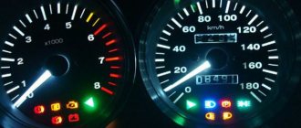
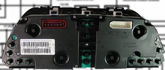
Pinout of the dashboard of VAZ2105, 2106, 2107
Old panel (with oil pressure gauge)
In addition to the presence of an oil pressure indicator, it is worth noting that this instrument panel does not have an air damper indicator lamp (choke), and the emergency oil pressure lamp is located next to the pressure indicator. Because of this, it contains lamps for low brake fluid levels and fog lamps.
- Gasoline level sensor
- Turn signal indicator lamp
- Battery charge sensor (voltmeter -)
- Gasoline level warning lamp
- Overall plus (+)
- Battery charge sensor (voltmeter +)
- Fog lamp warning lamp
- High beam warning lamp
- Dimensions indicator lamp
- Empty
- Battery charge indicator lamp
- Brake fluid level warning lamp
- Empty
- Parking brake warning lamp
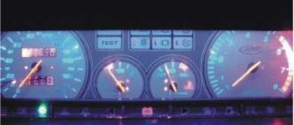
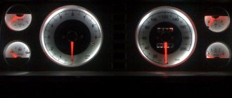
New instrument panel (with econometer)
Here, everything is the other way around - there is no oil pressure indicator (instead there is an econometer), instead of a brake fluid level lamp there is a suction lamp (or an engine management system lamp on injectors), and instead of a fog lamp lamp there is an oil pressure lamp.
- Gasoline level sensor
- Turn signal indicator lamp
- Battery charge sensor (voltmeter -)
- Gasoline level warning lamp
- Overall plus (+)
- Battery charge sensor (voltmeter +)
- Dimensions indicator lamp
- High beam warning lamp
- Oil pressure warning lamp
- Empty, but there is a terminal in the wiring that goes to the brake fluid level sensor
- Battery charge indicator lamp
- Indicator lamp for the air damper (choke) or engine control unit for injectors
- Empty
- Parking brake warning lamp (handbrake)
- General minus (-)
- Tachometer (if this contact is empty, then the tachometer is on pin #4)
- Instrument lighting
- Empty, and if not empty - to the tachometer
- Empty
- Coolant temperature sensor
Second connection diagram option
Instrument lighting of VAZ 2106 does not work ~
Before you know which machine you can install the panel from, you must consider the location and properties of the components that make up its own structure. The left part of the VAZ 2107 torpedo consists of the following parts.
Expert opinion
It-Technology, Electrical power and electronics specialist
Ask questions to the “Specialist for modernization of energy generation systems”
VAZ 2106: instrument panel, its dismantling and installation. It is carefully cleaned, coated with glue. The moment at which the leatherette is attached, the material is smoothed, after which the panel is left for a while so that the glue dries. Ask, I'm in touch!
So the available source materials:
Instrument panel assembled with instruments Fig. 1. (positions 1, 5-9,15-19 are required. Positions 2,3,10 can be taken from 2101, bracket 14 is required when installing console 2106)
Figure 1 – Instrument panel
In Figure 2, in the “glove compartment” section, element 2101-5303015 is shown as the side of the glove compartment, which in fact does not correspond to reality (probably a typo in the book), because panel 2106 in cross-section has a different configuration - you can try to find the part on the market or cut out of plastic according to location.
Figure 2 – catalog numbers
The next necessary spare part is the wiring harness for devices 2106 - Figure 3 - 2106-3724030.
Figure 3 – Wiring harness and instruments
When I asked for a harness on the market, they offered me an “adapter from 2101 to 2106”, upon detailed study it turned out that the difference from those shown in the diagram is that the “adapter” does not have an output to the handbrake lamp relay (2101-3803150), because . on the 2101 relay it hangs on the wires entering the cabin. That is, you can take the standard 2106 harness without any hesitation and move the relay.
Although on the new 2106 circuits there is no relay on the handbrake at all, in this case the “adapter” can essentially just be a harness from the electrical equipment 2106 of the new model.
Limit switch for suction – Fig. 3 – 2101-3803130
Choke, or its handle with a protrusion for the switch - Fig. 4 - 2103-1108100
To connect to the 2106 wiring harness, you need an empty 8-pin connector (female)
DIY instrument panel lighting for VAZ 2106
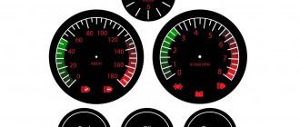
- coolant temperature gauge.
- tachometer;
- left turn signal indicator lamp;
- right turn signal indicator lamp;
- speedometer;
- fuel level indicator;
- fuel reserve warning lamp;
- side light indicator lamp;
- service brake system warning lamp;
- high beam indicator lamp;
- reset button;
- mileage indicator;
- warning lamp for turning on the hazard warning lights;
- "check engine" warning light;
- time and temperature indicator;
- battery charge indicator lamp or battery lamp;
- parking brake warning lamp;
- oil pressure warning lamp;
- reserve.
Pinout of the dashboard of VAZ2110, 2111, 2112
There are 26 contacts on the VAZ-2114 instrument panel, each of which is responsible for the operation of the indicators of this panel. If a plus is supplied to the panel, then each contact displays information about the state in which the car is currently located.
- Housing (weight) - black
- To ambient temperature sensor - cyan-magenta
- Tachometer (low voltage input from ECU) - brown/purple
- Fuse F16 (to terminal 15 of the ignition switch) - orange
- Tachometer (high voltage input from coil) - yellow
- Housing (weight) - black
- To fuse F3 of the mounting block (+battery) - white-purple
- Instrument lighting control - white
- Coolant temperature sensor. - green-white
- Turn signal RIGHT - blue
- To fuse F10 of the mounting block - brown
- Turn signal LEFT - blue-black
- Brake fluid level - pink-blue
- Check Engine Light to ECU Controller - White-Purple
- To the trip computer - brown
- To the ECU controller - pink and black
- Speed sensor - gray and yellow
- To the fuel gauge sensor - orange
- To the fuel gauge sensor - pink
- To the parking brake switch - brown-blue
- Fuse F14 of the mounting block - green-black
- Alternator terminal "D" through fuse panel - brown and white
- Hazard switch
- Oil pressure sensor - blue
- To terminal “50” of the ignition switch - purple
VAZ 2114 instrument panel connection diagram
- rear window heating switch;
- rear fog lamp switch;
- switch for headlights and direction indicators;
- mounting block;
- wiper switch;
- fog light switch;
- on-board control system display unit;
- instrument panel harness block to additional harness;
- instrument cluster;
- instrument panel harness connector to the on-board computer harness;
- instrument panel harness connector to the ignition system harness;
- instrument panel harness connector to the side door harness;
- fuse 16 A;
- fuse 16 A;
- ignition switch;
- lighting switch;
- heater electric motor;
- additional resistance of the heater electric motor;
- ignition switch unloading relay;
- rear fog light relay;
- starter relay;
- socket for connecting a portable lamp;
- cigarette lighter;
- instrument panel harness connector to the glove compartment lamp wiring harness;
- illuminator;
- illuminator;
- illuminator;
- heater switch;
- instrument lighting regulator with rheostat;
- brake light switch;
- horn switch;
- hazard switch;
- heater control lamp;
- fuse 16 A;
- seat heating relay;
Features of electrical wiring of “classic” models
The main characteristics of the VAZ 2106 wiring diagram are the following:
- activation of electrical circuits directly through the ignition switch;
- connection to the battery using the fuse box;
- conductive housings of key components.
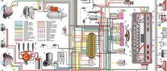
Color factory diagram (1900x1500) of electrical components.
Thus, in the event of a failure of any system, it is advisable to look for faults directly from the ignition switch and contact group.
The role of this node is as follows:
- controls the vehicle ignition system;
- plays anti-theft, including security functions;
- allows you to tow a faulty car with the hazard lights on.
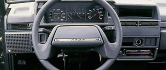
How to replace the instrument panel on a VAZ 2103, VAZ 2106?
Note! Replacing the panel in most cases is not replaced, but only removed in order to replace devices and switches, so if you want to replace only devices or switches, then use the special article on replacement, entitled: “Replacing panel devices”!
Removal: 1) First, taking a screwdriver in your hands, use it to unscrew the five screws that secure the upper and lower parts of the steering column housing.
Note! The letter “A” in the photo indicates the screw that secures the casing to the steering wheel switch; it also needs to be unscrewed, but only carefully!
2) After removing all the screws, remove the lower and then the upper part of the casing from the steering column.
Note! When removing the casing, do not lose the ignition switch ring, which is indicated by the letter “A” in the photo above!
Helpful advice! You can remove the instrument panel without removing the casing; to do this, use a wrench to unscrew the two nuts that secure the steering column compensator.
When both nuts are unscrewed, the steering column will drop sharply down to prevent this from happening, hold it with your hand when unscrewing the nuts. When your instrument panel is installed, then before you start tightening the compensator mounting nuts back, first check the ease of rotation of the steering wheel, and only then tighten the nuts!
Note! The second nut that secures the compensator is located in exactly the same way but only on the right side!
3) Next, using two flat-head screwdrivers at once, pry up the lower part of the panel in the places where it is attached with brackets to the dashboard. After prying, pull the panel towards you and, as a result, remove it from the car.
Note! In general, to remove the panel, it is best to press the panel fastening brackets through the special holes. If these holes are covered with a facing film, then these holes can be easily found at the place where the film will sag, and after finding it, carefully using an awl, you can remove the film so that it does not cover these holes.
And if you don’t have any holes, then, as described at the beginning of this paragraph, remove the panel, that is, pry it off with screwdrivers at the bottom and pull it towards you and remove it!
4) When the panel is removed, take pliers in your hands and, using them, from the back of the instruments that are installed on the panel (first from the speedometer), unscrew the cable end nut and then disconnect the cable end from the speedometer.
5) Now, for convenience, move the panel towards you, and then use a marker to make a mark on each connector. When the marks are made, disconnect all the connectors from each other and, as a result, completely remove the instrument panel from the car.
Installation: 1) Installation of a new instrument panel occurs in the reverse order of removal.
Note! When you get to the final installation of your new panel, always remember! First install the top part of the panel, and only then click on the bottom part to snap it into place.
Expert opinion
It-Technology, Electrical power and electronics specialist
Ask questions to the “Specialist for modernization of energy generation systems”
VAZ 2106 backlight – Illumination of the VAZ 2106 instrument panel If adjustment does not eliminate wheezing, or if signals 1 and 2 operate intermittently, it is necessary to disassemble them and clean the breaker contacts or remove the relay cover and clean the relay contacts. Ask, I'm in touch!
What is contactless ignition and its advantages
Another interesting option for tuning classic models is installing a contactless ignition type. Definitely, the car only benefits from such an innovation - the engine runs smoother, dips disappear when accelerating the car , and it is much easier to start the engine in cold weather. In addition, there are savings associated with fuel consumption.
The wiring diagram on the VAZ 2106 in this case is almost identical: the main differences are the presence of a pulse sensor and the absence of a distributor. While the engine is running, the sensor creates pulses that enter the transistor switch.
Already with its help, other impulses are generated, characteristic of the primary winding on the coil. With interruption, the secondary winding produces high voltage current. From the distributor contact, current is supplied to the spark plugs in the required sequence.
So, you purchase a non-contact ignition package for a VAZ “classic”, which must match the characteristics of the car’s engine. Next, we will need a wiring diagram for the VAZ 2106.
The following spare parts should be included in the configuration of such an ignition:
- switching unit;
- coil;
- high voltage wiring kit;
- spark plugs - DVRM;
- connecting wires.
Stages of work
To successfully replace the ignition with a contactless one, it is important to adhere to the principles of following the correct work technology. Remove the negative terminal from your battery. Any type of electrical repair should always begin with this action.
This is where the wiring for the VAZ 2106 will come to the rescue:
- We disconnect the wires and the main high-voltage wire from the ignition coil.
- Remove the distributor cover.
Be careful not to damage other wires
- The slider should be placed so as not to disturb its necessary settings.
- The mark on the block is placed where there are slots at the bottom of the distributor body.
- Unscrew the nut and take out the old distributor of the previous contact ignition system.
- Before installing the new system, open the cover of the updated distributor and place the slider in the same position as on the old distributor. You can put it in the hole in the block head.
- Move the mark to the required level and tighten the nuts.
Now you can assemble, as the VAZ 21063 wiring diagram suggests - put on the cover, connect the high-voltage wires. You can begin to dismantle the old ignition coil (this was discussed above).
- We install a new coil and connect another outlet of the high-voltage wire to it.
- Now we put all the high-voltage wires in their places. We will need pin “K” for the brown wires of the new coil, while the blue wires will go to pin “B”.
- You need to choose a place to place the switch, most often this is done in the area of the washer reservoir. It is secured with self-tapping screws.
The VAZ 2106 wiring has been replaced, you can tighten the wires with electrical tape. All that remains is to start the engine and adjust the operation of the ignition system.
Note! If the engine of your “six” begins to work intermittently and intermittently, and this is also accompanied by a loss of power, then the cause could easily be misfires.
The first thing you should pay attention to in this case is the integrity of the wiring, including high-voltage, as well as the serviceability of other elements of the ignition system. Spark plugs are checked on a separate stand. In some cases, the cause may be a faulty VAZ 2106 generator and the wiring to it.
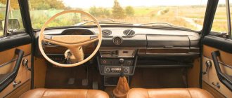
Which foreign car is suitable for a torpedo on a VAZ 2106?
- Instead of the old dashboard, install a new, modern one. The result will bring joy to the car owner, but the cost will most likely upset you. Such a procedure for replacing a dashboard on a VAZ will be quite expensive. And the latest generation dashboards are not reliable and safe, which characterizes old factory torpedoes.
- Puttying and painting. This is an interesting option for improving the instrument panel, but the result is unlikely to last long. After a certain period of time, all painting work will have to be done again.
- Dashboard upholstery with artificial leather. Not every driver will be able to perform this operation beautifully and competently. Craftsmen who do it well will charge a lot.
Instrument panel VAZ 2106 - removal and installation of the instrument panel
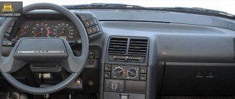
Instrument panel installed on a VAZ 2106 car: 1 - instrument panel (panel); 2 - deflector; 3 — clock; 4 — glove box cover; 5 — radio panel.
1. Remove the storage shelf by removing the four fastening screws.
2. Unscrew the screw of the lower fastening of the radio panel on the left and...
3... screw for the lower fastening of the radio panel on the right.
4. Remove the screw from the top right fastening of the radio panel.
5. Using a screwdriver, remove the mounting plate with additional controls from the radio panel.
6. Remove the two radio panel mounting screws located under the mounting plate.
7. Lift the mounting plate with additional controls and remove the radio panel.
8. Remove three screws and remove the rack cover. Removing the second cover is done in the same way.
9. Remove the decorative lining of the steering column by removing the five fastening screws.
10. Using two screwdrivers, pry the instrument panel fastening plates at the installation locations and remove the instrument panel.
11. Unscrew the nut securing the cable to the speedometer, disconnect the cable and move it to the side.
12. Label the connectors of the wires coming from the instrument panel and disconnect the wire connectors. 13. Remove the instrument panel from the VAZ 2106 car.
15. Label the ends of the wires, disconnect them from the clock and remove the backlight. 16. Take off your watch.
17. Use a screwdriver to pry the heater switch (operating mode switch) and remove it from the ashtray facing panel and heater control levers.
18. Label the wire ends, disconnect them from the switch and remove the switch.
19. Use a screwdriver to release the latches of the heater control handles and remove the handles.
20. Disconnect the wire lug from the glove compartment light socket.
21. Remove the two screws securing the side of the glove box and remove it.
22. Remove the four screws that secure the instrument panel to the body.
23. Unscrew the two nuts of the upper fastening of the instrument panel, located in the glove box, and...
25. Lifting the panel up and towards you, disconnect the tip of the “mass” wire from the glove box light switch. 26. Remove the instrument panel from the VAZ 2106 car, pushing it up and towards you. 27. Install the instrument panel in the reverse order of removal.
So, everything seems to have been pulled together, now let’s get to work:
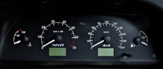
We remove the standard tidy along with the steering wheel. Removing the instrument panel 2101 is described in detail in the manual for 2101. The steering wheel can not be removed, but then the inconvenience during operation greatly increases.
We try on the dashboard to the seats on the body. The differences in the 2101 and –06 devices immediately become visible:
We begin to eliminate the listed interference:
Installation of both stove levers and places for mismatched fastening (Fig. 6)
The heater valve cable is short. Looking carefully at the end of the cable that fits onto the heater valve lever, we see that it is twisted into a ring 3 times - this is the necessary reserve. Unwind the ring - leaving 1 turn (Figure
The cables are sorted out. Now let's figure out where to place the offset fasteners!
We make a U-shaped bracket (Fig. 9)
Figure 9 – bracket for fastening
And we weld it to the intended place for fastening the dashboard -06. The result is a picture - Fig. 10
Figure 10 – Displacement of the fastening point
Now let's take care of the suction - we need to make brackets for it and place it approximately in the place of the old suction. The bracket is made according to TheForester's drawing (special thanks!)
Figure 11 – Homemade suction bracket
Figure 12 – Hand-made bracket for suction
We weld this example of crazy hands to the crossbar:
Figure 13 – Welded to the cross member
After welding, do not forget to prime to avoid rusting.
We insert a cable with suction into the manufactured bracket and screw in the end switch.
There is another important point - because. the speedometer in 2106 is shifted to the right than in 2101, then it is necessary to rewind the sidometer cable differently (see Fig. 14), however, due to the fact that the cable 2101 is longer, in the new place its length turns out to be excessive even after installing the panel due to excess radii If the cable bends, the speedometer needle may shake, so I recommend using a cable from 2103, 2106 that has a shorter length.
Figure 14 – location of the speedometer cable
This is where the mechanical part of the installation actually ends and the electrical part begins:
We screw the oil pressure indicator sensor with a tee (Fig. 4) and tighten the wire from the sensor into the passenger compartment, do not forget to put on the boot (2101-3724114 Fig. 4). We tighten the wire from terminal K - the ignition coil into the passenger compartment. We make a connection with the instrument panel harness 2106. The connection diagram when connecting new devices can differ greatly from model to model due to differences in the colors of the on-board network wires, and even the instrument panel harness 2106, so the correct one will be look at your diagram in place and make the appropriate connections.
In short, the decision comes down to a banal reconnection of wires. In 2101 there are 2 connectors of 6 contacts on the left and right, in 2106 - the left connector has 8 contacts, and the right one also has 6, like 2101.
Payment via PayPal
After selecting payment via PayPal, the PayPal payment system will launch, where you need to select the payment method: bank card or PayPal account.
If you already have a PayPal account, then you need to log into it and make a payment.
If you do not have a PayPal account and you want to pay using a bank card via PayPal, you need to click on the “Create an Account” button - shown with an arrow in the picture.
PayPal will then prompt you to select your country and provide your credit card information.
After specifying the information required to make the payment, you must click on the “Pay Now” button.
Official website of the PayPal payment system https://www.paypal.com
Expert opinion
It-Technology, Electrical power and electronics specialist
Ask questions to the “Specialist for modernization of energy generation systems”
What spare parts are suitable for BMW E30 for VAZ 2107 2106? And the latest generation dashboards are not reliable and safe, which characterizes old factory torpedoes. Ask, I'm in touch!
VAZ 2101 Coupe based on BMW E46
- Using a pencil on the plywood, we mark out the elements of the dashboard, the locations for the instrument scales, and then cut out the individual panel elements. Do not forget about the stove faucet, the place for which must be beautifully cut out;
- We take and adjust a small wooden block to the location for installation in the factory version of the panel. After that, we place it between the plywood sheets, so that it is integrated into the dashboard and secure it with self-tapping screws to the plywood;
- We cut a place in the plywood for a radio or CD and for the manual transmission knob, as well as for the emergency lights and cigarette lighter;
- After preliminary cutting and fitting of the base of the “six” dashboard, we cover the outer surface of the plywood frame with “liquid nails”, after which we carefully apply carpet-type cladding fabric;
- After final drying, we install this structure in place of the dashboard.