Operation of sensors in VAZ injection and carburetor engines: table of typical parameters
Optimal operation of a car engine depends on many parameters and devices. To ensure normal operation, VAZ engines are equipped with various sensors designed to perform different functions. What you need to know about diagnosing and replacing controllers and what are the parameters of sensors for VAZ injection engines is presented in the table in this article.
Typical operating parameters of VAZ injection engines
Checking VAZ sensors is usually carried out when certain problems are detected in the operation of the controllers. For diagnostics, it is advisable to know what malfunctions of VAZ sensors can occur; this will allow you to quickly and correctly check the device and replace it in a timely manner. So, how to check the main VAZ sensors and how to replace them after that - read below.
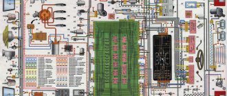
Basic parameters of controllers on VAZ injection engines
Features, diagnostics and replacement of elements of injection systems on VAZ cars
Below we will look at the main controllers!
Hall
There are several options for how you can check the Hall sensor of a VAZ:
The replacement procedure is performed as follows (the process is described using the example of model 2107):
Speeds
The following symptoms may indicate a failure of this regulator:
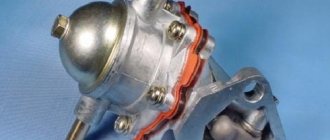
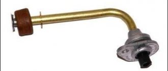
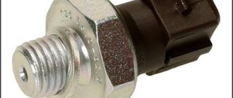
Fuel level
The VAZ or FLS fuel level sensor is used to indicate the remaining volume of gasoline in the fuel tank. Moreover, the fuel level sensor itself is installed in the same housing with the fuel pump. If it malfunctions, the readings on the dashboard may be inaccurate.
The replacement is done like this (using the example of model 2110):
Photo gallery “Changing the FLS with your own hands”
Idle move
If the idle speed sensor on a VAZ fails, this is fraught with the following problems:
To solve the problem of device inoperability, the VAZ idle speed sensor can either be cleaned or replaced. The device itself is located opposite the cable that goes to the gas pedal, in particular, on the throttle valve.
The VAZ idle speed sensor is fixed using several bolts:
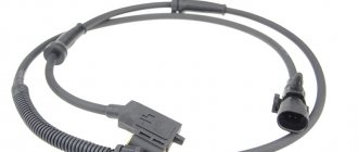
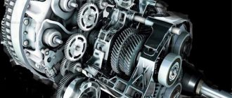
Crankshaft
The VAZ crankshaft sensor is used to synchronize the operation of the fuel supply and ignition systems. Diagnosis of DPKV can be made in several ways.
To replace the DPKV, do the following:
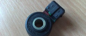
Lambda probe
The VAZ lambda probe is a device whose purpose is to determine the volume of oxygen present in the exhaust gases. This data allows the control unit to correctly create the proportions of air and fuel to form a combustible mixture. The device itself is located on the exhaust pipe of the muffler, at the bottom.
The regulator is replaced as follows:
What happens to a car if the oxygen sensor malfunctions: error codes
Failure of the oxygen sensor on Priora cars and other cars (we are talking about the first lambda probe) leads to the fact that the stable operation of the internal combustion engine is disrupted. In the absence of information from the sensor, the ECU switches the engine to an operating mode called emergency. It continues to function, but only the preparation of fuel assemblies occurs according to average values, which manifests itself in the form of unstable operation of the internal combustion engine, increased fuel consumption, decreased power and increased harmful emissions into the atmosphere.
Typically, the transition to emergency mode of engine operation is accompanied by the illumination of the “Check Engine” indication, which translated from English means “engine check” (and not an error). The causes of sensor malfunction may be the following factors:
- natural wear and tear. Lambda probes have a certain resource, which depends on various factors. Prioras are equipped from the factory with conventional narrow-band zirconium sensors, the service life of which does not exceed 80 km (this does not mean that the product needs to be changed after such a mileage);
- mechanical damage - the products are installed on the exhaust pipe, and if the first sensor is practically deprived of contact with various obstacles that can affect it while driving, then the second is very exposed to them in the absence of engine protection. Electrical contacts are often damaged, which contributes to the transmission of incorrect data to the ECU;
- violation of the seal of the housing. This usually happens when using non-original products. In the event of such a breakdown, the ECU may fail, since an excess amount of oxygen contributes to the supply of a negative signal to the unit, which in turn is simply not designed for this. That is why it is not recommended to choose cheap non-original analogues of lambda probes produced by unknown people class=”aligncenter” width=”800″ height=”545″[/img]
- use of low-quality fuel, oil, etc. If the exhaust is characterized by the presence of black smoke, then carbon deposits form on the sensor, which leads to its unstable and incorrect operation. In this case, the problem is solved by cleaning its protective screen.
Typical signs of failure of the oxygen sensor on a Priora are the following:
- The “Check Engine” indicator lights up on the instrument panel.
- Unstable engine operation, both at idle and when driving.
- Increased fuel consumption.
- Increased exhaust toxicity.
- The occurrence of engine trim.
- The appearance of failures.
- Carbon deposits on the spark plug electrodes.
- The corresponding error codes appear on the bookmaker. Below are their codes and the corresponding reasons for their occurrence.
A malfunction of the oxygen sensors can be determined by the presence of the corresponding error codes, which are displayed on the BC screen (if available) or determined by scanning the ELM327.
ELM327
Here is a list of these error codes for the malfunction of the lambda probe (DC - oxygen sensor) on the Priora:
- P0130 - incorrect signal from lambda probe No. 1;
- P0131 - low signal from DC No. 1;
- P0132 - high signal from DC No. 1;
- P0133 - slow response of DC No. 1 to enrichment or depletion of the mixture;
- P0134 - open circuit of DC No. 1;
- P0135 - malfunction of the heater circuit of DC No. 1;
- P0136 - short circuit to ground in DC circuit No. 2;
- P0137 - low signal from DC No. 2;
- P0138 - high signal from DC No. 2;
- P0140 - open circuit of DC No. 2;
- P0141 - malfunction of the DC heater circuit No. 2.
If the above symptoms occur, you should not immediately rush to change the DC on a Priora car. Confirm the reasons for the malfunction of the device using the corresponding errors or by testing it.
Motorhelp.ru engine diagnostics and repair
Typical operating parameters of VAZ injection engines.
1.3 MAF ADC channel in rest mode: 0.996/1.016 V - normal, up to 1.035 V is still acceptable, everything above is already a reason to think about replacing the mass air flow sensor. Injection systems equipped with feedback from an oxygen sensor are able to correct, to some extent, incorrect readings of the mass air flow sensor, but there is a limit to everything, so you should not delay replacing this sensor if it is already worn out.
2. The engine is idling.
2.1 Idle speed. Typically this is 800 - 850 rpm with a fully warmed up engine. The idle speed value depends on the engine temperature and is set in the engine control program.
2.2 Mass air flow. For 8-valve engines, the typical value is 8-10 kg/h, for 16-valve engines - 7-9.5 kg/h with a fully warmed-up engine at idle. For the M73 ECU these values are slightly higher due to a design feature.
2.3 Length of injection time. For phased injection, the typical value is 3.3 - 4.1 ms. For simultaneous – 2.1 – 2.4 ms. Actually, the injection time itself is not as important as its correction.
2.4 Injection time correction factor. Depends on many factors. This is a topic for a separate article, but it’s worth mentioning here that the closer to 1,000 the better. More than 1,000 means the mixture is further enriched, less than 1,000 means it is leaner.
Parameters of ADC sensors VAZ
- Registration
- Entrance
- To the beginning of the forum
- Forum Rules
- Old design
- FAQ
- Search
- Users
Sorry for maybe stupid questions
As I understand it, this is a crimp on the sensor masses, located 20cm from the ECU connector?
And here is the “wire from the ECU to the 3rd contact of the mass air flow sensor”
on the diagnosis and according to the tester (3rd and 5th contacts of the air flow sensor) 0.996
When driving at low throttle, when releasing the gas, driving at idle and when switching, it jerks. It seems like symptoms of a mass air flow sensor.
it's time to clean and stretch the masses
Types of ECU (esud, controller). What kind of ECUs are installed on VAZ?
"January-4", "GM-09"
The very first controllers on SAMARA were January-4, GM - 09. They were installed on the first models before the year 2000. These models were produced both with and without a resonant knock sensor.
The table contains two columns: 1st column – ECU number, second column – brand of “brains”, firmware version, toxicity standard, distinctive features.
VAZ 2113-2115 from 2003 are equipped with the following types of ECUs:
"January 5.1.x"
Interchangeable with “VS (Itelma) 5.1”, “Bosch M1.5.4”
"Bosch M1.5.4"
The following types of hardware implementation are distinguished:
"Bosch MP7.0"
As a rule, this type of controller is released onto the market and installed at the factory in a single volume. Has a standard 55-pin connector. Capable of working with recrossing on other types of ECM.
"Bosch M7.9.7"
These brains began to be part of the car at the end of 2003. This controller has its own connector, which is incompatible with connectors produced before this model. This type of ECU is installed on VAZ with EURO-2 and EURO-3 toxicity standards. This ECM is lighter weight and smaller in size than previous models. There is also a more reliable connector with increased reliability. They include a switch, which will generally increase the reliability of the controller.
This ECU is in no way compatible with previous controllers.
"VS 5.1"
The following types of hardware implementation are distinguished:
"January 7.2."
This type of ECU is made with a different type of wiring (81 pins) and is similar to Boshevsky 7.9.7+. This type of ECU is produced both by Itelma and Avtel. Interchangeable with Bosch M.7.9.7. As for the software, 7.2 is a continuation of January 5th.
This table shows variations of the BOSCH ECU, 7.9.7, January 7.2, Itelma, installed exclusively on the VAZ 2109-2115 with a 1.5L 8kL engine.
| 2111-1411020-80 | BOSCH, 7.9.7, E-2, 1.5 l, 1st ser. version |
| 2111-1411020-80h | BOSCH, 7.9.7, E-2, 1.5 l, tuning version |
| 2111-1411020-80 | BOSCH,7.9.7+, E-2, 1.5 l |
| 2111-1411020-80 | BOSCH,7.9.7+, E-2, 1.5 l |
| 2111-1411020-30 | BOSCH,7.9.7, E-3, 1.5 l, 1-gray. version |
| 2111-1411020-81 | January 7.2, E-2, 1.5 l, 1st version, unsuccessful, replace A203EL36 |
| 2111-1411020-81 | January 7.2, E-2, 1.5 l, 2nd version, unsuccessful, replace A203EL36 |
| 2111-1411020-81 | January 7.2, E-2, 1.5 l, 3rd version |
| 2111-1411020-82 | Itelma, dk, E-2, 1.5 l, 1st version |
| 2111-1411020-82 | Itelma, dk, E-2, 1.5 l, 2nd version |
| 2111-1411020-82 | Itelma, dk, E-2, 1.5 l, 3rd version |
| 2111-1411020-80 h | BOSCH, 7.9.7, without DC, E-2, din, 1.5 l |
| 2111-1411020-81 h | January 7.2, without dc, with, 1.5 l |
| 2111-1411020-82 h | Itelma, without dc, with, 1.5 l |
Below is a table with the same ECUs, but for 1.6l 8kl engines.
| 21114-1411020-30 | BOSCH, 7.9.7, E-2, 1.6 l, 1st gray, (buggy software). |
| 21114-1411020-30 | BOSCH, 7.9.7, E-2, 1.6 l, 2nd gray |
| 21114-1411020-30 | BOSCH, 7.9.7+, E-2, 1.6 l, 1st gray |
| 21114-1411020-30 | BOSCH, 7.9.7+, E-2, 1.6 l, 2nd gray |
| 21114-1411020-20 | BOSCH, 7.9.7+, E-3, 1.6 l, 1st gray |
| 21114-1411020-10 | BOSCH, 7.9.7, E-3, 1.6 l, 1st gray |
| 21114-1411020-40 | BOSCH, 7.9.7, E-4, 1.6 l |
| 21114-1411020-31 | January 7.2, E-2, 1.6 l, 1st series - unsuccessful |
| 21114-1411020-31 | January 7.2, E-2, 1.6 l, 2nd series |
| 21114-1411020-31 | January 7.2, E-2, 1.6 l, 3rd series |
| 21114-1411020-31 | January 7.2+, E-2, 1.6 l, 1st series, new hardware version |
| 21114-1411020-32 | Itelma 7.2, E-2, 1.6 l, 1st series |
| 21114-1411020-32 | Itelma 7.2, E-2, 1.6 l, 2nd series |
| 21114-1411020-32 | Itelma 7.2, E-2, 1.6 l, 3rd series |
| 21114-1411020-32 | Itelma 7.2+, E-2, 1.6 l, 1st series, new hardware version |
| 21114-1411020-30 h | BOSCH, dk, E-2, din, 1.6 l |
| 21114-1411020-31 h | January 7.2, without dc, with, 1.6 l |
"January 5.1"
All types of controllers of their type are built on the same platform and most often have differences in the switching of injectors and the DC heater.
Let's look at the following example of ECU firmware January 5.1: 2112-1411020-41 and 2111-1411020-61. The first version has phased injection and an oxygen sensor, the second version differs only in that it has parallel injection. Conclusion - the difference between the ECU data is only in the firmware, so they can be interchanged.
Wrong name – January 7.3. This is the last type of controller that is currently installed at AvtoVAZ. This type of ECU has been installed since 2007. on a VAZ with EURO-3 toxicity standard.
The manufacturers of this ECU are two Russian companies: Itelma and Avtel. Below, the table shows ECUs for engines with EURO-3 and Euro-4 toxicity standards.
Understanding the oxygen sensor
It is necessary to determine the sensor articles not by the engine model or even by Euro standards, but only by the ECU unit. The number of oxygen sensors can be two or one - it all depends on environmental standards. AvtoVAZ also used two types of sensors - 0 258 005 133, 0 258 006 537 (BOSCH part numbers). The first of them are compatible with BOSCH M1.5.4, MP7.0 and January 5.1 controllers. Newer sensors were connected to the BOSCH M7.9.7 ECU (January 7.2). The two different types of sensors differ even in appearance. The ECU unit in “Dozens of VAZs” is located under a plastic cover. It is located near the front passenger's foot. The red arrow marks the first, that is, the main sensor. The top photo corresponds to engine 21124 (1.6 l). VAZ-21120 engines (1.5 l) could meet the Euro-3 standard, and then an “extended” catalyst was welded behind the main sensor. The second sensor was located behind it, that is, behind the “can”. Let's clarify:
- The Euro-2 standard corresponds to a design with one sensor (main);
- During the transition to Euro-3 standards, a second sensor was added (blue arrow).
By the way, the 24th engine can meet Euro-4 standards.
How to deceive the mass air flow sensor using ECU firmware
The good thing about the previous method is that its implementation does not require complex equipment or painstaking work. If you were able to check the voltage at the output of the flow meter with a multimeter (which means you at least have one), and know how to hold a soldering iron in your hands, installing a resistor in the wire gap will not be difficult. However, the dependence of voltage on air flow mass is nonlinear. And when the throttle valve opens, the error of the signal corrected by the resistor at rest will increase. Accordingly, the fuel-air mixture will not be ideal.
Types of mass air flow sensors, their design features and operating principle
Three types of VU meters are most widespread:
- Wire or thread.
- Film.
- Volumetric.
In the first two, the operating principle is based on obtaining information about the mass of the air flow by measuring its temperature. The latter may involve two accounting options:
- By changing the position of the slider, driven by a special blade, which is affected by the air flow passing through the device.
Considering the presence of rubbing mechanisms, the level of reliability of such structures is quite low. This was the main reason for the refusal of car manufacturers from sensors of this type. For reference, here is a simplified example of the design of a volumetric flow meter. Volumetric air flow sensor device - By counting Karman vortices. They are formed if a laminar air flow washes over an obstacle whose edges are quite sharp. The frequency of the vortices breaking off from them is directly related to the speed of air flow passing through the device.
Vortex sensor design (widely used by Mitsubishi Motors)
Legend:
- A – pressure measurement sensor to record the passage of the vortex. That is, the frequency of pressure and vortex formation will be the same, which makes it possible to measure the flow of the air mixture. At the output, using an ADC, the analog signal is converted to digital and transmitted to the ECU.
- B - special tubes that form an air flow similar in properties to laminar.
- C – bypass air ducts.
- D – column with sharp edges on which Karman vortices are formed.
- E – holes used to measure pressure.
- F – direction of air flow.
ADC codes
ADC code parameters relate to analog sensors of the control system:
Physically, ADC codes reflect the voltage that the sensor produces. Typically, these parameters are used to test sensor circuits. If fault codes occur associated with a low or high signal level of such a sensor, then the control system operates in backup modes. In this case, the value of the parameter related to this sensor is selected either from the emergency table or calculated using specified formulas, for example, the coolant temperature with a faulty temperature sensor increases during engine operation.
If, during a physical change in the parameter measured by the sensor, the ADC code remains a constant value, then the electrical circuit connecting the sensor is inoperative.
How to properly check the oxygen sensor for serviceability of the Priora: instructions
If there is a suspicion that the lambda probe itself is faulty, and not its circuit, then it is not recommended to rush to change it without first checking it. The check is performed as follows:
- On the DC installed on the car, you need to disconnect its connector. This should change the sound of the engine. The engine should go into emergency mode, which is a sign that the sensor is working. If this does not happen, it means that the motor is already operating in emergency mode, and the DC is 100% certain to be unusable. However, if when the sensor is disconnected, the motor goes into emergency mode, this is not a guarantee of complete serviceability of the product.
- Switch the tester to voltage measurement mode (minimum up to 1V).
- Connect the tester probes to the following contacts: the red probe to the contact of the black wire of the DC (it is responsible for the signal that goes to the ECU), and the black probe of the multimeter to the contact of the gray wire.
- Below is shown the pinout of the lambda probe on the Priora, and which contacts to connect the multimeter to.
- Next you need to look at the readings of the device. As the engine warms up, they should change from 0.9V and drop to 0.05V. On a cold motor, the output voltage values vary from 0.3 to 0.6V. If the values do not change, this indicates a malfunction of the lambda. The device should be replaced. Despite the fact that the device has a built-in heating element, after starting a cold engine, readings should be taken and the correct operation of the element should be determined only after it has warmed up (about 5 minutes).
However, it is possible that the heating element in the sensor could have failed. In this case, the device will also not work correctly. To check the health of the heating element, you will need to check its resistance. The multimeter is switched to resistance measurement mode, and its probes need to be touched to the other two terminals (red and blue wires). The resistance should be 5-10 Ohms, which indicates that the heating element is working properly.
Important! The colors of the wires on sensors from different manufacturers may differ, so you should focus on the pinout of the plug.
Based on simple measures, one can judge the suitability of the recreation center.
Interesting! If there is a suspicion that the DC is faulty, then after the verification procedure it must be dismantled and the working part cleaned. After this, repeat the measurements.
If the lambda probe on the Priora is working, then it would not be superfluous to check the serviceability of the circuit. The power supply of the heater is checked with a multimeter by measuring the voltage at the contacts of the plug to which the device is connected. Checking the signal circuit is carried out by checking the wiring. To help with this, schematic diagrams of wiring are presented to help.
Diagram for oxygen sensor No. 1
Diagram for oxygen sensor No. 2
A faulty sensor must be replaced. Testing both sensors is identical. Below is a description of the operating principle of the devices from the manual for Priora cars.
Description UDC Priora
Description of DDK Priora
It is important to understand that when checking the lambda by output voltage, low readings indicate an excess of oxygen, that is, a lean mixture is supplied to the cylinders. If the readings are high, then the fuel assembly is enriched and there is no oxygen in it. When starting a cold engine, there is no signal from the DC due to the high value of internal resistance.
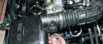
Replacing the air flow sensor
To replace the sensor with your own hands, you need to prepare a shaped screwdriver and a “10” key.
The replacement procedure consists of the following steps:
Disconnecting the sensor connector
Thus, if the car stalls and has all the signs of a breakdown of the mass air flow sensor, then before you start repairing it, you should check the level of its signal, it should not be low, perform a full diagnosis of the car and repair all faulty components and parts.
It is important to undergo regular vehicle inspections and perform timely maintenance, then the parts and components will last longer.
Description of ADS1115 registers
The ADC has only 4 internal registers, all registers are 16-bit, respectively, for each write/read session, 2 information bytes are transmitted via the I2C interface (except for the register address byte). The registers are described in the table below:
| Address | Name | Register description |
| 0x00 | Conversion register | Conversion result storage register |
| 0x01 | Config register | Configuration register |
| 0x02 | Lo_thresh register | Setpoint register, minimum value |
| 0x03 | Hi_thresh register | Setpoint register, maximum value |
The configuration register is used to control the ADC; the register is described in the table below:
| Bit | Bit name | Bit value | Description |
| 15 | OS. The bit defines the state of the device and can only be written in low power mode | For recording | |
| No effect | |||
| 1 | Start conversion, for single conversion mode (low consumption) | ||
| For reading | |||
| Conversion in progress | |||
| 1 | Conversion complete | ||
| 14-12 | MUX. Multiplexer setup | 000 | AINp=AIN0 and AINn=AIN1 (default) |
| 001 | AINp=AIN0 and AINn=AIN3 | ||
| 010 | AINp=AIN1 and AINn=AIN3 | ||
| 011 | AINp=AIN2 and AINn=AIN3 | ||
| 100 | AINp=AIN0 and AINn=GND | ||
| 101 | AINp=AIN1 and AINn=GND | ||
| 110 | AINp=AIN2 and AINn=GND | ||
| 111 | AINp=AIN3 and AINn=GND | ||
| 11-9 | P.G.A. Amplifier Gain | 000 | FS=±6.144 V |
| 001 | FS=±4.096 V | ||
| 010 | FS=±2.048 V (default) | ||
| 011 | FS=±1.024 V | ||
| 100 | FS=±0.512 V | ||
| 101 | FS =±0.256 V | ||
| 110 | FS =±0.256 V | ||
| 111 | FS =±0.256 V | ||
| 8 | MODE. Operating mode | Continuous transformation | |
| 1 | Single conversion, low consumption mode (default) | ||
| 7-5 | D.R. Sampling frequency | 000 | 8 Hz |
| 001 | 16 Hz | ||
| 010 | 32 Hz | ||
| 011 | 64 Hz | ||
| 100 | 128 Hz (default) | ||
| 101 | 250 Hz | ||
| 110 | 475 Hz | ||
| 111 | 860 Hz | ||
| 4 | COMP_MODE. Comparator type | Comparator with hysteresis (default) | |
| 1 | Comparator without hysteresis | ||
| 3 | COMP_POL. Comparator polarity | Low active level (default) | |
| 1 | High active level | ||
| 2 | COMP_LAT. Comparator mode | Comparator without latch (default) | |
| 1 | Latch Comparator | ||
| 1-0 | COMP_QUE. Comparator control | 00 | Setting the output signal after one conversion |
| 01 | Setting the output signal after two conversions | ||
| 10 | Setting the output signal after four conversions | ||
| 11 | Comparator disabled (default) |
Typical parameters of the BOSCH injection system M7.9.7/January 7.2
ECM 2111 – 1411020–80/81/82, 21114 (21124) ‑1411020 – 30/31/32
| Parameter | Name | Unit/composition | Ignition | (XX 800 rpm) | XX (3000 rpm) |
| TMOT | Coolant temperature | °C | (1) | 90° – 105° | 90° – 105° |
| TANS | Intake air temperature | °C | (1) | –20°…+50° | –20°…+50° |
| UB | On-board voltage | IN | 11,8 – 12,5 | 13,2 – 14,6 | 13,2 – 14,6 |
| WDKWA | Throttle position | % | 0 | 0 | 2 – 6 |
| NMOT | Knee rotation frequency. shaft | rpm-1 | (1) | 800 ±40 | 3000 |
| M.L. | Mass air flow | kg/hour | (1) | 7 – 12* 8 – 13 | 24 – 30* 26 – 34 |
| ZWOUT | Ignition timing | grd. p.k.v. | (1) | 7 – 17 | 22 – 30 |
| R.L. | Load parameter | % | (1) | 18 – 24 | 14 – 18 |
| FHO | Altitude adaptation factor | (1) | 0,7 – 1,03** | 0,7 – 1,03** | |
| T.I. | Injection pulse duration | msec | (1) | 3,5 – 4,3 | 3,2 – 4,0 |
| MOMPOS | Current position of the IAC | step | (1) | 40 ±15 | 90 ±15 |
| DMDVAD | XX adjustment adaptation parameter | % | (1) | ±5 | ±5 |
| USVK | Oxygen sensor signal | IN | 0,45 | 0,05 – 0,9 | 0,05 – 0,9 |
| FR | Injection time correction coefficient based on DC signal | (1) | 1 ±0,2 | 1 ±0,2 | |
| TATEOUT | Canister purge signal fill factor | % | (1) | 0 – 15 | 90 – 100 |
| LUMS | Uneven rotation of the knees. shaft | r/sec^2 | (1) | 0…5 | 0…10 |
| FZABG | Counter of misfires affecting toxicity | (1) | 0 | 0 | |
| VSKS | Instant fuel consumption | l/hour | (1) | (1) | (1) |
| FRA | Multiplicative component of self-learning correction | 1 ±0,2 | 1 ±0,2** | 1 ±0,2** | |
| RKAT | Additive component of self-learning correction | % | (1) | ±5 | ±5 |
| B_LL | Sign of engine operation in XX mode | NOT REALLY | NO | YES | NO |
| B_KR | Knock control active | NOT REALLY | (1) | YES | YES |
| B_LR | Sign of engine operation in the control zone based on the DC signal | NOT REALLY | (1) | YES | YES |
| B_LUSTOP | Misfire detection suspended | NOT REALLY | (1) | NO | NO |
(1) – The parameter value for system diagnostics is not used * – The parameter value for ECM 2111 is 1411020–80/81/82 ** – When the battery terminal is removed, these parameters take on fixed values (FHO=0.97 – 0.98, FRA =1)
NOTE: The table shows parameter values for positive ambient temperatures.
Source: VAZ Information Letter No. 1 – 2005‑I
Let's compare architectures
At the moment, there are many different ADC architectures in the world. Each of them has its own advantages and disadvantages. There is no architecture that would achieve the maximum values of all the parameters described above. Let's analyze what maximum speed and resolution parameters the companies producing ADCs were able to achieve. We will also evaluate the advantages and disadvantages of each architecture (you can read more about the various architectures in the article on Habr). Architecture comparison table
| Architecture type | Advantages | Flaws | Maximum resolution | Maximum sampling rate |
| flash | Fast converter. The conversion is carried out in one clock cycle. | High power consumption. Limited resolution. Requires a large crystal area (comparators). It is difficult to coordinate a large number of elements (as a result, low yield). | 14 bit 128 kSa/s AD679 | 3 bit 26 GS/s HMCAD5831 |
| folding-interpolated | Fast converter. The conversion is carried out in one clock cycle. Requires fewer comparators due to preliminary “convolution” of the entire processing range into a narrower range. Occupies less space. | Errors associated with the nonlinearity of the convolution block. Delay for establishing levels in the convolution block, which reduces the maximum fs. Medium resolution. | 12 bit 6.4 GS/s ADC12DL3200 | 12 bit 6.4 GS/s ADC12DL3200 |
| SAR | High accuracy. Low power consumption. Easy to use. | Limited speed. | 32 bit 1 MSa/s LTC2500 | 10 bit 40 MSa/s XRD64L43 |
| pipeline | Fast converter. Highest accuracy among fast ADCs. Doesn't take up a large area. Has lower consumption among similar fast converters. | Pipeline delay. | 24 bit 192 kSa/s AK5386 | 12 bit 10.25 GS/s AD9213 |
| dual-slope | Average conversion accuracy. Simplicity of design. Low consumption. Resistance to changes in environmental factors. | Processes low frequency Signals (low fs). Mediocre resolution. | 12+sign bit 10 S/s TC7109 | 5+sign bits 200 kSa/s HI3-7159 |
| ∑-Δ | The highest conversion accuracy thanks to the “Noise shaping” effect (specific filtering of quantization noise) and oversampling. | Cannot work with wideband signal. | 32 bits 769 kSa/s AK5554 | 12 bit 200MS/s ADRV9009 |
Basket
If Combiloader “does something wrong” or does not do what you think it should do, or does it incorrectly, you need to contact technical support at
This is easy to do if you back up “I can’t”, “it doesn’t work” or “doesn’t want” with a diagnostic log.
How to get it? Just!
1) Download the PortMon program 2) Launch PortMon. It may matter which folder it is launched from. You must NOT receive the message “Unable to load driver.” at startup. 3) Edit-Max output bytes set to 1024 -> Apply. 4) Edit-History depth -> 0 -> Apply 5) Computer -> Disconnect 6) Computer -> Connect local 7) Options -> ShowTime and ShowHex only. Capture -> Capture Events checkbox. 9) Capture -> Ports -> Check the box next to the host/Loader port. 10) Minimize (not close) PortMon. 11) Run the diagnostic program/Bootloader. 12) Reproduce the steps that lead to the error. 13) Close the diagnostic program/Bootloader. 14) Return to PortMon. 15) File -> Save As -> enter the file name and send it to me zipped.
(Points 3 - 9 must be done once, they will be remembered, point 9 may have to be monitored)
If differences with other programs were noticed, do the same with them.
ATTENTION! After starting PortMon, there is no need to remove the host. If you remove it, it will be able to “appear” in the system only after a reboot.
Terms of refund for goods sold
In accordance with the current legislation of the Russian Federation (Law on the Protection of Consumer Rights), the buyer has the right to refuse the ordered goods at any time BEFORE receiving the goods.
The acquisition of the right to use a computer program (license) on the basis of a license agreement is regulated by the norms of the Civil Code of the Russian Federation. Unilateral refusal of the acquired right of use (at the user’s initiative) is not provided for by law, and therefore previously purchased licenses are not subject to return and no refunds are made for them.
Refunds are made only if the electronic key for the computer program copy has not been activated and there is confirmation from the copyright holder.
Term: ADC
Analog-to-digital converter (ADC) is a device that converts an input analog signal into a digital signal (digital binary code). For tasks of measuring the value of a signal at an arbitrary point in time, an asynchronous mode of operation with an ADC with single analog-to-digital conversions that are not strictly time-bound is used. For tasks of measuring the functional dependence of changes in an analog signal, the synchronous operating mode of the ADC is used. The synchronous mode of operation of the ADC without missing data over an arbitrarily large time interval is also called streaming mode. Synchronous ADCs, as a rule, support the frame-by-frame principle of data acquisition, when digitized measurement reports form conditional frames with a specified number of samples corresponding to specified measurement channels.
The ADC is an integral part of the data acquisition system.
Main parameters of the ADC: