For stable operation of the engine, many different parameters are necessary: from fuel quality to valve permeability. However, the error-free operation of the exhaust system can be called one of the main guarantees of normal engine operation.
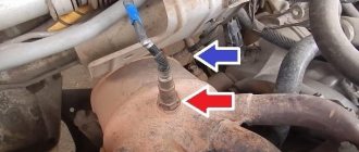
In the exhaust gas system, a catalyst plays an important role, which is designed to purify exhaust substances before they are released into the atmosphere. At the junction between the catalyst and the exhaust manifold there is a special device - an oxygen sensor (otherwise called a lambda probe). And after the catalyst (already at the outlet), a second oxygen sensor is installed, which checks the quality of gas purification and compares the toxicity level with the readings of the first device.
The occurrence of error p0134 on the dashboard can be regarded as a failure of the lambda probe or as a breakdown in the car’s exhaust cleaning system. Accordingly, the uninterrupted operation of the power unit may be disrupted, which can lead to serious financial investments for the owner.
What is this error
Car owners need to know that error p0134 is quite common. Its appearance on the instrument panel in the cabin indicates that the connection with the first oxygen sensor has been lost or the transmitted information is incorrect.
Error p0134 is recorded as follows:
- Data that the signal from the lambda probe is weak or completely absent is transmitted to the memory of the car’s on-board computer and recorded.
- If this data does not change within 60 seconds (that is, the signal remains extremely weak or absent), then the information is sent to the ECU.
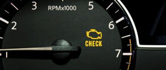
- 5-10 seconds after information is supplied to the control unit, the Check Engine light turns on on the instrument panel in the cabin.
This is the error indicator
When checking with a scanner, the message “P0134 Oxygen O2 Sensor Circuit No Activity Detected (Bank 1 Sensor 1)” is displayed.
Description of the oxygen sensor
DMRV sensor VAZ-2112 16 valves signs of malfunction: check
Let's start with a description of the device. We invite you to familiarize yourself with its purpose, structure, and operating principle.
Purpose and location
The VAZ 2110 lambda probe largely influences the stable functioning of the engine, ensuring the normal operation of its parameters. This controller is an electronic device used to determine the amount of oxygen present in the exhaust gases. This is necessary in order to reduce the volume of harmful impurities and elements contained in exhaust gases. In order to ensure the required proportion of the air-fuel mixture, which affects the reduction in the concentration of impurities, air must be supplied to the engine in the required quantity.
Lambda probe installation location
This is not always achieved, and the reasons may be different. If the controller fails, the carbon monoxide content in the exhaust gases will be about 3-7%, while the standard value is 0.3%. As for the location, this sensor on a VAZ is installed on the exhaust pipe of the muffler, from below. The readings recorded by the lambda probe are transmitted to the motor control unit. And the ECU, focusing on them, adjusts the composition of the combustible mixture, thus setting the required time for the injection phase.
Design and principle of operation
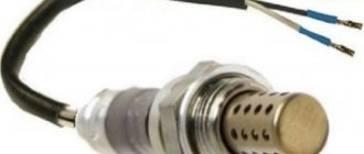
The VAZ 2110 oxygen sensor consists of the following elements:
- steel body;
- insulator component, which is made from ceramics;
- O-ring with wiring and cuffs;
- a special case with holes for ventilation;
- ceramic tip;
- conductive contact;
- a special shield, which also has holes through which gases are released;
- filament coil.
The device is based on two electrodes - internal and external, the first is made of zirconium, and the second is made of platinum. The zirconium electrode is in direct contact with the exhaust gases, and the platinum electrode is in contact with the air. The values that the controller receives are based on the potential difference between these elements. To ensure optimal operation of the oxygen controller, the device must be heated to 300-400 degrees (video author - MotorState channel).
The temperature is quite high, it is achieved through the use of a special heating component, which is built into the structure of the lambda probe. When the engine starts, the control unit adjusts the composition of the combustible mixture based on the readings of other controllers, and not just the lambda probe. In particular, we are talking about mass air flow sensor, throttle opening sensor, antifreeze temperature in the system, etc. And the control unit begins to refer to the lambda probe readings only after the device has warmed up to operating temperature.
Kinds
The first “Ten” injection engines used standard oxygen controllers from the manufacturer Bosch. In 2004, when these car models began to be equipped with more modern injection systems, which were called January 7.2, Bosch M7.9.7, the cars began to be equipped with modernized versions of VAZ oxygen regulators. The latest version differs from the earlier one in that it is equipped with a ceramic heating element, thanks to which less electricity consumption is achieved.
But even this allowed the controller to warm up faster. Currently, Bosch produces seven different types of oxygen sensors with different powers - 12 and 18 W. It should be noted that these devices differ from each other, perhaps, in the values of energy consumption and the number of contacts. In all other respects they are identical.
Reasons for error p0134
Unlike other errors in the ECU, code p0134 clearly indicates the original source of the problem - this is the first oxygen sensor of the catalyst. Therefore, the appearance of this error can only mean one thing: some problems have arisen in the lambda probe.
However, there may be several specific reasons for the error:
- breakdown of the oxygen sensor itself (natural wear);
- breaks and damage to the lambda probe wiring;
- presence of rust on the connectors;
- Short circuit in the network.
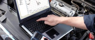
Using professional equipment to diagnose errors helps you quickly and accurately find out the cause of the problem. For example, if the auto scanner produces two errors at once - p0134 and p0171, then this indicates the presence of a short circuit in the network or a wiring break. Accordingly, it is possible to exclude a breakdown of the sensor itself as the cause of the malfunction.
According to existing statistics, in 95% of cases error p0134 appears due to a breakdown of the oxygen sensor itself. And only the remaining 5% of cases occur due to short circuit or insulation damage.
Location and service life of the controller
On a VAZ-2112 with engines with 16 valves, the measuring device is located at the exhaust pipe, between the exhaust manifold and the coupling.
To replace the device, you must gain access to the underbody of the vehicle body. For the best convenience, you need to drive the car into a garage with a pit or drive onto an overpass located near the highway. The service life of the oxygen sensor may vary. If a motorist uses a high-quality fuel mixture, the service life will be up to 110 thousand kilometers. In the case when a low-quality mixture is used, the service life is reduced to 85 thousand kilometers.
How to understand that the oxygen sensor has failed
The car driver can know that the lambda probe has stopped producing a stable signal by several signs:
- the yellow Check Engine light on the dashboard will light up;
- the engine will begin to operate unstably, especially at idle and low speeds;
- Black smoke comes out of the exhaust pipe;
- An unpleasant odor appears in the cabin.
However, in most cases, the very first sign of a bad lambda probe is the Check Engine light coming on. Only in the future, if the car owner has not bothered to eliminate error p0134, may other above-mentioned signs of sensor failure appear.
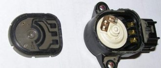
Crankshaft position sensor VAZ 2110
The crankshaft position sensor of the VAZ 2110 injector is quite important, since without it the engine cannot be started. Any malfunction of it brings the “tens” ECU or “brains” of the engine into a stupor. The sensor monitors the position of the camshaft (and therefore the pistons in the cylinders) in real time and allows the spark plugs to work in time. The spark plugs receive a signal from the ignition module that the upper compression point in the cylinder has reached and it’s time to “light” the spark. The sensor itself looks schematically as in this figure -
This is a small electromagnet that picks up the position of a toothed pulley that rotates nearby. The pulley has 58 teeth, which create electromagnetic disturbances. Actually for an injection engine, this is the main and most important sensor.
How does it work
The principle of operation of a lambda probe is to compare the indicators of two electrodes, one of which is located in clean air, and the second in the exhaust manifold.
The VAZ 2110 lambda probe is made of heat-resistant materials, since the exhaust valve system and exhaust system have extremely high temperatures during prolonged engine operation.
The main structural elements of the lambda probe are:
- steel body;
- external platinum electrode;
- internal zirconium electrode;
- ceramic insulator between the inner and outer electrodes;
- electric heater;
- protective casing for the outer electrode.
Also, lambda probes, with some technical differences, have a 4-pin connector:
- 1 contact - signal transmission to the electronic control unit;
- 2 - electrical power;
- 3 and 4 - electrical power supply to the electric heater.
The main task of the lambda probe is to determine the amount of unburned oxygen in the exhaust pipe.
The electronic control unit supplies the electrodes of the lambda probe with a voltage of 0.45 V.
The outer electrode determines the amount of ambient oxygen, the inner electrode determines the amount of oxygen in the exhaust gases. Having received the data, the sensor transmits the corresponding signal to the electronic control unit of the internal combustion engine. The transmitted signal is the difference between two indicators.
The control unit, having processed the received signal, makes adjustments to the operation of all components of the fuel system, and also ignites the combustible mixture earlier or later. This contributes to more stable and smooth engine operation.
On VAZ-2110 cars with 8-valve and 16-valve engines, on which an injector is installed, the sensor is located on the exhaust manifold of the car in front of the resonator.
A special feature of oxygen sensors on VAZ cars is their operating temperature. They begin to function when the temperature reaches 300–400 °C.
In the first minutes after starting the engine, its operation is monitored based on the readings of other sensors: mass air flow and internal combustion engine temperature, as well as the throttle opening sensor.
When the electric heater warms the device to the required temperature, the control unit begins to take into account its readings.
On previously produced VAZ-2110 cars, the manufacturer installed simpler lambda probes, the design of which did not include an electric heater. Consequently, the control unit read its readings only after the engine had sufficiently warmed up. At the same time, before warming up and subsequent monitoring of the operation of the internal combustion engine, the exhaust gases contained a significant amount of harmful elements.
After the approval of new legislation concerning a clean environment and a reduction in air pollution, car manufacturers began to install lambda probes that are able to independently warm up to the required temperature and, after a short period of time, provide less toxic emissions into the atmosphere.
Also, on a certain type of VAZ-2110 engine, the manufacturer installed a system of two lambda probes, which is also located on the exhaust system.
The first is located in front of the catalyst. It determines the quality of the exhaust gases before they enter the catalyst.
The second is after the catalyst, thereby checking the quality of its work, which consists of purifying exhaust gases to the level required by law.
Functionality check
Many VAZ-2112 owners ask how to check the lambda probe (oxygen sensor) themselves. To do this you will need to do the following:
- It is necessary to turn off the engine and allow it to cool.
- After this, open the hood of the car and disconnect all contacts leading to the oxygen sensor.
- Take a multimeter and connect the end probes to the lambda probe.
- Then use the “Resistance” mode on the multimeter. If the arrow goes to infinity, then the device is working correctly and the readings are being transmitted correctly.
- In a situation where the arrow shows a value near zero, the measuring device is faulty and needs to be replaced.
How serious is p0134?
If error P0134 appears, it is unlikely that serious problems will arise with the vehicle's handling, but the error should not be ignored.
If the problem is left unaddressed for a long time, it can cause damage to the catalytic converter. Also, when this error appears, fuel consumption may increase and engine power may drop. If a P0134 code is detected, it is recommended that you contact a qualified technician as soon as possible to diagnose and repair the error.
Signs and causes of lambda probe malfunction
According to statistics, oxygen sensors fail gradually, so you can identify its malfunction if you pay attention to the following “symptoms” in time:
- The idle speed began to drop or “float”.
- The car jerks, and after starting the engine, popping noises uncharacteristic of the engine are heard.
- The engine power has decreased and when you press the gas pedal there is a slow response.
- The engine overheats greatly and fuel consumption has increased.
- The smell in the exhaust pipe has changed (exhaust gases have become more toxic).
As a result of a failed sensor, the quality of the fuel mixture entering the combustion chamber deteriorates, which disrupts the smooth operation of the engine. There can be many reasons for this:
- Incorrect operation of the filament circuit or reduced sensitivity of the sensor tip.
- Low-quality fuel with a high content of iron, lead, oil decay particles and other harmful inclusions. All these substances stick to the platinum electrodes, causing the sensor to malfunction.
- Problems with the lambda probe heating system. If the heating stops functioning as it should, the oxygen sensor will produce inaccurate data.
- Overheating of the regulator housing. This happens if the ignition timing is incorrectly set.
- Worn oil scraper rings. In this case, engine fluid enters the exhaust pipe, which affects the lambda probe.
- If the engine is started repeatedly.
- Using sealants (especially silicone) to install lambda probes.
- The compression level in the engine cylinders is impaired. In this case, the combustible mixture burns unevenly.
- Clogged engine petrol injectors.
If you notice that the lambda probe is not working, you should not ignore the symptoms, as otherwise you will cause yourself a lot of problems with your car. The fact is that most modern cars are equipped with an emergency locking unit, which can work at the most unfortunate moment. However, the impossibility of further movement is not the worst thing. If the sensor becomes depressurized, the injection system will fail and you will have to pay for expensive repairs to a more serious unit.
Therefore, it is recommended to periodically check the condition of the lambda probe. You can do this yourself.
On what cars does it occur?
It cannot be said that error P0134 is a typical problem for a particular automaker or the vehicle models it produces.
But if you look at the statistics of calls to car services when error P0134 was diagnosed, then among the most common cars we can distinguish the following brands and models:
- domestic cars of the VAZ series, including VAZ 2110, 2112, 2114 and 2115;
- newer models under the Lada brand, including Priora, Kalina and Granta;
- Chevrolet cars up to 2022;
- some Mazda models;
- Nissan budget representatives;
- most small cars from Peugeot;
- domestic favorite Lanos;
- previous generations of Hyundai Accent;
- some Opel models;
- Mitsubishi cars, mostly up to 2022, etc.
It is impossible to say that error P0134 will definitely appear on these machines, but not on others. Much depends on the quality of the sensor itself, operating conditions, the condition of the exhaust system, the fuel being poured, the condition of the engine, etc.
Diagnosis of error P0134
If error P0134 still appears and it was possible to read it with a scanner, diagnostic and repair work must be carried out. In most cases, error P0134 can be resolved on your own. But sometimes you have to seek qualified help.
How to troubleshoot P0134?
Before attempting to electrically diagnose the P0134 code, ensure that the engine is running and that there are no air leaks or serious exhaust leaks that could affect the operation of the oxygen sensors.
Also, make sure there are no rich or lean conditions and that the engine oil is not contaminated with antifreeze. If any other codes are present along with P0134, troubleshoot those issues first before attempting to diagnose P0134.
In a properly functioning oxygen sensor, any change in throttle will result in an almost immediate change in signal voltage. However, the speed at which changes occur (depending on the efficiency of the sensor) is best assessed using an oscilloscope.
Keep in mind that while an oscilloscope can identify emerging problems, interpreting the resulting waveforms requires expert knowledge and verified reference data for each vehicle being tested.
Therefore, in order to identify a faulty DC (if there is no oscilloscope), it should be enough that there are no changes in the signal voltage during a discernible period.
Step 1
Take a diagnostic scanner or adapter and read the information from the car. Record all stored trouble codes and available freeze frame data. This data can be useful if an intermittent error is later diagnosed.
Step 2
Visually inspect all wiring associated with the damaged sensor. Look for burnt, shorted, or otherwise damaged wires and connectors. Restore them if required.
Step 3
If there is no visible damage to the wires, check resistance, input (reference) voltage, ground, and continuity in all circuits associated with the damaged sensor.
Before checking the wiring integrity, be sure to disconnect the sensor from the ECU to prevent damage to the controller.
Since the P0134 code indicates a problem in the signal voltage circuit, as opposed to the heater control circuit, pay special attention to the resistance and continuity values in the signal circuit between the ECU connector and the sensor. These values must correspond exactly to those specified in the repair manual.
Try to avoid signal circuit repairs - it is best to always replace the associated harness to avoid problems with poor connections and high resistance that can arise from poorly executed repairs.
Make sure that the sensor is receiving full voltage from the battery. Keep in mind that in some cases the heater circuit voltage comes from the ECU, in which case the circuit is not protected by a fuse. Look in the repair manual to see how voltage is supplied to the DC heater.
Since the sensor has a heated element, it is possible that low battery voltage, poor grounding, or other resistance issues could affect the time it takes for the element to heat up, which is one reason why the code may set. P0134.
It goes without saying that the voltage/condition of the battery should also be checked. However, in cases of low battery voltage, codes related to low input voltages to the heater control circuit may be present along with P0134.
Step 4
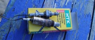
If all data obtained is within the manufacturer's specifications, unscrew the oxygen sensor from the exhaust pipe and inspect it for discoloration or the presence of any type of deposits that may reduce the effectiveness of the sensor. In general, the correct color of the oxygen sensor should be the same color as a healthy, properly functioning spark plug.
Compare the sensor to the pictures at the top of this article, but keep in mind that the DC cannot be cleaned of deposits. The only reliable remedy is to replace the sensor rather than use any additives.
If the DC does not show discoloration or deposits, measure the sensor resistance and replace it if its resistance is outside the manufacturer's specifications.
Replacing the sensor does not make sense if it shows signs of “poisoning” with oil or antifreeze. In these cases, the underlying problem must be resolved to prevent the P0134 code and its associated symptoms from recurring.
Step 5
If you have checked all associated wiring, all electrical parameters specified in the manufacturer's specifications, and replaced the appropriate DC, test the vehicle to ensure the repair was successful. Sometimes a fault code returns. There may be an intermittent (intermittent) error present.
Detecting and correcting intermittent faults can sometimes be very difficult and in extreme cases may require the problem to worsen before an accurate diagnosis and permanent repair of the fault.
Source
Use a gas burner or stove
In this case, we will need a gas stove or burner and the already known phosphoric acid.
POPULAR WITH READERS: How to properly install a child car seat, selection criteria
The device is lowered into the acid for a few seconds and quickly brought to the fire.
Be careful not to expose any plastic covers that may be on the device to high temperatures.
After a certain time (you won’t have to wait long), a light gray salt will appear on the surface of the sensor core as the acid boils.
The acid should completely boil away. Do not allow vapors of the chemical compound to enter your respiratory system.
Remove the lambda probe from the fire, and then repeat the procedure again until the salt no longer appears.
Ho2s circuit weakening sensor 1
Description of the scheme
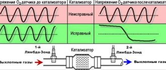
The ECM supplies approximately 0.45 V between terminals M12 and M29 (when measured with a 10-megaohm voltmeter, this value may be 0.32 V). The oxygen sensor before the converter (HO2S1) changes the voltage within 1 V with a saturated exhaust, and within 0.10 with a lean exhaust.
The sensor acts as a circuit breaker and does not produce a signal if its temperature is below 315°C (600°F). An open circuit to the sensor or a cold sensor results in open loop operation.
If the HO2S1 wiring, connector or terminal is damaged, the entire HO2S1 unit must be replaced. Do not repair the wiring, connector or terminals. For proper operation of the sensor, it is necessary to provide it with a reference signal of clean air. This clean air reference is provided by wire(s) HO2S1.
Conditions for Setting the DTC
- The voltage of the HO2S1 sensor is between 420 and 480 mV.
- Engine coolant temperature is more than 60°C (140°F).
- On-board network voltage is more than 10 V.
- Engine operating time is more than 60 seconds.
- Air flow more than 9 g/sec.
- DTCs 0106, 0107, P0108, P0117, P0118, P0122, P0123, P0171, P0172, P0201, P0202, P0203, P0204, P0300, P0336, P0337, P0351, P0352, P0402, P0 404, P0405, P0406, P0506, P0507 , P1404, P0443 are not installed.
- 3-second delay after activating the fuel cut-off mode when braking.
Action Taken When the DTC Sets
- The malfunction indicator lamp lights up.
- The controller records the operating conditions at the time the fault is detected. This information is stored in a status record buffer and fault logs.
- An archive of diagnostic trouble codes is saved.
- The vehicle operates in an open circuit.
Conditions for Clearing DTC/Malfunction Indication
- The MIL turns off after four consecutive ignition cycles in which the diagnostics have not detected a malfunction.
- The DTC history is cleared after 40 consecutive heating cycles without faults.
- The DTC can be cleared by a scan tool.
- The ECM power supply is turned off for more than 10 seconds.
Diagnostic information
- Typical scan tool voltages range from 150 mV to 850 mV when operating in closed loop mode.
Description of the test
The numbers below indicate the operation numbers in the diagnostic table.
- The On-Board Diagnostic (EOBD) system prompts the technician to perform basic checks and store status and fault data in the scan tool. This creates an electronic copy of the data recorded when a fault occurs. The information is stored in the scanning device for further processing.
- When the engine warms up, the HO2S1 sensor should also warm up and its output signal should vary from 150 mV to 850 mV. If the HO2S1 signal changes, the engine enters closed-loop operation. This step determines whether the HO2S1 sensor is working correctly.
- At this point, it is determined whether the sensor is working properly or whether the ECM wiring is causing the P0134 fault code to set.
- Use only a high resistance digital voltmeter to perform this test. When performing this test, the signal circuit and the ground circuit of the HO2S1 sensor are connected. If the ground circuit is open, the ECM voltage will be higher than 0.6 V (600 mV).
- The replacement ECM must be programmed. Reprogramming the ECM is described in the latest Techline.
More about Aveo: Chevrolet Aveo 2014: rim and wheel size, bolt pattern, tire pressure, wheel offset, DIA, PCD, drilling, standard tires and tuning
DTC P0134 – Sensor 1 weakening of HO2S sensor circuit activity