Decoding VAZ 2110 error codes and measures to eliminate them
Many VAZ 2110 car owners, especially those who have no accumulated experience in driving and repairing the “tens”, fall into a slight panic if “CHECK” suddenly lights up on a seemingly serviceable car, and the on-board computer begins to generate an error.
They are usually expressed using the letter P and a numeric four-digit code. Naturally, error codes for the VAZ 2110 are not difficult to find in special tables in order to understand in which system the cause should be looked for. However, the decoding is often very vague, and it is not clear what to do next?
Errors on the VAZ 2110 on-board computer: note to owners of “Ten”
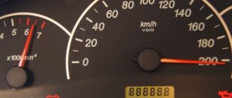
VAZ 2110 error codes are presented numerically on the display, and they are transmitted from phase sensors to the on-board computer. This is convenient, but a novice driver will not understand much and will not be able to figure out how to use this equipment. But you need to know and be able to do this, since the system, thanks to the built-in self-diagnosis function, will help to identify a malfunction in the early stages, which means it is possible to eliminate it in a timely manner.
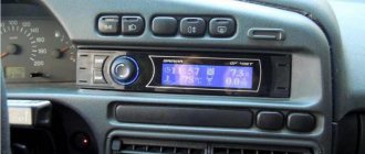
Electronics
Let's look at some especially annoying error codes, which, as if they don’t affect the speed, but constantly remind you that something may be wrong with the VAZ 2110. These include:
- error 1621, warning the driver that the RAM is disabled, that is, code 1621 indicates that the controller is not working, which means that errors are not read, you remain in the dark about what is happening with the systems of your car. Most often, when drivers see the numbers 1621, they ignore them, reset the RAM error (remove the terminal from the battery for a couple of minutes, then put it back on) and drive on. But, after turning off the car and starting it again, they see the same ill-fated code 1621. You can try to carefully inspect the twist near the ECU (to ground), and perhaps additionally solder the factory crimp. However, often even contacting specialists does not help; code 1621 remains on until the RAM memory is changed;
- Sometimes it happens that the injector light comes on. This is especially observed in winter, and when the engine warms up well, the light goes out. Although this is not so scary, it is somewhat unnerving, and the light bulb breaks down if it burns for a long time. It’s better to contact a service center where they can update the firmware, then the light bulb will stop bothering you.
Injector indicator
How to reset the error?
You can delete the error code from the memory of the VAZ control unit by disconnecting the terminal from the battery.
The reset procedure is performed as follows:
- The vehicle's ignition system is activated, but the power unit does not start.
- The engine compartment of the vehicle opens. Using a wrench, loosen the screw that secures the terminal clamp on the negative output of the battery.
- After about one minute the contact is reconnected.
- The engine compartment of the car is closed, the ignition system in the car is turned off.
- The car engine is starting. If the “Check” indicator remains lit on the dashboard, it should disappear on its own after a few kilometers.
Crankshaft and camshaft
- code 0335 indicates a malfunction of the crankshaft position sensor. Therefore, when you see 0335 on the computer, you need to check whether the signal is coming from this sensor. If you find that the signal is weak, you can help by changing the air flow if it is excessive (above the maximum). After this, error 0335 should disappear;
- When you see error 0340, you know that the camshaft position sensor is most likely faulty. Although in fact, even if 0340 is displayed, the camshaft itself may be in good condition, the car is working as usual. But when the numbers 0340 do not disappear while the engine is running, this unit should be carefully inspected.
You can read more about the operation of the crankshaft sensor in this material: https://vazweb.ru/desyatka/dvigatel/datchik-kolenvala.html
Electrical equipment
Malfunctions of the electrical equipment of the VAZ 2110 should be responded to as quickly as possible. By the way, this can be signaled by code 1602, although its decoding sounds like a loss of on-board power supply voltage in the RAM.
Sometimes it is enough to reset error 1602, and it will not appear again. Some people call these numbers “good”; 1602 may appear after the battery is disconnected, due to a voltage surge when starting the engine (for example, in cold weather). However, if 1602 “pops up” constantly, you need to look for a network break.
First, try to clean the battery terminals and secure them well. Did not help? Check the circuit, starting from the “+” of the battery, be sure to check the fuse, fuse link.
Oxidized battery terminals
And also inspect the mass of the ECU, TPS. There are cases when code 1602 appears due to the fact that the security alarm blocks the controller circuit, and it issues this as an error every time. You should contact the installer of your alarm system.
Possible mistakes
VAZ 2110 injector error
Errors can relate to various parts of the car:
- Sensors. Temperature sensors are most often affected.
- Injectors (see VAZ 2110 injectors and cleaning them). Mostly, problems are observed due to an open circuit, as a result of which the injectors cannot light up in time.
- Engine. Engine problems usually appear after driving a car for a long time. The most common mistake is overheating.
- Valves.
- Fans. If they do not work with all their strength, the machine overheats. Therefore, errors of incorrect fan operation lead to errors with engine overheating.
- Relay.
- Controller.
Idling
Code 0505 indicates a malfunction of the idle air control. Moreover, 0505 is most often “issued” when the engine is started with the gas pedal pressed. This often affects drivers who switched from a carburetor VAZ 2110 to an injection one.
However, 0505 also occurs if the ignition module, spark plugs are faulty, there are broken wires, or the engine speed is not the one set by the XX regulator.
Idle speed control
If you notice popping noises in the muffler, this may also indicate displacement of the crankshaft ring gear. Code 0505 can be displayed either alone or with 0300 (missing cylinders).
Throttle valve
The on-board computer issues two unpleasant errors - 0122 and 0123 when there is a problem with the throttle sensor. Moreover, 0122 will be displayed if the signal level of this sensor is low, and 0123 – if it is high.
Both one and the other, naturally, are not good. Especially if the on-board computer readings are accompanied by increased idle speeds, jerks at low speeds and dips. In this case, replacing the sensor does not always help.
Throttle position sensor
If codes 0122, 0123 are issued, be sure to check the signal and power wires for breaks, and also pay attention to whether there is any leakage through the injector rings. Remember: the main enemies of DPZD are engine washing and also the manufacturing plant, since there are a lot of defects here.
The following material is devoted to common malfunctions of the throttle position sensor: https://vazweb.ru/desyatka/pitanie/drosselnaya-zaslonka.html
Oxygen sensor
For some reason, it is quite difficult to find code 0525 in the decoding tables, but this is simply an error in the oxygen sensor, otherwise called a lambda probe. And if you see 0525 on the display again, it means that not everything is in order with the oxygen content in the exhaust.
This sensor is not installed on all VAZ models; it sends a signal to the engine regarding how much oxygen should be in the fuel system. That this sensor does not cope with its duties is evidenced by:
- increased fuel consumption;
- unstable work at XX;
- loss of power, lack of "response".
Lambda probe of the new Bosch model
In principle, the lambda probe should be changed after approximately 60 thousand mileage, but this can happen earlier, especially considering the quality of our gasoline. Therefore, it may display 0525, warning that it is time to replace the oxygen sensor.
Error Diagnosis Methods
In 2022, errors on the VAZ 2110 on-board computer can be identified in two ways.
- Self-diagnosis. The method is feasible thanks to a special option in the on-board computer. The principle is that the system shows faults in the main circuits and mechanisms. The advantage is that there is no need for additional equipment or special programs - everything that is needed is already “hardwired” into the on-board computer. The disadvantages include the low accuracy of the readings.
- With the help of auxiliary equipment. This type of procedure is characterized by high accuracy of the read data. Thanks to a third-party analyzer, you can find out exactly where the breakdown occurred, which simplifies the repair process. An obvious disadvantage is the need to connect a computer with a special program. Such equipment is present only in specialized service stations.
Self-diagnosis VAZ 2110: error codes
To enable self-diagnosis mode, the driver or technician will need to perform a certain sequence of actions.
- Turn off the engine ignition.
- Press the daily mileage reset button and, without releasing it, turn on the ignition. In this case, all digital cells should light up on the display.
- Click on any module control button twice.
- The device will display the error number.
If everything is done correctly, one of the following symbols will light up on the device:
- 2 – critical excess of the rated voltage of the on-board network, a short circuit of the main line or loaded components is possible;
- 3 – a similar error on the instrument panel of the VAZ 2110 indicates that the gasoline level sensor is damaged or there are problems in the sensor’s power supply; to check, you can replace the part with a new one and ring the circuit;
- 4 - error 4 VAZ 2110 indicates that the antifreeze temperature sensor is broken or its wiring is broken, the problem is resolved in the same way;
- 5 – the thermometer designed to measure the temperature outside is faulty;
- 6 – the engine is very overheated, you need to stop and wait for it to cool down, and there should be a sound signal (add antifreeze/water into the radiator);
- 7 – the lubricant pressure in the crankcase compartment of the engine is below the established norm, the losses must be urgently replenished;
- 8 – error 8 VAZ 2110, interpretation shows that the brake system is damaged, possibly a drop in the fluid level in the expansion tank or severe wear of the pads;
- 9 – the battery is completely discharged, the element needs to be charged or replaced with a new module;
- E – software failure of the on-board computer firmware; complete diagnostics with a scanner and qualified repairs in a workshop will help here.
Also, error 14 VAZ 2110 or another two-digit number will indicate the presence of two problems. Usually, with such a picture, the ciphers are summed up. For example, error 10 VAZ 2110 may indicate problems in circuits No. 4 and 6.
How to reset errors on a VAZ 2110
Typically, the procedure is carried out after repairing the unit for which the fault code is responsible. In this case, the symbol does not disappear - it must be forcibly reset. This is done quite simply. The user is required to enter the service mode (hold down the daily mileage button), then double-click on any control. After completing the manipulations, a code will appear on the display. To eliminate this, the daily mileage button is pressed for 3-4 seconds and the system is reset. The machine exits the dialog box automatically after 30 seconds of inactivity.
More about the block
Open doors
This function works thanks to limit switches in the door. When the door is opened, the switch contacts close and the door open lamp lights up. Each limit switch is responsible for the door in which it is installed.
Quite often it happens that due to oxidation of the limit switch contacts, the indication does not operate. This problem is solved by removing the end switch and cleaning its contacts with sandpaper.
Low oil level
A special oil level sensor is installed in the engine crankcase, which informs the driver when the level drops to a minimum value. The sensor is a reed switch with a float; the contacts of the reed switch close when the oil level drops, which leads to the lighting of the corresponding lamp on the display unit.
Low antifreeze level
This indication system is similar to the oil level design. A sensor is installed in the expansion tank, operating on the principle of an oil level sensor. When the coolant level decreases, the contacts on the sensor close and the low antifreeze level indicator lamp lights up.
Low washer fluid level
The principle of operation of this indicator is to measure the windshield washer fluid level. There is a level sensor in the washer reservoir, the same as in the expansion tank. It measures the level and, when the minimum mark is reached, lights the lamp on the display unit.
Front pad wear
This indication informs the driver about the wear of the front pads; this occurs using a sensor that is connected to the pad itself. It is important to note that in order for this indication to work, it is necessary to use special blocks in which this sensor is built-in.
Unfastened seat belt
This function has long been known on cars of foreign origin, but it was used for the first time in AvtoVAZ. The sensor built into the seat belt buckle closes its contacts when the belt clip is inserted into it. If you start driving without a seat belt fastened, the display unit will begin to emit a sound warning of danger.
Burnt out lamp indication
The essence of this function is to inform the driver about one of the burnt-out lamps in the headlights or taillights. This function works by measuring the resistance in the power supply circuit of headlights or flashlights. As soon as the lamp burns out, the power circuit is interrupted, which causes the indicator on the unit to light up.
Forgotten key in the ignition
After stopping the engine and turning off the ignition, if you open the door while the key is inserted into the lock, the display unit will emit a sound signal that will last 10 seconds and will stop if you close the door again or remove the key from the lock.
Diagnostics using a scanner
The method involves connecting an external computer with the program installed. This opens up more opportunities for car diagnostics. In this case, error codes for VAZ 2110 and VAZ 2112 consist of 5 characters.
- P – failure or malfunction of the power plant, transmission;
- B – body systems are damaged;
- C – a problem has been detected in the vehicle’s chassis;
- U – violation of pairing of different modules.
- 0 – general value;
- 1/2 – manufacturer code;
- 3 – reserve.
- 1-2 – violation in the air-fuel mixture supply devices;
- 3 – malfunction of the ignition units;
- 4 – atmospheric emissions control device;
- 5 – malfunction of the engine speed or engine speed meters;
- 6 – failures in electronics;
- 7-8 – malfunction of the gearbox module;
- 9-0 – reserve unit.
The last two digits give the serial number of the breakdown and its location.
Diagnostics
There are two ways to diagnose the condition of car systems. Let's start with the first one, which does not involve the use of additional equipment.
To start the self-diagnosis function, you need to press a button that resets the mileage for the day. Turn on the ignition. You will see how the arrows on the instruments begin to move from one position to another. This means that the diagnostics of the VAZ 2110 has been launched and information has begun to flow from the phase sensors to the ECU. After the process is completed, the RAM will transmit numbers to the display that will show the state of the car’s systems.
VAZ 2110 car
Decoding combinations
When the self-diagnosis is completed and the number 0 is displayed, this means that everything is in order with the vehicle and all systems are working as expected:
- if 1 is displayed, this indicates that there are problems with the microprocessor or the RAM is failing;
- 4 - high voltage in the network, more than 16 V;
- if 8, then low.
If there is not one fault, but several, then a figure equal to the sum of faults will be displayed. If 6 lights up, then this will mean the sum of the numbers 2 and 4. If 14, then most likely there are three malfunctions at once, namely 2, 4 and 8.
The simplest diagnostics that is available to the driver without the use of additional equipment. It will, of course, help identify some faults, as well as show the condition of the components and systems of the VAZ 2110 as a whole. But to specifically identify all faults and decipher information coming from phase sensors, additional tools are needed. For example, the on-board computer STATE, which provides more data.
Daily mileage reset button
Decoding error codes for VAZ 2110
Next, we consider the decoding of VAZ 2110 error codes that occur most frequently. For ease of reading, the information is divided into logical blocks.
Sensor failures
- 0030 – the control controller for the temperature of the air entering the intake manifold is damaged;
- 0032 – a short circuit occurred in the lambda probe lines touching the on-board circuit;
- 0036 – open circuit of the heater sensor installed after the catalyst;
- 0102 – Mass air flow sensor does not respond or is damaged, can also be caused by a malfunction of the flow meter, replacing the air filter may help;
- 0103 – erroneous signal from the mass air flow sensor, the faulty module may need to be replaced;
- 0112-113 – air temperature controller on the intake manifold – a defect has been detected;
- 0116 – DTOZh signal is interrupted or does not arrive evenly, the wiring may be damaged;
- 0117/118 – similar sensor, erroneous/too high signal;
- 0122/123 – TPS has failed or is acting up, the entire circuit will need to be fully diagnosed;
- 0130-132 – problems in the oxygen controller circuits;
- 0133 – slow response from control center 1;
- 0134 – the voltage in the lambda probe circuit has critically decreased;
- 0135 – the oxygen controller heater is damaged;
- 0140 - a similar error on the VAZ 2110 computer indicates a break in the DK2 control circuit;
- 0222 – TPS, open circuit or short circuit;
- 0325 – DD is damaged or the power line is ruptured;
- 0326/0327/0328 – the signal from the knock sensor has exceeded the maximum limit or is too low/line broken;
- 0336-337 – DPKV is broken or the wires are shorted;
- 0340/341 – DPRV is out of order or there is damage to the cables;
- 0342/343/346 – phase distribution sensor failed/control break/short circuit;
- 0500/0501 – the speedometer sensor is broken or shows incorrect data;
- 0504 – the actual position of the brake pedal does not correspond to the calculated indicator;
- 0505/0511 – DXH has failed, the engine speed may fluctuate, you also need to check the lines;
- 0830 – data from the clutch pedal position sensor is incorrectly read;
- 1135 – DK1 is damaged, line diagnostics are required;
- 1141 – the heater of the lambda probe installed in front of the catalyst is faulty;
- 1513/1514 – the XX sensor is damaged or the wires are shorted;
- 1617 – the rough road controller produces a value exceeding the nominal thresholds; it does not affect the operation of the internal combustion engine;
- 2020 – the position dampers of the intake elements do not work correctly;
- 2122/2127 – the gas pedal position sensor gives incorrect signals, the calculated position differs from the actual one;
- 2138 - the same, with a violation of pairing with each other.
VAZ 2110 error numbers for the power plant
- 0101 – Mass air flow sensor gives a false signal, the intake manifold may need to be cleaned;
- 0121 – there is no power supply to injector No. 3, usually the motor is rough;
- 0171 - VAZ 2110 engine error indicates that fuel supply is difficult, probably problems with the pump or filters;
- 0172 – the opposite problem, you should check the air leaks at the fuel line connections;
- 0204 – no voltage at engine injector 4;
- 0300 – multiple misfires detected;
- 0301-304 – similarly for each cylinder in order;
- 0335 – crankshaft desynchronization;
- 0363 – there is a misfire in one of the cylinders, the system has turned off the supply of the combustible mixture;
- 0422 – catalyst clogged;
- 0441/443/444 – the canister purge valve is damaged or there is no power to the element;
- 0485 – the main radiator fan is not working properly;
- 0506/507 – idle speed too low/high;
- 1140 – the actual load on the engine differs from the measured values;
- 1301/2 – gaps in the ignition system of the catalyst protection device;
- 1303/4 – misfire in 3/4 cylinders;
- 1335 – the throttle valve actuator is not working correctly;
- 1426 – canister purge valve, wiring damaged;
- 1545/1578 – throttle valve clogged or broken;
- 1602 - error 1602 VAZ 2110 indicates that a critical voltage drop has been detected in the on-board network;
- 2135 – the throttle device is acting up;
- 2187 - VAZ 2110 injector error says that too lean mixture gets into the working cylinders;
- 2188 – the opposite value of the above error;
- 2304 – too much voltage is supplied to one of the ignition coils.
SELF-DIAGNOSTICS OF THE KALINA/PRIORA INSTRUMENT COMBINATION
- With the ignition off, press the “Reset” button (reset daily mileage). While holding the button, turn on the ignition.
- The instrument panel will go into self-diagnosis mode, all segment positions will light up on the display, all indicators will light up, and the arrows will travel the full path.
- Using the control button on the right steering column switch, we switch between modes (self-diagnosis, firmware version, error codes).
- To reset errors, you need to be in error mode and press and hold the “Reset” button for more than 3s.
- The diagnostic mode exits automatically after inactivity for 20-30 seconds.
Decoding error codes in the dashboard:
- 2-increased voltage of the on-board network;
- 3-fuel level sensor error (if a break in the sensor circuit is detected within 20s);
- 4-error of the coolant temperature sensor (if an open circuit of the sensor is detected within 20s);
- 5-outside temperature sensor error (if there are no sensor readings within 20s, indication on the LCD is “-C”);
- 6-engine overheating (the criterion for triggering the acoustic alarm has been met);
- 7-emergency oil pressure (the criterion for triggering the acoustic alarm is met);
- 8-defect of the brake system (the criterion for triggering the acoustic alarm is met);
- The 9-battery is discharged (the criterion for triggering the acoustic alarm is met);
- E-determination of an error in a data packet stored in EEPROM.
| Description of the breakdown | |
| P0300 | The control unit transmits a signal that there is no spark in all cylinders of the 16-valve car engine. |
| P0326 | Incorrect signal received by the control unit from the knock sensor. It is recommended to perform a more thorough check of the device. |
| P0327 | There is an open or short circuit in the knock sensor circuit. The circuit should be checked. |
| P0335, P0336 | There are errors in the operation of the crankshaft sensor. In addition, such combinations may indicate an incorrect signal coming from the device to the on-board computer. |
| P0337 | The crankshaft position monitoring device shorts to ground. |
| P0338 | There is a short circuit or open circuit in the crankshaft sensor circuit. |
| P0342 | The signal in the headlight sensor circuit is too low |
| P0343 | A too high signal has been detected in the circuit of the same device. |
| P0422 | The neutralizer has broken down; it is recommended to replace the device. |
| P0444 | The Lada Priora control unit detected a break in the wiring of the canister valve. |
| P0445 | The canister valve has shorted to ground. |
| P0480 | There is a break in the wiring of the fan relay; the relay should be checked and, if necessary, replaced. |
| P0481 | There is a short circuit in the cooling fan wiring. |
Prevention of breakdowns of electrical appliances
To prevent breakdowns of electrical circuits, you must follow a number of simple rules.
- Periodically check the contact connectors for oxidation or overheating. Rust disrupts the passage of impulses, which can be read by instruments as damage to the unit.
- Once a year, treat contacts with special oils. Lubricants prevent moisture from entering metals, which prolongs their service life.
- Replace dry wires in a timely manner. Cracked insulation can cause a short circuit.
Errors on the VAZ 2110 (2112) panel provide the user with complete information about the condition of the vehicle’s components and assemblies. If you know the decryptions, the driver can independently fix the breakdown of the vehicle electronics.
VDO Panel Errors and Fault Codes
All fuel-injected VAZ 2110, 2111 and 2112 cars have a function such as self-diagnosis of the instrument cluster and even detection of certain errors with codes displayed on the display.
To start this function, you need to hold down the daily mileage reset button and turn on the car's ignition. So that you don’t have to think for a long time about what and how to do, I advise you to watch the detailed video review that I recorded for this topic. The video was made using the example of a VAZ 2112.
As for decoding errors, I will try to make a text description of them below to make it more clear and accessible to everyone.
Error codes for the VDO combination on the instrument panel of the VAZ 2110
- If 0 remains, then there are no errors
- When 1 appears, it indicates a microprocessor malfunction
- Open circuit of the fuel level indicator sensor
- Error 4 - increased supply voltage of the on-board network over 16 Volts
- Error 8 - low voltage, less than 8 Volts
- In case of several malfunctions, a number may be issued simultaneously, which will be the sum of the above codes, for example 6 (2+4), 10 (2+8), 12 (4+8) or 14 (2+4+8)
To be honest, these fault codes are not particularly useful. If we compare it with the readings of special on-board computers, such as STAT, then there is, of course, tens of times more useful information and various data. But we’ll talk about this sometime in future articles.
My devices also turn off when you drive and there is some kind of sound, the fuel level also floats, they blow me exactly the same, nothing helped and I looked at the mass on the handbrake, also zero
On my instruments it shows 3456 on top and 78 on the bottom, what does this mean, please tell me
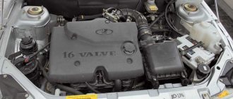
Engine 21124 16 valve
Hello ! Help with the problem, I came to the car yesterday, everything worked, before that I cleaned the injectors. The next day the car started up, but after running for 3-5 seconds it stalled and no more spark, no steering wheel sensor, changed it, then I relieve the pressure in the ramp and try to start it, it starts for 4 seconds and stalls. Where to dig?
Please tell me. I'm getting error 78. VAZ 21124 16v europanel 2007
Hello, my VAZ 10, 8 valves had error 14, I cleared it, do I need to go for diagnostics?
Hello, My VAZ 2110 car will not start. I barely started it with a tugboat, the idle doesn’t work and the throttle doesn’t work, but I need to rev it up, what should I do? Tell me. And error 8 shows how to find this malfunction.
VAZ 2112 16-valve, during self-diagnosis it displays error 818.2... help save what is being done)
Hello, the VAZ 2112 stopped starting, the on-board computer shows error 43210
Who can tell me what error number 8 is?
1 Microprocessor error 2 Fuel gauge sensor circuit error 4 High voltage 8 Low voltage 12 Indicator lamp diagnostic circuit faulty 13 No oxygen sensor/LAMDA probe signal 14 Coolant temperature sensor signal high 15 Coolant temperature sensor signal low 16 On-board voltage too high network 17 Low voltage on-board network 19 Incorrect crankshaft position sensor signal 21 High signal level of the throttle position sensor 22 Low level of the throttle position sensor signal 23 High level of the intake air temperature sensor signal 24 No signal from the vehicle speed sensor 25 Low level of the intake temperature sensor signal air 27 High signal level of the CO potentiometer 28 Low signal level of the CO potentiometer 33 High signal level of the mass air flow sensor For GM NIVA: High signal level of the absolute pressure sensor 34 Low signal level of the mass air flow sensor For GM NIVA: Low signal level of the absolute sensor pressure 35 Idle speed deviation 41 Incorrect phase sensor signal 42 Malfunction of the electronic ignition control circuit 43 Incorrect knock sensor signal 44 Lean mixture 45 Rich mixture 49 Vacuum loss diagnostics 51 EPROM error 52 RAM error 53 No CO potentiometer sensor signal For GM NIVA : increased voltage 54 No signal from the octane corrector sensor 55 Depletion at high engine load For GM NIVA: error in the electronic control unit 61 Degradation of the oxygen sensor/LAMDA probe
Errors persist until they are reset manually! Also mistakes add up! Those. If you have errors 8 and 14, the display will show error 22.
Some decodings for the “January” type controller
When using this device, the readings and their interpretation will look like this:
- 12
– diagnostic circuit of the control lamp; - 14,15
– increased and decreased indication of refrigerant temperature; - 16,17
– similar evidence of voltage in the on-board network; - 19
– false signal from the crankshaft position indicator; - 21,22
– interruptions in the supply of voltage to the throttle valve; - 27.28 – difference in readings of the CO exhaust potentiometer;
- 33.34 – indicator of interruptions in mass air flow;
- 35
– violation of idle speed; - 51, 52, 53 – EPROM controller errors;
- 80
– deviation of interaction with the immobilizer.
If desired and with the right approach, timely diagnostics helps to identify malfunctions of various components at an early stage. Error codes for VAZ 2110 and 2112 (8) 16 valves are identical. They can be identified and decrypted using an on-board computer and a connected external controller.
VAZ error codes:
- P0030 - Oxygen sensor heater before the converter, control circuit open
- P0031 - Oxygen sensor heater before the converter, control circuit short to ground
- P0032 - Heater of the oxygen sensor to the converter, short circuit of the control circuit to the board. net
- P0036 - Oxygen sensor heater after the converter, control circuit open
- P0037 - Oxygen sensor heater after the converter, control circuit short to ground
- P0038 - Heater of the oxygen sensor after the converter, short circuit of the control circuit to the board. net
- P0102 - Mass air flow sensor circuit, low signal level
- P0103 - Mass air flow sensor circuit, high signal level
- P0112 - Air temperature sensor circuit, low signal level
- P0113 - Air temperature sensor circuit, high signal level
- P0116 - Coolant temperature sensor circuit, signal out of acceptable range
- P0117 - Coolant temperature sensor circuit, low signal level
- P0118 - Coolant temperature sensor circuit, high signal level
- P0122 - Throttle Position Sensor Circuit Low Signal
- P0123 - Throttle Position Sensor Circuit High Signal
- P0130 - The oxygen sensor before the converter is faulty
- P0131 - Oxygen sensor circuit to converter, low output level
- P0132 - Oxygen sensor circuit to converter, high output level
- P0133 - Oxygen sensor circuit to the converter, slow response to changes in mixture composition
- P0134 - The oxygen sensor circuit to the converter is inactive
- P0136 - The oxygen sensor after the converter is faulty
- P0137 - Oxygen sensor circuit after the converter, low signal level
- P0138 - Oxygen sensor circuit after the converter, high signal level
- P0140 - The oxygen sensor circuit after the converter is inactive
- P0141 - Oxygen sensor after the converter, heater is faulty
- P0171 - Fuel supply system too lean
- P0172 - Fuel system too rich
- P0201 - Cylinder 1 injector, control circuit open
- P0202 - Cylinder 2 injector, control circuit open
- P0203 - Cylinder 3 injector, control circuit open
- P0204 - Cylinder 4 injector, control circuit open
- P0217 - Engine temperature is higher than permissible
- P0230 - Fuel pump relay circuit malfunction
- P0261 - Cylinder 1 injector, control circuit short to ground
- P0263 - Injector driver fault 1
- P0264 - Cylinder 2 injector, control circuit short to ground
- P0266 - Faulty injector driver 2
- P0267 - Cylinder 3 injector, control circuit short to ground
- P0269 - Injector 3 driver malfunction
- P0270 - Cylinder 4 injector, control circuit short to ground
- P0262 - Cylinder 1 injector, control circuit shorted to on-board network
- P0265 - Cylinder 2 injector, control circuit shorted to on-board network
- P0268 - Cylinder 3 injector, control circuit shorted to on-board network
- P0271 - Cylinder 4 injector, control circuit shorted to on-board network
- P0272 - Faulty injector driver 4
- P0300 - Random/multiple misfires detected
- P0301 - Cylinder 1, misfire detected
- P0302 - Cylinder 2, misfire detected
- P0303 - Cylinder 3, misfire detected
- P0304 - Cylinder 4, misfire detected
- P0326 - Knock sensor circuit, signal output out of acceptable range
- P0327 - Knock sensor circuit low signal
- P0328 - Knock sensor circuit, high signal level
- P0335 - Crankshaft position sensor circuit is faulty
- P0336 - Crankshaft position sensor circuit, signal out of acceptable range
- P0337 - Crankshaft position sensor, short to ground
- P0338 - Crankshaft position sensor, open circuit
- — Malfunction of the camshaft position sensor
- P0342 - Phase sensor circuit, low signal level
- P0343 - Phase sensor circuit, high signal level
- P0346 - Phase sensor circuit, signal output out of acceptable range
- P0351 - Ignition coil of cylinder 1 (1-4), control circuit open
- P0352 - Ignition coil of cylinder 2 (2-3), control circuit open
- P0353 - Ignition coil of cylinder 3, control circuit open
- P0354 - Ignition coil of cylinder 4, control circuit open
- P0363 - Misfire detected, fuel supply to idle cylinders is turned off
- P0422 - Neutralizer efficiency below threshold
- P0441 - Gasoline vapor recovery system, incorrect air flow through the canister purge valve
- P0444 - Canister purge valve, control circuit open
- P0445 - canister purge valve, control circuit short to ground or on-board network
- P0480 - Fan relay, control circuit open
- P0481 - Cooling fan 2 circuit malfunction
- P0500 - Vehicle speed sensor is faulty
- P0506 - Idle system, low engine speed
- P0507 - Idle system, high engine speed
- P0511 - Idle speed control, control circuit faulty
- P0560 - On-board network voltage is below the system operability threshold
- P0562 - On-board voltage, low level
- P0563 - On-board voltage, high level
- P0601 - Engine control system controller, ROM checksum error
- P0615 - Additional starter relay, control circuit open
- P0616 - Additional starter relay, control circuit short to ground
- P0617 - Additional starter relay, control circuit shorted to on-board network
- P0627 - Fuel pump relay, control circuit open
- P0628 - Fuel pump relay, control circuit short to ground
- P0629 - Fuel pump relay, control circuit shorted to on-board network
- P0645 - Air conditioning compressor clutch relay, control circuit open
- P0646 - Air conditioning compressor clutch relay, control circuit short to ground
- P0647 - Air conditioning compressor clutch relay, control circuit shorted to board. net
- P0650 - Malfunction indicator lamp, control circuit faulty
- P0654 - Instrument cluster tachometer, control circuit faulty
- P0685 - Main relay, control circuit open
- P0686 - Main relay, control circuit short to ground
- P0687 - Main relay, control circuit shorted to on-board network
- P0691 - Fan relay, control circuit short to ground
- P0692 - Fan relay, control circuit shorted to on-board network
- P1102 - Oxygen Sensor Heater Resistance Low
- P1115 - Faulty oxygen sensor heating circuit
- P1123 - Rich mixture at idle
- P1124 - Lean mixture at idle
- P1127 - Rich mixture at Partial Load
- P1128 - Lean mixture in Partial Load mode
- P1135 - Oxygen sensor heater circuit 1 open, short circuit
- P1136 - Rich mixture in Light Load mode
- P1137 - Lean mixture in Light Load mode
- P1140 - Measured load differs from calculation
- P1141 - Post-converter oxygen sensor 1 heater malfunction
- P1171 - Low level CO potentiometer
- P1172 - High level CO potentiometer
- P1301 - Cylinder 1, misfire detected, critical for the converter
- P1302 - Cylinder 2, misfire detected, critical for the converter
- P1303 - Cylinder 3, misfire detected, critical for the converter
- P1304 - Cylinder 4, misfire detected, critical for the converter
- P1386 - Knock Channel Test Error
- P1410 - Canister purge valve control circuit short circuit to +12V
- P1425 - Canister purge valve control circuit short circuit to ground
- P1426 - Canister purge valve control circuit open
- P1500 - Fuel pump relay control circuit open
- P1501 - Short circuit to ground of the fuel pump relay control circuit
- P1502 - Short circuit to +12V fuel pump relay control circuit
- P1509 - Idle Air Control Circuit Overload
- P1513 - Idle air control circuit short circuit to ground
- P1514 - Idle air control circuit short circuit to +12V, open
- P1541 - Fuel pump relay control circuit open
- P1570 - Immobilizer, circuit faulty
- P1602 - Engine control system controller, power supply loss
- P1606 - Rough road sensor circuit, signal out of acceptable range
- P1616 - Rough Road Sensor Circuit Low Signal
- P1617 - Rough road sensor circuit, high signal level
- P2301 - Ignition coil of cylinder 1 (1-4), control circuit shorted to board. net
- P2303 - Ignition coil of cylinder 2 (2-3), control circuit shorted to board. net
- P2305 - Ignition coil of cylinder 3, control circuit shorted to board. net
- P2307 - Ignition coil of cylinder 4, control circuit shorted to board. net
Errors in ME17.9.7 and M74 controllers
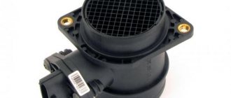
Mass air flow sensor
- P0101 - Diagnosis of reality. Air flow is out of range
- P0102 - Low value diagnostics. The signal period is greater than the upper maximum permissible value
- P0103 - High value diagnostics. The signal period is less than the lower maximum permissible value
Intake air temperature sensor
- P0112 - Low value diagnostic. Voltage is less than the lower maximum permissible value
- P0113 - Diagnostics high value. Voltage is greater than the upper maximum permissible value
Coolant temperature sensor
- P0116 - Diagnosis of reality. Temperature is less than calculated value
- P0117 - Low value diagnostic. Voltage is less than the lower maximum permissible value
- P0118 - Diagnostics high value. Voltage is greater than the upper maximum permissible value
Throttle Position Sensors
- P2135 - Diagnostics of the mismatch between the signals of two sensors. The sensor voltages differ by the threshold value
- P0122 - Low value diagnostic (sensor 1). Voltage is less than the lower maximum permissible value
- P0123 - High value diagnostic (sensor 1). Voltage is greater than the upper maximum permissible value
- P0222 - Low value diagnostic (sensor 2). Voltage is less than the lower maximum permissible value
- P0223 - High value diagnostic (sensor 2). Voltage is greater than the upper maximum permissible value
Accelerator pedal position sensors
- P2138 - Diagnostics of the mismatch between the signals of two sensors. The sensor voltages differ by the threshold value
- P2122 - Low value diagnostic (sensor 1). Voltage is less than the lower maximum permissible value
- P2123 - High value diagnostic (sensor 1). Voltage is greater than the upper maximum permissible value
- P2127 - Low value diagnostic (sensor 2). Voltage is less than the lower maximum permissible value
- P2128 - High value diagnostic (sensor 2). Voltage is greater than the upper maximum permissible value
Injectors
- P0201, P0202, P0203, P0204 - Diagnostics of open control circuit. Driver diagnostics
- P0261, P0264, P0267, P0270 - Diagnosis of control circuit short circuit to ground.
- P0262, P0265, P0268, P0271 - Diagnostics of a short circuit in the control circuit to the on-board network.
Control oxygen sensor
- P0130 - Signal circuit integrity diagnostics. Voltage is less than the lower maximum permissible value or greater than the upper maximum permissible value
- P0131 - Low value diagnostic. Voltage is less than the lower maximum permissible value
- P0132 - Diagnostics high value. Voltage is greater than the upper maximum permissible value
- P0133 - Slow Response Diagnosis. The signal period is greater than the maximum permissible value
- P0134 - Activity Diagnostics. Voltage is less than the upper maximum permissible value and greater than the lower maximum permissible value
- P0030 - Diagnostics of open circuit of the heater. Driver diagnostics
- P0031 - Diagnostics of a short circuit of the heater circuit to ground.
- P0032 - Diagnostics of a short circuit of the heater circuit to the on-board network.
Diagnostic oxygen sensor
- P0136 - Signal circuit integrity diagnostics. Voltage is less than the lower maximum permissible value or greater than the upper maximum permissible value
- P0137 - Low value diagnostic. Voltage is less than the lower maximum permissible value
- P0138 - Diagnostics high value. voltage is greater than the upper maximum permissible value
- P0140 - Activity Diagnostics. Voltage is less than the upper maximum permissible value and greater than the lower maximum permissible value
- P0036 - Heater circuit open circuit diagnostics. Driver diagnostics
- P0037 - Diagnostics of a short circuit of the heater circuit to ground.
- P0038 - Diagnostics of a short circuit of the heater circuit to the on-board network.
Fuel supply system
- P0171 - Diagnosis of poor mixture composition. Fuel correction coefficients are greater than the upper maximum permissible value
- P2187 - Diagnosis of poor mixture composition (at idle).
- P0172 - Diagnostics of the richness of the mixture. Fuel correction coefficients are less than the lower maximum permissible value
- P2188 - Diagnostics of the richness of the mixture (at idle).
- Engine overheating - P0217. Engine temperature monitoring
Misfire for toxicity
- P0300, P0301, P0302, P0303, P0304 - Diagnosis of the presence of misfires affecting toxicity. The number of misfires is greater than the maximum permissible value
Misfire to protect the converter
- P0363, P1301, P1302, P1303, P1304 - Diagnosis of the presence of misfires affecting the converter. The number of misfires is greater than the maximum permissible value
Knock sensor
- P0326 - Low value diagnostics. Normalized signal level is outside the acceptable range
- P0327 - Low value diagnostics. The normalized signal level is less than the lower maximum permissible value
- P0328 - High value diagnostics. The normalized signal level is greater than the upper maximum permissible value
Crankshaft position sensor
- P0335 - Signal presence diagnostics. Change in air flow in the absence of a signal from the crankshaft position sensor above the maximum permissible value
- P0336 - Diagnosis of reality. The controller counts the wrong number of teeth per revolution of the crankshaft
Camshaft position sensor
- P0340 - Diagnostics of signal presence. The sensor signal does not change when the engine is running
- P0342 - Low value diagnostics. Low sensor signal for several crankshaft revolutions
- P0343 - High value diagnostics. High sensor signal for several crankshaft revolutions
Ignition coils
- P0351, P0352 - Diagnostics of open circuit. The primary circuit current is less than the maximum permissible value
- P2301, P2304 - Diagnostics of a short circuit to the on-board network. The primary circuit current is greater than the maximum permissible value
- Neutralizer - P0422. Determining the capacity of stored oxygen by comparing the amplitude range of the control and diagnostic oxygen sensors
Canister purge valve
- P0441 - Functional diagnostics. The response of the idle control system is greater or less than the maximum permissible value
- P0459 - Diagnostics of a short circuit to the on-board network. Driver diagnostics
- P0458 - Diagnostics of a short circuit to ground.
- P0444 - Open circuit diagnostics.
Cooling fan relay 1
- P0692 - Diagnostics of a short circuit to the on-board network. Driver diagnostics
- P0691 - Diagnostics of a short circuit to ground.
- P0480 - Open circuit diagnostics.
Cooling fan relay 2
- P0694 - Diagnostics of a short circuit to the on-board network. Driver diagnostics
- P0693 - Diagnostics of a short circuit to ground.
- P0481 - Open circuit diagnostics.
- Cooling fan - P0485. Diagnostics of cooling fan supply voltage
- Vehicle speed sensor - P0500. Signal presence diagnostics
- Brake pedal sensor - P0504. Diagnostics of sensor signal mismatch time
Onboard voltage
- P0560 - Diagnosis of value validity. voltage in circuits Cl. "30" and Cl. “15” differs by the threshold value
- P0562 - Low value diagnostic. Voltage is less than the lower maximum permissible value
- P0563 - High value diagnostic. Voltage is greater than the upper maximum permissible value
- P1602 - Supply voltage diagnostics. Power failure
Controller
- P1640 - EEPROM diagnostics. EEPROM test error
- P0601 - Software checksum diagnostics. Invalid checksum
- P0606 - Internal controller checks. ADC is faulty
- P2105 - The monitoring module is faulty.
Starter relay
- P0615 - Open circuit diagnostics. Driver diagnostics
- P0616 - Diagnosis of a short circuit to ground.
- P0617 - Diagnostics of a short circuit to the on-board network.
Fuel pump relay
- P0627 - Open circuit diagnostics. Driver diagnostics
- P0628 - Diagnosis of a short circuit to ground.
- P0629 - Diagnostics of a short circuit to the on-board network.
A/C clutch relay
- P0645 - Open circuit diagnostics. Driver diagnostics
- P0646 - Diagnostics of a short circuit to ground.
- P0647 - Diagnostics of a short circuit to the on-board network.
How to remove information about corrected errors from the controller memory
Sometimes, after troubleshooting, error messages remain in memory and periodically appear on the panel.
To clear an error code from memory:
- Write down and check for irrelevant codes that appear.
- Reset the daily mileage readings by pressing the corresponding button, after which the error code is guaranteed to be deleted from memory.
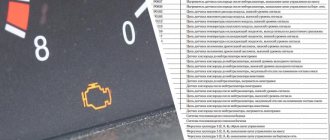
How to get rid of the "Check Engine" message
Sometimes drivers see a glowing orange icon at the bottom of the instrument panel. This is how the computer reports an engine malfunction. Self-diagnosis will not allow you to determine and correct the cause of the motor problem. However, the error often appears on serviceable cars. Therefore, to reset the problem code:
- Turn on the ignition, but do not start the car.
- Open the hood and use a wrench to loosen and remove the negative terminal on the battery.
- After a minute, return the terminal to its original position.
- Close the hood and turn the ignition key to position “0”.
- Turn the ignition back on and start the engine. After a short time the error should disappear.
What does error 8 mean on the VAZ-2114 instrument panel and how to fix it
The VAZ-2114 is based on mechanics, so for many drivers it comes as a real surprise that the car has self-diagnosis.
This allows you to avoid checking the operation of the machine at a service station using expensive equipment; the fault can be determined with your own hands at any convenient time, and then quickly eliminated. Diagnostics of the VAZ-2114 involves displaying an error code on the on-board screen, which indicates a specific breakdown. Error 8, displayed on the panel, stands for insufficient voltage in the machine network. We will tell you how to fix the problem, but first we will teach you how to enable self-diagnosis of the VAZ-2114.
Instructions for self-diagnosis of VAZ-2114
To enable self-diagnosis in a domestic car, take the driver’s seat and sequentially perform the following manipulations:
- Find the odometer key on the instrument panel, press and do not release.
- At this time, turn the key in the ignition, setting format 1.
- The odometer key can now be released.
- Observe what changes occur on the instrument panel, namely the arrows should jump.
- Press the odometer key again and release it again, after which numbers indicating the firmware of the vehicle’s on-board computer are visible on the speedometer.
- All that remains is to press the odometer key a third time, and then remove your hand, and the display of a combination of faults on the screen will not take long. Please note that at a service station the error consists of 4 digits; if you diagnose it yourself, it assumes 2 digits.
Car diagnostics
The appearance of a lit “Check Engine” lamp on the instrument cluster signals the driver that a problem has arisen in the vehicle’s electrical system. You need to understand that checking the vehicle yourself and at a service station can give different results. Special equipment available to professionals will allow more accurate detection of faults.
Self-diagnosis
On a VAZ 2115, the owner can do independent diagnostics and find out what errors are stored in the memory of the engine control unit. The procedure is carried out by calling up fault codes on the dashboard or using a diagnostic adapter.
To carry out diagnostics on the electronic instrument panel, you must perform a certain sequence of actions:
- Sit in the driver's seat of the car, insert the key into the ignition and press the daily mileage reset button located on the instrument cluster.
- Turn the lock key to the ignition switch position.
- Release the key, starting the self-diagnosis process. Visually, this will look like turning on the backlight, all signal lamps, possible symbols on the LCD screens and testing the instruments (the arrows will move across the entire scale in both directions).
- Press the key again and release. The second press displays the software version of the instrument cluster on the screen located under the speedometer (inscription like Uer x. x).
- Press the key again, after which the errors in the memory will be displayed on the screen.
Instrument cluster VAZ 2115, the button is located on the right side of the speedometer
The driver can perform self-diagnosis on the electromechanical panel and the “January-4” control unit according to the following sequence:
- Turn off the ignition.
- Open the diagnostic connector cover located on the center console.
- Connect contact B to the negative terminal of the battery (to the body). Contact A, connected to the engine crankcase, is suitable for this.
- Turn on the ignition. The “Check Engine” lamp will flash code 12, which means the diagnosis has begun. The light signals are given as follows - a long flash, then a pause (about 2 seconds), two short flashes, a long pause (about 3 seconds). Signal 12 is sent three times. If there is no signal, the diagnostic system is inactive or faulty. After this, the Check Engine light will flash and list the errors in memory. Each code is repeated three times. If there are no errors in the memory, code 12 will continue to be transmitted.
What does error 8 mean and how to fix it
Error 8, reflected on the on-board computer of the VAZ-2114, means low voltage on the on-board network. Reasons that can cause a decrease in voltage in the VAZ-2114:
- the battery is almost completely discharged;
- erasing or “freezing”, lack of adequate operation of the brushes on the generator.
That is, you can remove error 8 and correct problems in the operation of the VAZ-2114 by charging the car battery or replacing the brushes on the generator, and all this can be done without turning to specialists, in your own garage with your own hands.
Removal and modification
Here's a quick look at the device and control panel icons. If for some reason she refuses, don’t immediately panic. Most often, the reason is the absence of contacts in some place in the wiring. But of course, if you wish, you can completely change or tune the panel.
For example, remove the cover and replace the light bulbs with brighter LEDs. Such a panel works brighter and the signals sent by the car will be more noticeable to the driver. If desired, you can install a more solid europanel, which will transform the interior.
To remove the panel you need:
Source
How to charge a VAZ-2114 battery yourself
You need to know how to charge a VAZ-2114 battery not only if self-diagnosis shows error 8. Correct and timely charging of the battery will extend its life. To do this, follow the recommendations of experts:
- Remove the battery and carefully go over it with a cloth, your task is to thoroughly clean it from dirt. Focus on the top of the piece.
- Now check the electrolyte load indicators. According to service station workers, the electrolyte level should be between the minimum and maximum icons located on the battery case. If the electrolyte is not enough, it must be added to the norm.
- Charge the battery when the plugs are turned out with a current of 5.5 A. Also monitor the density of the electrolyte.
- While charging, the battery can reach a temperature of 40 degrees, this is the maximum allowable value. However, experts believe that even this figure is too high - it is necessary to lower it to 27 degrees by interrupting battery charging.
- When should charging be completed? If a large volume of gas comes from the battery, the electrolyte voltage and its density are kept constant. 3 measurements are taken as a basis.
- If the density is different, then it needs to be adjusted. The increased density can be reduced by adding distilled liquid to part of the material. If it is low, use the method of adding electrolyte with increased density.
- When the adjustment has been made, do not remove the battery from charging for up to half an hour, then turn it off and check the electrolyte readings after half an hour. If the material level is too high, use a rubber blower to remove excess material.
How to fix error 10?
Car service specialists check error 10 with an OBD-2 scanner. Since low voltage in the network is a consequence of weak battery charging, first check its charge level. Every self-respecting car owner is recommended to have a multimeter to monitor the condition of electrical wiring, leads, contact connections and the battery itself. Sometimes VAZ 2114 on-board computers provide erroneous information. This happens because the sensors going from the battery to the computer have “intermediaries” in which the voltage is lost. Therefore, to ensure that the readings are correct, the battery should be measured directly, preferably with a digital multimeter. It is more convenient to use and has less distortion than the traditional one. The voltage in the battery is measured first with the engine running. Normally, the readings should be 13.5-14 V. If it reads 14.2 V or higher, then the battery is discharged and the generator is overloaded to maintain the required voltage. If the multimeter shows a voltage of 13-13.4 V when the engine is running, it means that the battery is not fully charged, and therefore the generator is not working well. The alternator brush may be worn out and require replacement. Pictured: worn generator brushes. New brushes must protrude no less than 5 mm.
If the battery voltage shows less than 11 V when the engine is not running, then the battery is discharged, and before diagnosing the fuel sensor, it must be charged and make sure that the generator is working normally.
It should be taken into account that in cold weather the measuring device may show increased voltage in the vehicle's electrical network for the reason that the battery may have discharged a little overnight due to sub-zero temperatures, or the electronics have reacted to the lower air temperature and are putting more charge into the battery . There is nothing wrong with increased battery voltage. As soon as the electrical consumers turn on, the voltage will equalize.
In addition to the charging state, it is also necessary to inspect the terminals for the presence of oxidation. If necessary, they are cleaned. After making sure the condition of the battery, charging it if necessary, after checking the generator and its brushes, you should again reset all indicators by de-energizing the computer. If the error does not disappear or it changes to number 2, or 0460, you should proceed to checking the fuel level sensor circuit. For this you will also need a multimeter. During the check, it is necessary to inspect the contacts on the FLS itself, ring the wiring coming from it for a short circuit or break. It is also necessary to inspect the sensor itself. It is located next to the submersible fuel pump under the gas tank cap.
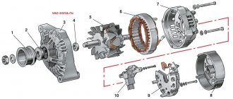
How to replace generator brushes
To get rid of error 8, which occurred in the VAZ-2114 due to worn alternator brushes, follow these instructions:
- Remove the wiring harness.
- Disconnect the rubber cap from the terminals of the plus wires, which is designed to protect the part. To do this, unscrew the wire fixing nut and remove the wires from the generator housing.
- Remove the black casing, made of plastic, by disconnecting 3 fasteners on spring mechanisms located along the perimeter of the block.
- Find the regulator responsible for adjusting the voltage and use a Phillips head screwdriver to unscrew it.
- All that remains is to pull out the regulator along with the brushes attached to it, and then disconnect the wire block.
- Now replacing the brushes will not be difficult.
- Installation of the updated VAZ-2114 voltage generator is carried out according to the same instructions, but in reverse order.