The sensors are connected directly to the block, which is a computing module. The VAZ electrical circuit includes a sealed tank. On carburetor and injection engines, it is imperative to pay attention to the wires that transmit high voltage to the spark plugs.
On a VAZ injector with 8 valves, the electrical circuit has exactly these features. VAZ 21099 Complete replacement of electrical wiring. How to celebrate Bodyworker's Day.
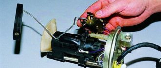
Relay for monitoring the health of brake light lamps and side lights. Only after some time more modern injection versions appeared. They are necessary to power the sensor system, electric fuel pump, on-board computer and other components. On-board control system display unit. Only the modification of the starter may differ.
Subsequently, the controller, based on the information coming from the on-board computer, makes a decision on the position and duration of opening of the injector damper. Instrument cluster. How to connect motor wiring from brains
Diagnostics using ODB-2 scanner
The general technical condition of the car can always be checked using a personal diagnostic car scanner. Of the options available on the market, we recommend paying attention to the Korean-made scanner Scan Tool Pro Black Edition. This model is perfectly compatible with most domestic and foreign cars.
A special feature of the device is comprehensive car diagnostics. Unlike analogues, this auto scanner is capable of diagnosing not only the engine, but also ABS, gearbox, transmission, airbag, air conditioning system, etc. The device is also great when used as an on-board computer: in real time it displays speed, revolutions, readings from all available sensors, oil pressure, temperature and much more.
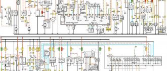
Diagram of injection VAZ 2110 16 valves
| 1 – block headlight | 2 – front brake pad wear sensor | 3 – fan motor activation sensor |
| 4 – electric motor of the engine cooling system fan | 5 – sound signal | 6 – generator |
| 7 – oil level sensor | 8 – carburetor solenoid valve control unit | 9 – heater controller |
| 10 – recirculation valve switch | 11 – backlight lamp for heater control levers | 12 – switch |
| 13 – carburetor limit switch | 14 – oil pressure warning lamp sensor | 15 – spark plugs |
| 16 – carburetor solenoid valve | 17 – coolant temperature indicator sensor | 18 – ignition distributor |
| 19 – ignition coil | 20 – starter | 21 – heater fan electric motor |
| 22 – additional resistor of the heater electric motor | 23 – speed sensor | 24 – reverse light switch |
| 25 – micromotor gearbox for heater damper drive | 26 – recirculation valve | 27 – brake fluid level sensor |
| 28 – blocks for connecting the rear window washer motor | 29 – battery | 30 – windshield washer motor |
| 31 – washer fluid level sensor | 32 – coolant level sensor | 33 – windshield wiper motor |
| 34 – mounting block | 35 – blocks for connecting the warning light harness | 36 – external lighting switch |
| 37 – instrument cluster | 38 – rear fog light switch | 39 – fog light indicator lamp |
| 40 – indicator lamp for heated rear window | 41 – hours | 42 – rear window heating switch |
| 43 – steering column switch | 44 – block for switching wires when installing headlights of another type | 45 – instrument lighting switch |
| 46 – ignition switch | 47 – blocks for connecting the wiring harness for headlight cleaners | 48 – socket for a portable lamp |
| 49 – directional lamp | 50 – brake light switch | 51 – interior lamp |
| 52 – on-board control system unit | 53 – fuel level indicator sensor | 54 – hazard warning switch |
| 55 – driver’s seat belt sensor | 56 – cigarette lighter | 57 – ashtray illumination lamp |
| 58 – glove compartment lamp switch | 59 – block for connecting the on-board computer | 60 – glove box lighting lamp |
| 61 – side turn signal | 62 – switch in the front door pillar | 63 – switch in the rear door pillar |
| 64 – parking brake warning lamp switch | 65 – trunk light | 66 – cabin air temperature sensor |
| 67 – external rear light | 68 – internal rear light | 69 – license plate light |
| 70 – block for connecting the rear window heating element | 71 – block for connecting an additional brake signal |
Legend
For ease of maintenance and installation, the electrical wires in the diagrams are made in different colors, identically laid in the car, so that their purpose can be visually determined.
For brevity, colors are indicated by the first letters of the name:
- Blue – “G”;
- Brown – “K”;
- Gray – “C”;
- White – “B”;
- Orange – “O”;
- Yellow – “F”;
- Black – “H”;
- Green – “Z”;
- Pink - "R".
Thanks to the colors, it is easy to determine whether the rein belongs to a particular chain
For reference: the red wire is traditionally used to supply power from the positive terminal of the generator or battery. Therefore, in all diagrams contained in the factory instructions, it is designated by the letter “P”.
The article Wiring diagram for VAZ 21074 injector: understanding the intricacies will also be useful.
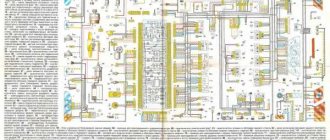
Diagram of injection VAZ 2110 8 valves
| 1 – block headlight | 2 – front brake pad wear sensors | 3 – sound signal |
| 4 – cooling system fan | 5 – reverse light switch | 6 – battery |
| 7 – generator | 8 – oil pressure warning lamp sensor | 9 – oil level sensor |
| 10 – spark plugs | 11 – nozzles | 12 – idle speed regulator |
| 13 – electronic control unit blocks | 14 – throttle position sensor | 15 – crankshaft position sensor |
| 16 – ignition module | 17 – coolant temperature indicator sensor (for instrument cluster) | 18 – starter |
| 19 – diagnostic block | 20 – coolant temperature sensor (for engine management system) | 21 – speed sensor |
| 22 – fuel pump activation relay | 23, 35, 39 – fuses | 24 – electric fuel pump |
| 25 – micromotor gearbox for heater damper drive | 26 – recirculation valve | 27 – heater fan |
| 28 – windshield washer pump | 29 – washer fluid level sensor | 30 – brake fluid level sensor |
| 31 – coolant level sensor | 32 – windshield wiper gear motor | 33 – additional heater fan resistor |
| 34 – injection system power supply relay | 36 – adsorber purge valve | 37 – mass air flow sensor |
| 38 – relay for turning on the cooling fan | 40 – external lighting switch | 41 – knock sensor VAZ-2110 injector |
| 42 – oxygen concentration sensor (heated lambda probe) 42* – CO potentiometer (installed on cars running on leaded gasoline; in this case, an oxygen concentration sensor is not installed) | 43 – fog light indicator lamp | 44 – indicator lamp for heated rear window |
| 45 – fog light switch | 46 – rear window heating switch | 47 – instrument cluster |
| 48 – mounting block | 49 – fuel level sensor | 50 – ignition switch |
| 51 – instrument backlight brightness control | 52 – steering column switch | 53 – backlight lamp for heater control levers |
| 54 – hazard warning switch | 55 – electronic heater control unit; | 56 – recirculation valve switch |
| 57 – display unit of the on-board control system | 58 – side direction indicators | 59 – temperature sensor for the heating system |
| 60 – interior lamp | 61 – front interior lamp | 62 – socket for a portable lamp |
| 63 – electronic watch | 64 – switches in the front door pillars | 65 – switches in the rear door pillars |
| 66 – glove box lighting lamp | 67 – glove box lighting switch | 68 – cigarette lighter |
| 69 – ashtray lighting lamp | 70 – brake light switch | 71 – rear window heating element |
| 72 – external rear lights | 73 – internal rear lights | 74 – license plate lamps |
| 75 – trunk lighting lamp | ||
Heated seats and rear window
These two systems are very similar to each other, as they consist of the same components:
- Fuse to protect the circuit.
- Electromagnetic relay for switching a power circuit.
- Illuminated power button.
- Wire harnesses.
- Heating elements.
It is imperative to use electromagnetic relays. They are available in the electrical circuit for heated seats of the VAZ-2110. With their help, you can get rid of switching with a high current button.
As a result, the button on the dashboard switches only the low-current control circuits of the electromagnetic relay windings. The rear window heater has a similar design. If the car has heated rear view mirrors, then a similar scheme is used.
Detailed diagrams of important components of the VAZ 2110 car
If you need an exact diagram of any component of your car, then I recommend that you familiarize yourself with these diagrams.
Generator system connection diagram
| 1 – battery | 2 – generator | 3 – mounting block |
| 4 – ignition switch | 5 – battery charge indicator lamp, located in the instrument cluster |
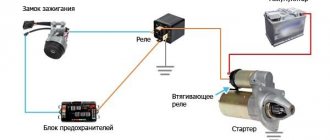
VAZ 2110 starter connection
| 1 – battery | 2 – generator | 3 – starter |
| 4 – ignition switch |
Diagram of the ignition system on the VAZ 2110
| 1 – battery | 2 – ignition switch | 3 – ignition relay |
| 4 – spark plugs | 5 – ignition module | 6 – controller |
| 7 – crankshaft position sensor | 8 – master disk | A – matching devices |
Contactless ignition system diagram
| 1 – ignition coil | 2 – ignition distributor sensor | 3 – spark plugs |
| 4 – switch | 5 – ignition switch |
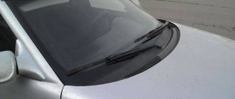
Turning on the rear window wiper and washer
| 1 – washer motor | 2 – mounting block | 3 – ignition switch |
| 4 – rear window wiper and washer switch | 5 – rear window wiper gear motor | K6 – additional relay |
| A – to power supplies | B – the order of conditional numbering of plugs in the gear motor block |
Diagram of the automatic heater control system
| 1 – fan motor | 2 – additional resistor | 3 – controller |
| 4 – mounting block | 5 – ignition switch | 6 – cabin air temperature sensor |
| 7 – recirculation switch | 8 – recirculation valve | 9 – micromotor gearbox for heater damper drive |
| A – to the instrument lighting switch | B – to power supplies |
Common faults and solutions
What problems can occur in the operation of the electrical circuit:
- Short circuit. In practice, such problems are caused by damaged wires or breakdown of insulation.
- Broken wiring. Problems of this kind are solved by replacing damaged circuits. If the damage is minor, then the defective area can be wrapped with several layers of electrical tape.
- Poor contact of the equipment with the vehicle's electrical network. In case of such problems, you should immediately check the quality of the connection, that is, make sure that the contact on the connector is inoperative. There is a possibility that the malfunction can be “defeated” by disconnecting and connecting the connector.
- Power surges in the network. Malfunctions of this type may be associated with the use of more powerful energy consumers than the on-board network allows. The most common mistake is using a splitter in the cigarette lighter. The cigarette lighter socket is designed for a certain power. Therefore, when the driver tries to connect several energy consumers to this connector, this can provoke both a blown fuse and a voltage surge.
- Failure of the safety device. The safety element itself is used to protect the equipment, but from time to time these parts burn out due to wear and tear. If burnout occurs systematically, then you need to look for a problem in the wiring.
- Malfunctions in the ignition system, in particular, we are talking about high-voltage wires. This problem doesn't happen often, but if it does happen, it can take a long time to find it. The fact is that the symptoms of damage to high-voltage wires are similar to the signs of failure of spark plugs. The power unit begins to oscillate while driving, its power deteriorates, and starting may be difficult. Therefore, when such symptoms appear, high-voltage cables should be diagnosed. The insulation in them may be damaged (video author Evgeniy Churilov).
What if the electrical equipment in the car stops working? First you need to check the presence of voltage in the electrical circuit.
For diagnostics you will need a voltmeter; the checking procedure is performed as follows:
- First, the tester should be set to voltmeter mode.
- One of the tester's terminals must be connected to the negative terminal of the battery or the body of your "ten". Make sure that the contact on the body is good.
- The other probe of the tester is connected to the supply wire in the electrical circuit being diagnosed. Of course, before doing this, you should disconnect the equipment outputs.
- If numbers eventually appear on the tester screen, this indicates that there is voltage in this section of the circuit and the wiring in it is working. Similar actions are performed with other electrical circuits.
How to find a short circuit:
- First, the fuse itself, which is responsible for the circuit being diagnosed, is removed from the fuse block socket.
- The tester should be switched to voltmeter mode; one of its probes is installed in the fuse socket. Please note that all electrical equipment in this circuit should be turned off.
- Try to move the wire a little, if at this moment values begin to appear on the tester display, this indicates that you have found a circuit with a short circuit.