Features of the Niva cooling system.
The VAZ-21214 engine cooling system is designed for off-road driving, that is, to operate for a long time at low speed and high revs.
This causes the engine to become very hot. Therefore, the Nivas are equipped with a cooling radiator slightly larger than on the classics and two cooling fans. In fact, the machines are operated mainly in urban environments, where the engine operates without overload and the operation of two fans to cool the radiator is practically not needed. In addition, when operating, the Niva cooling fan makes quite a bit of noise, which affects comfort.
How does the Niva fan connection diagram described above work?
When the engine temperature reaches the low temperature sensor response threshold, the relay to which it is connected will operate. In this case, the current from the fuse through the relay contacts will flow to the positive brush of the first fan. Then passing through the armature winding to the negative brush and through the contacts of the additional relay to the second fan motor. At the electric motor collectors there will be ½ of the on-board network voltage. This will lead to a reduction in speed by half, and accordingly the noise will decrease.
If the engine temperature reaches the response threshold of the second sensor or the temperature at which the ECU fans turn on, the additional relay coils and the second fan relay will receive power. The movable contact of the additional relay will switch the wire from the fan motor to vehicle ground, at the same time the second fan relay will close. This will cause the fans to be switched in parallel.
“If you notice an error in the text, please highlight this place with the mouse and press CTRL+ENTER”
The VAZ-21214 engine cooling system is designed for off-road driving, that is, to operate for a long time at low speed and high revs. This causes the engine to become very hot. Therefore, the Nivas are equipped with a cooling radiator slightly larger than on the classics and two cooling fans.
Description of the Niva fan circuit.
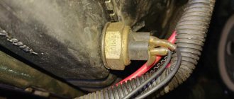
In the factory circuit, the fans are connected in parallel to each other, and switching on is carried out automatically through two relays. Automatic activation depends on the engine type. On a carburetor engine, activation is carried out by a sensor mounted on the radiator. The temperature in this case depends on the response temperature of the sensor indicated on the housing. On an injection engine, the fans are turned on by the engine control unit when the temperature recorded in the control program is reached.
Methods for connecting fans.
There are two ways to reduce fan motor speed. The first is to connect an additional resistance of sufficient power in series with each fan motor. The second way is to connect Niva fans in series. The disadvantage in the first case is the search for resistance, which will also heat up. In the second case, a minimum of alterations are required. It is enough to pull out the negative wire from the connector of the first fan, and the positive wire from the second connector. After this, connect the free terminals on the motors with a wire of the appropriate cross-section. But in this case, in order to turn on the fans at high speeds, you will need to redo everything back.
If you want the fans to be able to operate at low and high speeds depending on the heating of the engine, then you will need to install an additional relay that will switch the fans from serial to parallel connection. This relay can be controlled manually or automatically. You can also combine both control methods. The design of the Niva fan connection diagram can be different, depending on the type of engine and your preferences.
When switching manually, you need to install a switch; a key is best suited, and for automatic control, an additional switching sensor with a response temperature lower than the main one.
Fan malfunctions
Let's look at what malfunctions of the Niva cooling fan may occur and how to identify them. The most common malfunction is blown fuses.
The fuse blows.
A single occurrence of such a malfunction does not indicate a faulty wiring or the fans themselves. During operation, fuses heat up and eventually fail. They are easy enough to replace. They are located on a carburetor car in the lower fuse block, and on an injection car in an additional block near the driver's door pillar.
If the fuses blow immediately when the fans are turned on, then it is necessary to find a short circuit or replace the fan. To determine the location of the malfunction, it is enough to disconnect the connector on the fan motor and connect the wires on the radiator sensor with each other with the ignition on.
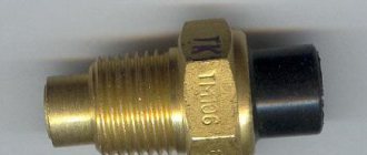
On an injection engine, to check it is necessary to remove the chip from the temperature sensor, which is located on the thermostat. In this case, the engine control unit will go into emergency mode and activate a program for working with a faulty temperature sensor and turn on the fan relay. If the fuse burns out, then it is necessary to find and eliminate the short circuit. If the fuse remains intact, then the problem is most likely in the fan motor. Faulty fans are stuck or difficult to rotate. This may be caused by the stator magnet falling off or the armature bushings wearing out. A faulty fan should be replaced.
The fan does not turn on
Another common malfunction is when the fan does not turn on when the operating temperature is reached. The reason may be a malfunction of the fan sensor on a carburetor car or the engine control unit on an injection car, a relay malfunction, broken wires, or a malfunction of the fan motor.
It is better to start troubleshooting by checking the temperature sensor or control unit. This is done as described earlier by bridging the wires on the carburetor engine sensor or removing the chip from the temperature sensor on the injection engine. If the fans do not work, then you need to check the power relay.
The relays are located under the instrument panel on the front wall. To check, remove the chip from the relay and check for the presence of power at pins 30 and 85. If there is no power, check the condition of the fuse and wires. If there is power, connect terminals 86 and 85 of the relay with a test lamp. If the warning lamp does not light up, then the wire from the ECU connector to the relay socket is broken or the ECU itself is faulty. A lit lamp indicates a relay malfunction.
To test the relay, connect pins 87 and 30 with a piece of copper wire, which should trigger the fans. If this does not happen, then connect a test lamp to the connector without removing the jumper from the relay connector. If the lamp does not light up, then connect one end of the test lamp to the housing, and with the other, check for the presence of a plus on the connector. If the control lamp does not light up, then there is a break in the wire from the relay to the fan connector. Accordingly, the glow of the lamp indicates poor contact of the negative wire with the body or a wire break. The presence of power and minus indicates a malfunction of the electric motor.
If the fan starts working when the relay terminals are bridged, it is necessary to check the condition of the wires connecting the temperature sensor or the engine control unit, depending on the type of engine.
Source
Serial connection of fans.
Let's look at the diagram Connecting Niva fans in a serial connection. To connect the fans in series we need an additional relay. A universal five-pin relay of type 98.3777 is suitable, which is best placed next to the fans. Terminals 85 and 86 of this relay are the terminals of the electromagnet coil. Pin 30 is a moving contact, and pins 87 and 87A are fixed contacts. From the chip connected to one of the fans, we remove the negative wire; it is usually black. We connect this wire to pin 87A of the relay, and connect the free space with a wire to pin 30. Pin 87 is connected to the positive wire of the second fan. Now, when the relay is closed, the fans will be connected in series, and when disabled, in parallel. From the socket of the standard fan switching relay, above which the switching was carried out, we remove the wire from the electromagnet coil coming from the engine control unit or switching sensor and connect it to pin 85 of the added relay. Pin 86 is connected to the ground of the car. The freed output of the standard relay must be connected to an additional power sensor or key.
On carburetor cars, you can use two switching sensors with different response temperatures. For example, for low speeds with a switching temperature of 78 - 82, and for full speeds 90 - 95. You can install an additional sensor in the upper pipe. For injection engines it is somewhat simpler; if there is space on the radiator, then place the sensor there. If there is no space, you can make an insert into the upper pipe and place it there.
System structure and principle of turning on fans
Everything works as follows.
- The radiator and engine block are looped into a single system using pipes. Between them there is a rheostat - a damper with a temperature-sensitive element inside.
- When a certain temperature is reached, the damper opens and the liquid begins to circulate in a large circle.
- If passive cooling fails, the engine temperature rises. The head cooling fans come into play. When the temperature limit is overcome, the DTOZh sends an impulse to the BC.
- The processed signal closes the relay and the fan turns on. To improve system performance, the devices are paired. Dubbing helps prevent overheating if one of the devices breaks down. At the same time, the connection diagram for active coolers implies their simultaneous and separate activation.
Heating and ventilation system. VAZ 21213, 21214 (Niva)
The cooling system is liquid, closed type, with forced circulation. The tightness of the system is ensured by valves in the expansion tank plug. The inlet valve is normally open (the gap between it and the rubber gasket is 0.5–1.1 mm) - in this case, the system communicates with the expansion tank. When the engine heats up, the liquid expands and is forced into the tank; when it cools, it returns back. The inlet valve closes when there is a sharp increase in pressure in the system (boiling liquid), while the outlet valve is also closed. It opens when the pressure in the system reaches approximately 0.5 kgf/cm2, which increases the boiling point of the liquid and reduces its losses. The thermal operating conditions of the engine are maintained by a thermostat and a radiator fan. On a carburetor engine, the fan is mechanically driven and mounted on the coolant pump pulley. On an engine equipped with an injection system, two electric fans are installed in front of the radiator and are activated by command from the electronic engine control unit.
Injection engine cooling system
The coolant pump is a vane, centrifugal type, driven from the crankshaft pulley by a V-belt. The pump housing is aluminum. The roller rotates in a double-row bearing with a lifetime supply of lubricant. The outer ring of the bearing is locked with a screw. A pulley hub is pressed onto the front end of the roller, and a plastic impeller is pressed onto the rear end. For the correct position of the pump pulley groove, the distance from the mating surface of the pump cover to the outer end of the hub must be 84.4 ± 0.1 mm. When installing the cover with the gasket, check the gap of 0.9–1.3 mm between the impeller blades and the pump housing. To do this, you can use plasticine rollers: they are placed on equidistant impeller blades, a cover is installed, the nuts securing it are tightened, then the cover is removed and the remaining thickness of the plasticine is measured - it is equal to the gap.
Axial and radial play in the pump bearing that can be felt by hand is not allowed. If the bearing or self-pressing seal of the pump fails, it is recommended to replace the pump cover complete with the roller and impeller.
The redistribution of liquid flows is controlled by a thermostat with a solid heat-sensitive element. On a cold engine, the thermostat valve closes the pipe leading to the radiator, and the liquid circulates only in a small circle (through the thermostat bypass pipe), bypassing the radiator. The small circle includes the heater radiator, intake manifold, carburetor heating unit (on engine 21213) or throttle assembly (on engine 21214). At a temperature of 78–85°C, the valve begins to move, opening the main pipe; in this case, part of the liquid circulates in a large circle through the radiator. At a temperature of about 90°C, the main valve opens completely, and the bypass valve closes, and all the liquid circulates through the engine radiator. The main valve stroke must be at least 6.0 mm.
You can evaluate the serviceability of the thermostat by heating the lower radiator pipe: it should be cold until the liquid temperature (according to the indicator) reaches 80–85°C, and hot when it rises to 85–90°C. The thermostat is beyond repair. In case of malfunction, loss of tightness, or deformation of the pipes, it is replaced.
The radiator consists of two vertical plastic tanks (the left one has a baffle) and two horizontal rows of round aluminum tubes with pressed-on cooling plates. To increase cooling efficiency, the plates are stamped with a notch. The tubes are connected to the tanks through a rubber gasket. The liquid is supplied through the upper pipe and discharged through the lower. There is a coolant drain plug at the bottom of the left reservoir.
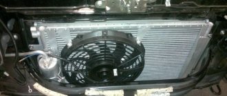
For better radiator airflow, casings are designed to direct air flow from the fan(s).
On the 21213 engine, the main fan shroud consists of two halves (lower and upper), the lower half has a rubber seal on the radiator side. An additional guide casing is installed in front of the radiator. On the 21214 engine, electric fans rotate in a casing in front of the radiator.
The expansion tank is made of translucent polyethylene, which allows you to visually monitor the fluid level (3–5 cm above the “MIN” mark on a cold engine).
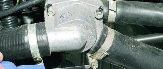
To monitor the coolant temperature, a sensor is screwed into the engine cylinder head and is connected to a temperature gauge on the dashboard. An additional temperature sensor is installed in the exhaust pipe of the 21214 engine, which provides information to the electronic engine control unit (see here).
Purpose and design
This is a module designed to be included in the on-board circuit of a motor that consumes high current. The fan motor is powered by electricity with a current of 20-35A, which is unacceptable for inclusion in a low-voltage control system - the wiring will melt. The Niva has only three relays, two for the left and right fans separately and one common. Each device has its own number in the on-board network. The principle of operation and purpose of the relay is relevant for cars of all types 2004, 2010, 2022 and other years of production.
Inside, the relays have an identical design. There is a low part, a transformer and a high part. Also two pairs of contacts, one normally closed, the second open. When a pulse is applied to the lower part, a magnetic field is formed on the windings, and the contact group on the high side closes - power is supplied to the fan motor.
The cooling screw operates in two modes. When the engine heats up to 99 degrees Celsius, the first fan is turned on, after passing the 101⁰C mark, the second one is connected. If the system cannot cope, the motors switch to higher speeds.
Fan relay diagram
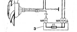
The figure shows the power supply circuit for the electric fans of the cooling system of the installation. Design elements are presented by numbers.
- 1/7 – left and right fan motors;
- 2 – additional power relay;
- 3 – fuse;
- 4 – power controller;
- 5 – auxiliary resistor;
- 6/8 – main relay for turning on the right and left electric motor, respectively;
- A/C – negative/positive battery terminal;
- B – to the main ignition relay.
Niva Chevrolet: engine cooling fan relay
Everyone knows that modern cars have a water engine cooling system in their design, which allows many times to increase the service life of not only the engine, but also the entire mechanism as a whole. The Chevrolet Niva also has a radiator in its design that is filled with coolant. This liquid circulates through the system, thereby cooling the car engine. But the engine temperature exceeds 100 degrees, so if this liquid is not cooled, it will soon turn from cooling to heating. This is precisely why there is a radiator cooling system, the operation of which is carried out by a fan. But since the Chevrolet Niva is equipped with a powerful 1.7-liter engine, two fans are used to cool the radiator. In this article, we will look at how these devices work, or rather, what is the main element of turning on these devices on a Chevrolet Niva SUV.
Fan switching principle
The cooling fan is powered by a constant voltage of 12 V from the battery. They turn on when two sensors located in the engine reach a certain temperature. So, when the first sensor reaches a temperature of 99 degrees Celsius, it is triggered, which causes the first fan to turn on. It has two rotation speed positions - high and low rotation speeds. When the second sensor reaches a value of 101 degrees, then, accordingly, the second device turns on. Thus, the cooling devices of the Chevrolet Niva engine are briefly activated. But we are interested in what role such a small device as a relay, of which there are three on the Chevrolet Niva, plays in this process.
A universal scanner for self-diagnosis of any car.
Relay purpose and design
The relay is designed for switching large load currents. This is a rather complex formulation, so in simple terms, a relay is necessary in order to be able to control electrical circuits where there are large currents. The electric motor of the cooler consumes direct current, the value of which is 20-30 amperes, which means that if it is included in the control circuit (where small currents pass), then all the electronics will fail (the wiring will melt). That is why such an important control element is installed in the design of cars.
Externally, the product is a plastic base, inside of which the mechanism itself is located. There are five (four) contacts on the back side of the base. They are the basis for including a relay in the control circuit.
Inside, the relay mechanism is presented in the form of a coil with a core - it is also the basis for closing the circuit contacts. In the photo below you can see the appearance of the Chevrolet Niva product.
Transfer case location and functions
The transfer case is attached directly to the underbody of the vehicle. But the device vibrates strongly during movement. Therefore, good fixation is necessary.
The transfer case performs the following functions:
- Distribution of torque between the drive axles so that the vehicle's maneuverability is high without causing power circulation.
- Increased wheel torque at high resistance. For example, on uneven or steep roads.
- Ensuring stable vehicle movement at low speeds.
Job
The Shniva cooling system has two active cooling elements. There is a fan for the heater radiator and the main heat exchanger. The following information is relevant for cars of 2010 and other model years.
Fuses are responsible for the correct, stable operation of devices. Fuse links will protect the device from power surges and short circuits.
Pulley fan fuse: where is it located?
Located in close proximity to the corresponding relays. The stove insert is located in the main mounting block under number F18. A 25 amp fuse protects multiple circuits at once.
Possible malfunctions and their causes
If the fans do not turn on on time, the problem may be hiding in the following places.
- Relays or fuses have blown.
- DTOZH does not work correctly.
- The wiring of the device is damaged.
- Incorrect ECU settings.
- The fan motor is damaged or shorted.
Checking the functionality of the sensor, relays and fuses
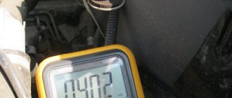
The DTOZH is responsible for the operation of the fans; it is easy to check.
- Prepare a thermometer, multimeter, kettle or bowl of cool water.
- Immerse the sensor in a container and put it on fire, at the same time immerse the thermometer in water.
- When passing thresholds of 5 degrees, you should connect the multimeter to the sensor in resistance mode. At the same time, record the data.
- After heating the water to a boil, take the last measurements and compare the results with the reference table below. If the device indicators differ by more than 10% from the standard, the sensor is changed.
Forced activation of cooling fans
To make this possible, car enthusiasts install an additional switch into the device circuit and power it directly from the battery. The operation of the electronics is disrupted and the on-board computer may generate an error.
To fake the device, users on the network recommend using a scheme.
A relay and a forced switch are added here.
Replacing the Fan Relay
Due to the simplicity of the design, the procedure is performed according to a standard scenario. Access to the mounting block is opened, the terminal of the relay contact group is disconnected. Next, the device is unscrewed from the panel and replaced with a new one.
Reasons why the cooling fan does not work on a Chevrolet Niva
To maintain the optimal temperature in the engine, a cooling system is installed in the car. One of the main elements in this system are fans, thanks to which the required amount of air is supplied to the engine through the radiator core. If it stops working, the Niva Chevrolet cooling fan overheats as excess heat begins to accumulate. Unlike classic cars, it has two fans, making the functioning of the systems much more complicated. If the arrow that shows the temperature is in the red area, and the cooling system refuses to work, and at the same time the cooling fan does not turn on, then the car should be taken to a car service center as quickly as possible, or you should try to find the cause of the malfunction yourself.
- 1 Causes of malfunction
- 2 Checking and removing fans
Causes of malfunction
The first thing you should pay attention to when the system is not working is the state of the fuses, which are located under the front panel, on the passenger side, in a special mounting block. A pair of fuses are responsible for the cooling operation; if the right one fails, then both fans stop working, and if the left fuse blows, then one element can continue to operate.
In addition, the mounting block has three relays that are responsible for operating the fans at different speeds. And if the relay responsible for operation at low speeds burns out, then the cooling system works correctly only at high speeds, and at low speeds the engine begins to heat up. Power is supplied to the relay through a special fuse, which can also fail, causing system failure.
Failure of temperature sensors also affects proper cooling operation. They are located on the engine. They operate when the desired temperature is reached, one when it reaches 90 degrees, and the second when it reaches 101 degrees. It is recommended to start checking with them, this is done this way: the connector is disconnected from the electric motor, and power is supplied to them directly through the battery; if the electric motor is running, then the reason is in the sensors.
Source
Additional transfer case support
In the classic version, the transfer case is attached to the floor of the car body using a pair of rubber-metal brackets. To adjust it in relation to the shaft flange, oval-shaped holes in the brackets are used. Regulating gaskets are sometimes placed between them and the body.
Many people know the Niva as a car with a high level of vibrations, which annoy a number of drivers. Therefore, many car owners install a third support, which allows them to reduce vibrations of the transfer case in longitudinal planes, which can relieve the load on the shaft with an elastic coupling. This design, welded by hand or bought for a small amount in a store (you’ll have to look), when moving on any roads at any speeds, should reduce vibration from the Niva transfer case levers to zero.
Installing a “device” purchased in a store is quite simple. It is necessary to replace three studs on the rear cover of the transfer case with longer ones from the kit. After this, you can screw the transfer case, center it and drill holes in the floor, onto which you can attach the box using washers, nuts, and bolts. That's it, the third support is ready. The mount is located somewhere behind the handbrake.