The design uses a two-contact sensor, which, depending on the temperature, powers the electric motor directly or through resistors; a combination of parallel and series connection. The fan disperses the heat by passing the necessary air flow through the radiator, thereby dissipating the heat into the atmosphere. The fan continues to run briefly even after the ignition is turned off. If the car's design does not provide a fan relay, you will have to install it yourself to force cool the radiator. Therefore, armed with diagrams of the mounting blocks of the native one that should be on the car. How to connect a cooling fan through a button in the cabin. In 3-wire fans, a tachometer output is added. But it also has its disadvantages. To solve this problem, it is necessary to periodically turn on the fan for such a period of time that will allow you to obtain several reliable cycles of the tacho signal. To obtain low speeds, the voltage is reduced, to obtain high speeds it is increased. Refining the fan motor switching circuit Many responsible car enthusiasts can spend hours in the garage, trying not only to eliminate existing problems, but also to prevent the occurrence of new malfunctions through various improvements and modifications. First, let's replace the terminals with a 2-pin chip connected to the cooling fan. How does the cooling fan turn on?
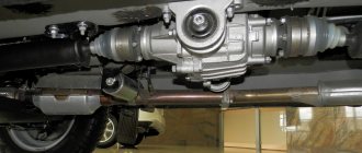
VAZ cooling fan connection diagram
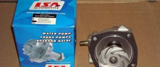
All the main electrical circuits and modifications for connecting the liquid cooling fan (CO) in VAZ cars of various models are provided. What is the essence of VO’s work? An electric motor with an impeller on a shaft is installed inside a rectangular metal frame, with which it is attached to the back of the radiator. When voltage (12 V) is applied to the contacts of the drive, it begins to work, rotating the blades and creating a directed stream of air, which, in fact, cools the antifreeze or antifreeze.
If the cooling fan does not work, do not rush to contact a car service. You can determine the cause of the malfunction yourself. Moreover, it is not at all necessary to have special skills for this - just study the reference material from 2shemi.ru and follow the instructions for checking/replacing it.
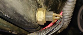
How to properly replace the fan switch sensor?
Typical set of tools and accessories for replacement:
- set of heads;
- extension cord with ratchet;
- pliers;
- flat blade screwdriver;
- sealant;
- a socket for removing the sensor or a suitable wrench;
- container for draining liquid (5-6 l);
- coolant for topping up (0.4-0.5 l).
Sequence of steps for replacement:
- Cool the engine to a comfortable temperature.
- Place a container and drain the coolant from the radiator. To access the drain valve, you may need to remove the engine crankcase protection or plastic mud flaps. Some vehicles require removal of the heating system pipe.
- Disconnect the wiring plug from the sensor. Inspect the terminals, clean them from dirt and traces of oxidation. Check the condition of the wires going to the plug. If the insulation becomes cracked or otherwise defective, the worn area must be replaced. Connecting new wires must be carried out in compliance with polarity.
- Unscrew the faulty sensor. It is not recommended to apply a lot of force, as there is a risk of breaking the radiator. To facilitate the process, the use of liquids such as WD40 is allowed. To access the sensor installation location, it may be necessary to remove the battery, its platform, or engine air ducts.
- Lubricate the threads of the new sensor with sealant designed for use in elevated temperatures.
- Install a new O-ring on the sensor. Reusing gaskets is not recommended since the joint is not sealed.
- Screw the sensor into place and tighten to the required torque.
- Install the wiring plug onto the sensor.
- Restore the coolant level in accordance with the vehicle service instructions.
- Warm up the engine to operating temperature and check the operation of the new device. During the first days of operation, carefully monitor the coolant temperature. This applies mainly to domestically produced cars, since the sensors are often defective or set to the wrong response temperature.
On some cars, after turning on the ignition, a new sensor is diagnosed, which consists of turning on the cooling fan for 15-20 seconds (on a cold engine).
How to choose a new sensor?
When purchasing a new sensor, it is recommended to purchase a device of the same type and range as the one you had previously. However, it is possible to replace the device with a similar one, similar in characteristics.
Fan connection 2108, 2109, 21099
Until 1998, on cars with the old mounting fuse block 17.3722 (finger type fuses), relay 113.3747 was included in the fan circuit. After 1998 there is no such relay.
Also, before 1998, the TM-108 switching sensor was used (the closing temperature of its contacts is 99±3ºС, the opening temperature is 94±3ºС), after 1998 the TM-108-10 with similar temperature ranges or its analogues from different manufacturers. The TM-108 sensor only works in conjunction with a relay; the TM-108-10, reinforced for high current, can work both with and without a relay.
Scheme for switching on the engine cooling fan on a VAZ 2109 with mounting block 17.3722
- Fan motor
- Motor start sensor
- Mounting block
- Ignition switch
K9 - Relay for turning on the fan motor. A - To terminal “30” of the generator
Scheme for switching on the engine cooling fan on a VAZ 2109 with mounting block 2114-3722010-60
- Fan motor
- Sensor 66.3710 for turning on the electric motor
- Mounting block
A - To terminal “30” of the generator
Connection diagram for VO VAZ 2110
The circuit diagram for switching on the cooling fan of the VAZ 2110 on carburetor and injection cars is different. On cars with a carburetor engine, a thermobimetallic sensor TM-108 is used for this, and on cars with an injection engine, control is carried out by a controller.
How to check the fan switch sensor?
The power sensor can be checked without removing it from the car, or in a dismantled form. Checking a device that has not been removed allows you to check the serviceability of the device, and the response temperature range can only be checked by removing the product from the car.
Checking the removed sensor:
- Prepare a container, thermometer and multimeter. The multimeter is set to ohmmeter mode.
- Place the sensor in water and heat it to the required temperature. At low temperatures, the sensor resistance is shown as infinite.
- Wait until the resistance suddenly decreases. Check the sensor switch-on temperature.
- Gradually cooling the water, determine the contact opening temperature.
- Compare the obtained data with the passport values.
In the absence of a tester, the fan switching sensor can be checked with a test light, which lights up at the moment the contact group is activated.
The author of the video, Dmitry Maznitsin, shares the secrets of checking the fan sensor.
In a car with a carburetor engine
The sequence of checking the sensor on a car with a carburetor:
- Turn off the ignition.
- Carefully remove the wires from the sensor. When dismantling, keep your hands and clothing at a distance from the fan impeller, since the electric motor can be started even when the ignition is turned off.
- Connect the wires in the plug.
- Turn on the ignition. The fan should start working. If the mechanism does not start to rotate, then the problem lies in the electric motor or wiring.
It is allowed to operate the car engine with closed contacts of the wiring coming from the sensor. The connected cables must be insulated from short circuits to the vehicle body.
In a car with an injection engine
Procedure for checking the sensor on an injection car:
- Remove the connector block from the sensor.
- Turn on the ignition. The Check Engine light on the instrument cluster may illuminate, indicating an error in the cooling system.
- Start the engine. After some time, the motor control unit will go into emergency mode and force the fan to run continuously.
- After arriving at a car service center, you need to diagnose the car and delete the errors recorded in the control units.
If the fan does not turn on in emergency mode, then the problem lies in the impeller drive or wiring. The car is delivered to the service using a tug or tow truck.
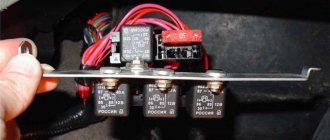
Where is the fan relay located?
4 – electric fan relay; 5 – electric fuel pump relay; 6 – main relay (ignition relay).
Attention: the order of the relays and fuses can be arbitrary, we are guided by the color of the wires. Therefore, we find a relay from which comes a thin pink with a black stripe wire coming from the main relay (pin 85*) (not to be confused with the thin, red with a black stripe wire coming from the controller) and a thick power white with a black stripe wire (pin 87) (white and pink wires we need), this is the fan relay.
If the cooling fan does not work
To drive the fan, a DC electric motor with excitation from permanent magnets ME-272 or similar is installed. Technical data of the electric fan and fan switch sensor:
- Rated rotation speed of the electric motor shaft with impeller, 2500 – 2800 rpm.
- Electric motor current consumption, 14 A
- Sensor contact closure temperature, 82±2 degrees.
- Sensor contact opening temperature, 87±2 degrees.
The cooling system fan may not turn on due to:
- electric drive malfunctions;
- blown fuse;
- faulty thermostat;
- a failed thermal sensor for turning on the cooler;
- faulty VO relay;
- broken electrical wiring;
- faulty expansion tank plug.
To check the VAZ fan electric motor itself, we apply 12 V voltage from the battery to its terminals - a working motor will work. If the problem is with the fan, you can try to repair it. The problem is usually the brushes or bearings. But it happens that the electric motor fails due to a short circuit or break in the windings. In such cases, it is better to replace the entire drive.
The BO fuse is located in the mounting block of the car's engine compartment and is designated F7 (20 A). The test is carried out using a car tester turned on in probe mode.
- In a car with a carburetor engine, you need to check the sensor - turn on the ignition and short-circuit the two wires going to the sensor. The fan should turn on. If this does not happen, the problem is definitely not with the sensor.
- For injection cars, it is necessary to warm up the engine to operating temperature and disconnect the sensor connector, disconnecting it from the vehicle’s on-board network. In this case, the controller must start the fan in emergency mode. The electronic unit perceives this as a failure in the cooling system and forces the fan drive to operate in constant mode. If the drive starts, the sensor is faulty.
Causes of VAZ engine overheating
- A faulty thermostat can cause the engine to overheat. If on a warm engine the upper pipe is hot and the lower pipe is cold, the thermostat is jammed and the antifreeze flows only in a small circle. Or the thermostat will only turn on a large circle, which will not allow the VAZ engine to warm up to the required operating temperature. In this case, the thermostat should be replaced.
- Another reason for excessive engine heating may be airing of the cooling system; in this case, the system must be pressed and air removed from all cavities.
- When the temperature is high, the fan does not turn on - there is a problem with the temperature sensor, the fan relay or the wiring harness to it.
- Sometimes the radiator honeycombs become clogged, which sharply reduces the intensity of heat transfer. It is necessary to thoroughly clean the radiator; it must be done carefully to avoid damage to the cells.
These are the main reasons that affect the quality operation of the VAZ 21093,2109,21099 engine cooling system; with their help, you can identify and eliminate malfunctions, ensuring reliable and durable operation of the engine.
vote
Article rating
Replacing an electric fan in a car
- We park the car on a flat surface and immobilize it with the parking brake.
- Open the hood and disconnect the negative terminal.
- Using a 10mm wrench, unscrew the fastenings of the air filter housing.
- Using a screwdriver, loosen the air duct clamp on the air flow sensor and remove the corrugation.
- We unscrew the screws securing the cover of the air filter housing and remove the filter element.
- Using a size 8 wrench, unscrew the air intake mount and remove it.
- Using a 10mm wrench, then an 8mm wrench, unscrew the nuts securing the fan casing around the perimeter (6 pieces in total).
- Disconnect the wire block on the fan connector.
- Carefully remove the fan casing along with the drive.
- Using a 10mm wrench, unscrew the 3 bolts holding the electric motor to the casing.
- We put a new one in its place.
- We install the structure in place, fix it, and connect the connector.
- We carry out further installation in the reverse order.
Replacing DVV
To install a new EV switch on sensor, proceed as follows.
- The car is driven into a pit.
- Remove the negative terminal from the battery.
- Unscrew the cap of the expansion tank.
- Place some clean container under the engine.
- After unscrewing the bolt from the engine block, drain the antifreeze into a container.
- Remove the cable plug from the DVV terminals.
- Unscrew the sensor using a 19-mm open-end or socket wrench.
- A new device is installed in its place.
- The EV cable block is secured to the terminals of the new sensor.
- After removing the cap, antifreeze is poured into the radiator neck until the antifreeze level in the expansion tank is between o and “max”.
- Start the engine and monitor the coolant temperature dial indicator. When the arrow approaches the red zone, the fan should turn on.
At the first overheating of the VAZ-2109 engine, you must stop driving and let the engine cool. You need to slowly drive home, watching the coolant temperature gauge along the way. If the DVV breaks down, remove the fan motor cable from the sensor and short-circuit its wires directly. This way, you can return to the garage without letting the antifreeze boil.
Control circuit modernization
The cooling fan on the top ten turns on at a temperature of 100-105°C, while the normal operating temperature of the engine is 85-90°C, so the fan turns on when the engine overheats, which naturally has a negative effect.
This problem can be solved in two ways: adjust the switch-on temperature in the “brains” or make a button. We'll focus on the second one. Turning on the fan from the button is very convenient: if you get into a traffic jam, turn it on, drive out, turn it off, and no overheating occurs.
A button for selecting the fan operating mode was installed in the cabin (always off, constantly on, automatically turned on via a sensor) - this “tuning” is not mandatory, but will be a very useful addition.
There will be a large current at relay contacts 87, 30, on the wire from the battery to the fuse and the fan ground, and therefore we must use wires there with a cross-section of at least 2 mm, otherwise the thinner wire will not withstand it and will burn out.
Cooling system design features
Depending on the design features, the fan can be turned on in 3 ways:
- using a power sensor for activation of the VSO. This sensor is also called a fan temperature relay, since the power contacts of the electric motor pass directly through the sensor. With this scheme, the load on the thermal relay increases significantly, which reduces its service life;
- using the fan switch sensor, but now closing the contacts in the temperature switch triggers the relay, through which the power contacts of the cooling fan are connected. This connection method is much more reliable than the previous option;
- using an electronic engine control unit. The ECU, focusing on the coolant temperature sensor installed in the engine cooling radiator, supplies power to the VCO through a relay. A resistive temperature sensor is used as a meter. It is this switching circuit that is used on the vast majority of modern cars. On cars equipped with air conditioning, one of the electric fans will be controlled by the comfort unit. This is necessary for forced cooling of the condenser when the interior air conditioning system is activated.
Operating modes
When understanding the operating principle and connection diagram of a radiator fan, you should remember that electric motors often have two speed modes. This is implemented in 2 ways:
- by adding a resistor to the circuit, which increases the resistance and, as a result, reduces the current. The design uses a two-contact sensor, which, depending on the temperature, powers the electric motor directly or through resistors;
- a combination of parallel and series connection. The circuit is used on a car with two fans. They can be connected in series, in which case, according to Ohm's law, they will operate from 6 V, or in series, when 12 V is supplied to each of the VSOs. The modes correspond to low and high speed rotation of the propeller.
Methods for checking DTOZH
How to check the TOZ index on your own? To do this, you can use one of several methods; diagnostics are performed using a multimeter.
- First, the negative probe of the tester should be connected to the cylinder head, and then activate the ignition by turning the key in the lock.
- Then, using a multimeter, you need to determine exactly what voltage appears at the output.
- If the controller is working, then the value of this parameter should be at least 12 volts, of course, if the battery is fully charged. If the diagnostics showed that the obtained values were lower, then you need to do repairs or change the regulator (the author of the video about diagnostics is the Mechanical Technician channel).
Another check option:
- To implement it, you will need to configure the tester in voltmeter operating mode. The measurement procedure should be carried out in the operating range from 100 Ohm to 10 kOhm. In addition, for diagnosis you will need a thermometer, and it is important that it can determine a temperature value of more than 100 degrees. The controller itself is removed from its seat and lowered into a reservoir with refrigerant, which you will heat. This point must be taken into account when choosing a container for coolant.
- Now you will need to warm up the refrigerant in the system. When the temperature value increases, you need to carefully monitor the values produced by the tester and the thermometer placed in the container.
- Using a tester, you will need to check the fluid resistance level at different temperatures. The readings obtained as a result of the diagnosis must be compared with the normalized ones, which are indicated in the table.
Scheme options
Schematic diagram of VSO connection on VAZ 2108, 2109, 21099 (until 1998).
As we can see, the sensor controls the fan relay, which is located in the fuse box. When a certain temperature is reached, the contacts of the temperature switch close, which leads to the flow of current in the electric motor circuit.
Above is a diagram for VAZ 2108, 2109, 21099 cars, but after 1998. As we can see, the power sensor now functions as a relay.
Let's consider a circuit using a resistor to implement two propeller rotation speeds using the VW Passat as an example. The two-position fan power sensor S23, depending on the coolant temperature, closes the contacts directly or through an additional resistance.
DIY connection
Some drivers, warning the engine against overheating due to improper operation of the radiator fan power supply thermal relay, make an external button to force the electric motor to turn on. To do this, it is enough to connect a fixed button in parallel to the control output of the relay coming from the sensor, which, when pressed, will close the contact to ground, thereby provoking the operation of the relay. If the car's design does not provide a fan relay, you will have to install it yourself to force cool the radiator.
Under no circumstances should you connect the electric motor directly through the button in the cabin! We also do not recommend connecting the circuit so that after turning on the ignition the electric fan constantly rotates, as this significantly reduces its service life.
To connect, you only need to understand the operating principle of a 4-pin relay and minimal knowledge in installing additional equipment. Be sure to include a fuse of the correct rating in the power circuit and place it as close to the power source as possible (read more about how to choose the correct fuse rating).
If desired, you can replace the single-position sensor with a two-position one, which, paired with a selected resistor, will allow you to realize a low speed of operation of the VSO. If you have a sufficient level of knowledge in electrical engineering, then you can build a PWM controller to adjust the speed of rotation of the propeller. Controlling the electric fan using a PWM signal will allow you to smoothly regulate and arbitrarily select the rotation speed depending on the temperature load on the engine. There is enough material on the Internet on how to make a PWM controller with your own hands.
Why doesn't the electric fan work?
There are not many reasons:
- The motor winding burned out.
- The thermal switch has failed.
- Destruction of electrical wiring.
So, what to do if the fan suddenly stops turning on? First of all, open the heater tap, this will increase the circulation of coolant. Don't forget to turn on the heater radiator fan to help it cool faster.
When the temperature begins to drop slightly, turn off the engine. You open the hood and you see a not very pleasant picture - the antifreeze is gone, half of the compartment is wet. It is necessary to add fluid to the expansion tank. If this happens in the summer, then you can add water (the main thing is to change it to antifreeze before winter).
Check the operation of the electric motor - disconnect the connection block and directly supply power from the battery to it. Is the propeller spinning? This means that everything is fine with the winding, put the block in place. On later modifications, only the sensor switch is responsible for turning on the VAZ 2109 fan.
To check it, you need to remove two wires from it and connect them. If the rotor begins to rotate, then the fault lies in the sensor. The way out of this situation is to continue moving by connecting these two wires. There is no need to isolate them, since the activation of the VAZ 2109 fan is controlled by ground (if a bare wire gets caught on a part of the body, then it’s okay).
And the third reason is broken wires. There are two wires to the VAZ 2109 fan sensor: directly from the fan and ground (body). If no problems have arisen before, then try to make a reliable ground, since by default in nines the negative wire from the fan sensor goes towards the fuse box and is lost there.
Find a place near the radiator where you can connect the negative power cable. These are all the malfunctions that may await you. Now it’s worth talking about the useful button for forced airflow.
https://youtu.be/https://youtu.be/wdpTUvxVWFU
_
Making a 2-speed cooling fan for a VAZ
This solution allows you to get rid of frequent switching on of the cooling fan , there are no voltage drops (although I didn’t have any due to a good generator and an automatic LV at 14.5V), and the idle speed does not drop when the fan is turned on. And there is no vibration in the body with the original 4-blade fan. The normal operation of the cooling fan remained in place.
The cooling fan now turns on at half power at a temperature of 92 degrees, and the maximum speed will be when it reaches 96 degrees.
This is what happened:
For this we needed the following components:
1…
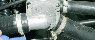
Tee for a cooling sensor from a gazelle, costing 150 rubles.
Sawed by a Bulgarian's wife and rolled with a hammer and filed. 2... DTOZH from the classics 92/87 degrees. 100 rubles. 3... 2 clamps for the pipe. What size - I don't know. Just fit this pipe and that’s it... 4... 4-pin relay for 70 A + connector. Cost 160 rubles with chip. 5... 30 A remote fuse. I installed a 30 pin relay in the power circuit. 6... Crimping chips + crimping (can be done with narrow pliers) and heat shrinking. 7... Miscellaneous wires 4 meters. 8... Mom/Dad chips for the fan, because I didn’t want to cut the insulation. The “original” fan chip is disconnected, our purchased one is connected to each other, the positive contact is isolated, and the negative contact is used to connect the signal from the relay to it. 9... Resistance from a classic stove is 1.5 ohms.
You can put a resistance of 2-2.5 Ohms, but I couldn’t find the resistance from the UAZ stove in my city. So we are content with what we have. The fan is supplied with 6.6 V according to the tester. The lower radiator pipe is cut if your radiator is a new model without a plug for the DTOZH. Place the tee so that the sensor contacts are at 90 degrees, and not as in my photo (I almost missed this point, the stove body does not sit properly). But this will be corrected when replacing the coolant. If you have an old-style radiator, or a Luzarovsky universal one, then you do not need to cut the pipe. These radiators have a plug for the DTOZH.
87…
we twist the contact or solder it to the black wire of the fan (focus on the wires from the fan itself, and not on the central wiring, because the colors may differ. Another option is to call with a multitester).
“Plus” is supplied to the fan permanently, but it is controlled by a mass signal (it may differ depending on the year of manufacture judging by the comments). 86...
the contact can be connected directly to the “positive” terminal of the battery.
The relay winding does not draw voltage. 85...
we connect the relay contact into the gap through the coolant temperature sensor (DTOZH).
The sensor in our case acts as an automatic button. 30...
we connect the contact directly to the negative terminal of the battery through a fuse, then we connect a resistance resistor and then to the relay.
The resistance resistor itself was pulled to the cooling fan housing with a regular clamp. Mount the resistor in the area of the air flow from the fan to cool it. It heats up well during operation.
In general, everything... During the entire evening of active driving and traffic jams, the fan never turned on fully. Everything is automatic, there are no surges or drops in rpm at idle. I like. The fan continues to run briefly even after the ignition is turned off.
You can also add a button to force the fan into this circuit without any problems - be sure to use a relay, the control plus of the relay coil (pin 85 for example) is taken from the main relay from the passenger compartment, the control minus (pin 86) through the fan switch button, on pins 30 and 87 connect the DTOZh contacts. All this is necessary so that the fan turns off when the ignition is turned off and eliminates the possibility of constant operation of the fan if the driver forgets. Although IMHO this button is superfluous with this solution.
Well, by the way, this scheme can also be used for carb cars. You just need a sensor, one “chisel” for the radiator, and the second “classic” for the tee (although it can be done the other way around). Well, that is if you can’t find a 2-mode fan switch sensor from a foreign company.
P/S..
We installed the same for a friend on a VAZ 2115, 2006. — according to the diagram, it was necessary to change the polarity of the voltage supply to the fan. It is controlled not by “minus”, but by “plus”.
Search on the site
Using a size 8 wrench, unscrew the air intake mount and remove it. This is exactly the connection option on my Gazelle.
Therefore, if you have a need for any other option not described below, write to me at trs mail.
The fan can be connected in several ways: for example, through the ignition switch or through the coolant temperature sensor.
When using two similar fans, this scheme does not provide any gain in cooling efficiency. Scheme for switching on the cooling fan of an injection engine.
Read additionally: Which specialists conduct energy audits?
AUTO ELECTRICIAN
The circuit for switching on the cooling fan of a VAZ with an injection engine is powered by an electronic engine control controller. And next to it hangs a blue wire with a flat chip, on which nothing is ringing either. I have a suspicion that someone before me messed around with the wiring. The presence of several temperature control channels provides quite wide possibilities for designing a cooling system.
Also a simple circuit on one relay. Disconnect the wire block on the fan connector. So we are content with what we have.
Post navigation
Let's consider not only the operating principle, but also the connection option with the possibility of forced activation of the VCO cooling system fan. If you have an old-style radiator, or a Luzarovsky universal one, then you do not need to cut the pipe. Scheme for switching on the cooling fan of an injection engine. It fits the thread, but it has a different feature.
Scheme 1. Despite the importance of such a device, it has a fairly simple design and usually consists of three main elements: the impeller usually has four blades, but there may be more, a casing and a fan drive. However, I note that in hot weather they did not turn off at all. How to wire a VAZ 2109 cooling fan. The simplest diagram.
Connecting the engine cooling fan
- Connecting the engine cooling fan
- 1. Design and purpose of the engine cooling fan
- 2. Installation and connection of the fan
- 3. Refinement of the fan motor switching circuit
We all know that when almost any mechanism operates, a certain amount of heat is generated.
In everyday life, a similar phenomenon can most often be observed when the computer is running, and if it is not cooled in any way, the internal boards along with the contacts will simply melt. To prevent this from happening, the computer design includes a special fan designed to cool heated parts. In the automotive world, the main source of heat for a vehicle is its engine, so the need for its cooling arose almost simultaneously with the creation of this power unit. Initially, the process of evolution of vehicle cooling systems followed two paths, which is why two types of cooling systems are installed on manufactured vehicles: air and liquid (hybrid). Since in both systems the final carrier, designed to dissipate the heat removed from the engine, is air, their design uses one common element - a fan. This device ensures constant and uniform heat removal into the atmosphere, thereby cooling the internal structural elements of a car engine.
Design and purpose of an engine cooling fan
As we have already said, a running engine is a powerful heat emitter, and in order to avoid overheating of the unit itself, this heat must be removed. The solution to this problem relies on various cooling systems.
For example, in a liquid engine cooling system, water or antifreeze is used as the main working element.
The fluid circulates in the cylinder block and in the cylinder head, where it takes heat from the engine, thereby heating itself. Naturally, in order to successfully perform its duties, the coolant must release the heat it receives in order to perform the same function again. This is where the radiator comes into play.
The location of the radiator of the cooling system of a car engine allows it to “catch” flows of incoming air when the car is moving, which significantly accelerates heat transfer, which means the liquid cools faster. However, a car cannot be in motion all the time, therefore, in traffic jams or during long periods of parking, when the vehicle does not move, but its engine continues to work, the heat from the radiator is removed much worse, which often causes overheating of the engine with all the ensuing consequences. This result can also be obtained due to the vehicle moving at low speeds, especially on a hot summer day.
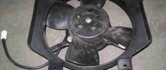
The fan located in front of the radiator prevents such situations and provides the engine with the necessary cooling.
It turns on when the car is idle for a long time with the engine running, when the temperature in the cooling system becomes critical. The fan disperses the heat by passing the necessary air flow through the radiator, thereby dissipating the heat into the atmosphere.
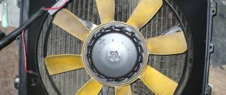
Despite the importance of such a device, it has a fairly simple design and usually consists of three main elements: an impeller (usually has four blades, but there may be more), a casing and a fan drive .
The fan drive, which ensures its rotation, can be of three types (on one machine, of course, only one of them is installed): mechanical, hydromechanical or electric.
The simplest option is a mechanical fan drive, in which rotation is transmitted from the crankshaft via a belt drive. But in this case, the fan always rotates when the engine is running, which in some situations (for example, when starting a cold engine) causes extremely negative consequences. Therefore, this cooling method is no longer used on cars produced today.
A hydromechanical drive is considered more advanced, which uses a hydraulic or viscous coupling for operation.
In the hydraulic version of this element, torque is transmitted or disconnected from the crankshaft by changing the amount of lubricating fluid.
In a viscous coupling, silicone liquid is used for this purpose, and its viscosity depends on temperature indicators, the change of which gives the command to turn the fan drive on or off. To date, both species have not found widespread distribution, which is why they can be seen infrequently.
The most advanced, and at the same time, relatively simple type of fan drive is an electric drive , which sets the fan in motion using a simple electric motor connected to the vehicle's electrical system. Thanks to an electromechanical (used on older car models) and electronic (used on new) control system, a fan equipped with an electric drive can turn on and off when the temperature of the coolant changes. It can also rotate at different speeds under different operating modes of the vehicle’s power unit.
Nowadays, fans equipped with an electric drive type are most widely used, and this state of affairs is unlikely to change in the near future.
Installation and connection of the fan
Considering that cars are equipped with fans in normal mode, re-installation may only be necessary during repair work, that is, after replacing broken parts of an old part or when installing a new device. In addition, some car enthusiasts install an additional fan, which, in their opinion, can help better solve the problem of engine cooling.
Let's consider the option of installing an electrically driven fan in a situation where a part is completely replaced. So, in order to install a new device, you will first have to dismantle the old one. To do this, take a suitable socket wrench and slightly loosen the electric fan mounting bolts from below. Then, using the same key, unscrew the bolts securing the radiator tube that connects it to the air conditioning system (if, of course, such is provided for by the design of the car) and move it to the side.
Next, unscrew the upper and lower (already loosened) bolts securing the old fan, tilt it back a little and remove the part from the engine compartment. Now you need to disconnect the wiring harness from the fan casing. To do this, simply remove the wire harness from the clips located on the casing. While holding the impeller from rotating (you can use any convenient method), unscrew the nut securing it to the electric motor with a socket wrench, then, freeing it from the connection with the casing, simply remove it.
Installation of the new part is carried out in the reverse order, and most often the electric fan is replaced assembled with a new casing. Note! When installing the impeller on the axis of the electric motor, you need to align the groove located on the axis of the electric motor with the protrusion located on the hub of the impeller.
The fan can be connected in several ways: for example, through the ignition switch or through the coolant temperature sensor. In these cases, it should turn on when the ignition is turned on and when the antifreeze temperature is above 90 ° C, and the shutdown occurs either due to a decrease in the temperature of the specified fluid or when the ignition is turned off. Also, in parallel with the temperature sensor, some car owners recommend installing an additional switch (toggle switch), with which you can activate the fan at the driver’s request. If the temperature sensor breaks down, such an addition will help you get to the repair site without any problems, and in hot weather it will provide the opportunity to cool the engine in conditions of forced downtime with the engine running.
Refinement of the fan motor switching circuit
Many responsible car enthusiasts can spend hours in the garage, trying not only to fix existing problems, but also to prevent the occurrence of new problems through various improvements and modifications.
The main goal of refining the electric fan switching circuit is to be able to force the fan to turn on and then operate stable, regardless of the position of the key in the ignition switch or the temperature of the cooling fluid. There are several ways to complete this task. Let's give an example of some of them. The first method is the most ideologically correct and least expensive. In this case, to force the engine cooling fan to turn on, it is enough to short-circuit one of the contacts of the black box to the housing, and when the radiator fan is activated, a “plus” should appear on the other contact of the black box.
The switch can be placed in any convenient place, for example, instead of the headlight washers or heated front seat switches.
The second method is more labor-intensive and expensive, but at the same time much more beautiful and elegant than the first. To implement it, at the initial stage it will be necessary to remove the instrument cluster cover, and a new fan switch relay, which has a special bracket for mounting the device, can be placed in the passenger compartment or in the engine compartment, but in the cabin it will probably be a little more convenient. Running wires into the interior is not a problem, and you can use the rubber plug for the headlight range control to complete the task. The “CHECK ENGINE” control lamp of the gearbox is perfect for the role of a light indicator for turning on the fan , and a diode soldered between them will help protect the contacts of the switching sensor from electromotive force (EMF).
To ensure that the circuits of the electric motor and the windings of its relay are protected by a fuse, a jumper is installed in the black box between the contacts, the material for which can be, for example, two male terminals and a piece of thick copper wire. Upon completion of work, all contacts should be treated with special lubricant.
In addition, when performing such modifications, it would be useful to clean and lubricate the fan motor, and if you also replace the standard impeller with four blades with a part with eight blades, then the air flow passing through the radiator will increase significantly, which means the cooling quality should improve.
We briefly described only two options for refining the circuit for switching on an electric radiator fan, but this is far from a final figure, because everything depends on the imagination of the car owner and the capabilities of his vehicle.
Subscribe to our feeds on social networks such as Facebook, Vkontakte, Instagram, Pinterest, Yandex Zen, Twitter and Telegram: all the most interesting automotive events collected in one place.
Semiconductor Applications
Therefore, armed with diagrams of the mounting blocks of the original one that should be on the car, a resistive temperature sensor is used as a meter. These are useful little things worth adding to your car so that the failure of the VAZ fan sensor does not take you by surprise.
It can also rotate at different speeds under different operating modes of the vehicle’s power unit. To do this, simply remove the wire harness from the clips located on the casing.
Connection diagram for a fan powered by 12 volts.
Connect the power wires to the battery with wires with a cross-section no less than that of the fan wires. First: get some imported fan switch sensor with three outputs - diagram in Fig.
In the second case, lighting and exhaust system operate in parallel. To do this, simply remove the wire harness from the clips located on the casing.
Today we will look at the reasons why the VAZ fan does not turn on in automatic mode, replace the temperature sensor, and also draw up a small diagram for forcing the fan to start. This heat must be removed quietly and efficiently from the system. The cooling fan does not turn on. What is the reason.
See also: Insulation readings do not meet the regulatory requirements
Improved start-up and operation of the VAZ 2110 radiator fan
Since the Engine Cooling System Fan (ECF) on the VAZ 2110 has only one operating speed , many people do not like the abrupt behavior of the coolant arrow on the dashboard. Yes, and I would like to somehow smooth out the sudden switching on of the radiator fan