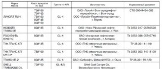
Diagnostic methods
As of 2022, there are two popular ways to find and decipher errors in a Lada Kalina computer of both generations.
Self-diagnosis
The easiest and most common way to diagnose error codes on a VAZ Kalina is to search using the on-board network. The procedure looks like this.
- Insert the key into the lock cylinder.
- Next, hold down the RESET key and, without releasing it, turn on the ignition
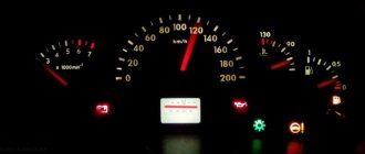
- In this case, the device will automatically switch to diagnostic mode. At the same time, all the indications will light up, and the instrument arrows will make a full circle. You should pay attention to the arrows and indicators - if any diode does not light up, you need to check the device for which the element is responsible.
- On the right steering column lever there is a button for scrolling through the options - you need to scroll to the required position (error codes).
- Next, the display will show the general error number; to reset the index, you need to hold RES for three seconds.
Note! The indicated sequence is relevant for Lada Kalina of the first and second modifications.
The position of the error codes will show one of the indices on the display:
- “2” – there is a surge in the BS power supply – a possible short circuit in the wiring;
- “3” – rupture of lines, or failure of the float inside the gas tank;
- error 4 Lada Kalina says that the coolant temperature sensor is broken or malfunctioning;
- “5” – the thermometer has gone astray, the element may be damaged or the circuit may be broken;
- “6” – exceeding the maximum permissible temperature of the internal combustion engine block, while the acoustic alarm is working;
- “7” – exceeding the permissible pressure thresholds inside the oil line;
- “8” - on a Lada Kalina car, error 8 appears when there is a malfunction of the calipers or a breakdown in the hydraulic drive line;
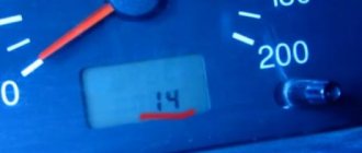
- “9” – critical voltage drop in the battery;
- “E” – incorrect reading or display of the EEPROM information module.
To return to the starting part, it is enough to hold RES for 30 s. The disadvantage of this method is minimal accuracy - the procedure shows in which direction to look for a breakdown, but not a specific node. So, it is possible to understand exactly where the failure occurred only by the following method.
Check via external system
To perform the procedure, you will need to connect a PC to the diagnostic output of the machine. The terminal is located under the dashboard on the right (location may vary depending on the batch and year of manufacture). After pairing is established, standard codes begin to appear in the software window. Markings are required for versatility - the car is also supplied for export, which would require re-flashing the BC for each language - this is not at all convenient and requires the investment of large resources and time, that’s why it is so. When you activate the program, five-digit codes appear on the screen. Each element speaks about a unique indicator. First letter of the index:
- P – electrical defect;
- C – the problem is in the chassis electrical circuit;
- B is the root of evil in the interior space of the cabin;
- U – loss of synchronization of several circuits.
The first element of the digital combination is indicated next:
- 0 – OBD 2;
- 1 and 2 – standard enterprise code (it is not known for certain what this means);
- 3 – spare system.
These indicators indicate a faulty unit. Next in order is the number of the on-board circuit where the defect is located:
- 0 – exhaust installation and muffler;
- 1 – supply of oxygen inside the internal combustion engine;
- 2 – gasoline supply;
- 4 – secondary control of the installation;
- 5 – incorrect setting of crankshaft speed;
- 7 and 8 – transmission units, drive units, axles.
The last part of the encoding indicates directly the defect number in order.
Getting ready to replace the resonator
After some time of operation, every owner of a practical Lada Kalina is faced with the need to replace components of the exhaust circuit; a resonator needs to be replaced, and less often, a muffler needs to be replaced. Of course, no one has canceled the option of performing the repair procedure in a car service center, but the resonator is one of those products that are available for manual replacement.
To perform the entire list of repair operations, the owner does not need to use special tools and devices.
It will be enough to acquire:
- WD-40 penetrating agent, required for treating corroding joint areas of the resonator and its fasteners;
- a pair of keys of identical standard size (on “13”), only one of them will need a socket, and as the second you need to use a head complete with a wrench;
- with a hammer.
The main reason prompting the owner of a Lada Kalina to start replacing the resonator is progressive corrosion. Here it will be necessary to replace not only the exhaust system component itself, but also its fasteners (clamps), since they are also subject to intense corrosion and oxidation due to their location.
It is also recommended to replace the rubber suspensions of the resonator to the body, since over time they harden and crack, and therefore, gusts are possible and the exhaust system stops working.
Replacing the front brake pads of Lada Granta
Errors Lada Kalina 1st generation - decoding
Important! The list can also be used for the VAZ Priora model - the digital codes are similar for both cars.
Exhaust gas outlet (0000)
- 30 – open circuit or failure of the air sensor to the catalyst;
- 31 – break in the wiring from the short circuit to the vehicle;
- 32 – a similar incident involving contact with other wires;
- 36 – open circuit of the line after the catalytic converter;
- 37 – damage to the cable winding with a short circuit to the machine body;
- 38 – wiring break with short circuit at BS.
Interruptions in the air supply to the internal combustion engine (0101)
- 102 – damage or malfunction of the mass air flow sensor;
- 103 – short circuit in the MAF wiring;
- 112/13 – failure or incorrect operation of the fuel mixture temperature sensors in the intake manifold;
- 115-116 – violation of antifreeze t° sensors – there is no cooling of the system or the main airflow is not working properly;
- 117-118 – open circuit of the coolant temperature sensor power supply/short circuit;
- 122/123 – defect in cable insulation at the TPS;
- 130/131 – error/break in DC circuit No. 1;
- 132 – short circuit of sensor No. 1 PCV;
- 133/134 – the air sensor connection is broken (sometimes it’s enough to clean the terminals and connector) or the wiring is damaged;
- 135 – malfunction of heater DK2;
- 136 – contact with the body of the DK2 highway;
- 137/138/140 – uncontrolled signal DK2 or break of the corresponding line;
- 141 – failure or interruption of heating of DC2;
- 171/172 - violation of mixture formation in the first case - depletion, for the second - excessive enrichment.
Error codes Lada Kalina 1.6 liters, indicating an uncontrolled violation in the fuel line (0200)
- 201-204 - a rupture in the control line for injectors 1-4, usually manifested by tripling or even doubling of the internal combustion engine, and the power plant may not start;
- 217 – critical temperature rise of the engine block;
- 230 - Lada Kalina error, accompanied by a drop in power or problems starting the power plant, is caused by a violation of the fuel filter relay circuit;
- 263/266/269/272 – the injector control driver has failed in sequence from No. 1 to No. 4;
- 261/267/270/264 – insulation violation of the injector control wire with a short circuit to vehicle ground for elements 1-4;
- 262/265/268/271 – similar to the previous point, only with a 12 volt touch.
Error codes Kalina 8 valves caused by incorrect ignition activation (0300)
- 300 – misfire or no spark for all pistons;
- 301/302/303/304 – similar to the previous number with clarification for each boiler sequentially;
- 325 – problems with the functioning of the DD;
- 327/328 – the mixture detonation sensor does not work correctly;
- 335/336 – failure or incorrect information is received from the DPKV unit;
- 337/338 – similarly with touching ground or other wires;
- 340 – wire break or DRF has failed;
- 342/343/346 – incorrect operation of the phase distribution indicator, possible short circuit;
- 351-354 – poor contact to the ignition coils, or damage to the wiring, for all boilers in series;
- 363 - dry pistons, no gasoline or oxygen, possible blockage or air bubble in the line.
Secondary equipment not related to the ECM (0400)
- 422 - the catalyst is clogged, excess pressure forms in the pipe, usually a complete replacement of the unit is required;
- 441 – the adsorber purge valve is faulty; cleaning or repair may be required;
- 443-445 – rupture of the purge line with the formation of a short circuit (possibly to the body);
- 480/481 – the insulation of the power cables to the main radiator fan is damaged.
Lada Kalina engine error - incorrect crankshaft speed (0500)
- 501/502 – electronic speed sensor readings are too low or high;
- 503 – contacts on the DC have oxidized, the block may be damaged;
- 505 – XO floats, you need to check the regulator;
- 506 – the engine does not hold idle speed, throttle adjustment is required;
- 507 – similar to the previous paragraph, speed float is added, TPS repair may be necessary;
- 511 – the XX regulator is faulty, perhaps it should be replaced with a new one;
- 560/562/563 – voltage surges in the vehicle network – we are looking for where the short circuit is.
Malfunction of on-board wiring lines (0600)
- 601 – failure or unstable operation of the ROM;
- 603-604 – incorrect data from internal or external RAM circuits;
- 607 – possible disruption of the detonation line;
- 615-617 – damage to the power supply wire of the auxiliary PC with a permissible short to 12 volts or ground;
- 627-629 – breakdown of the fuel pump power supply with the possibility of a short circuit;
- 645-647 – the clutch of the air conditioner pump unit is de-energized with or without a short circuit in the wiring;
- 650 is a typical Lada Kalina check error, indicating that the corresponding lamp on the dashboard has burned out:
- 654 – the electrical line of the engine speed meter is faulty;
- 685-687 – breakdown of the insulation of the main relay power cables with a possible short circuit;
- 691-692 – rupture of the wires supplying voltage to the main fan with the possibility of a short circuit to the remaining parts of the wiring.
Additional error codes on Lada Kalina (1000)
- 102/115 – disappearance of resistance or breakdown of the DC;
- 123-124 – incorrect formation of the XX mixture;
- 127-128 – similar to the previous paragraph, only at low load;
- 135 – damage to wiring DK1;
- 136-137 – incorrect mixing of air and gasoline components at low load on the internal combustion engine;
- 140 – the difference between the actual and calculated load is too large;
- 171 – potentiometer readings are underestimated;
- 172 – the opposite meaning of the above paragraph;
- 386 – incorrect data from the combustible mixture detonation channel sensor;
- 410 – break in the adsorber purge line;
- 425-426 – also with short circuit to ground or network;
- 500 – break in the fuel pump network;
- 501-502 – similar with a ground fault or 12 volts;
- 509 – critical overload of the idle speed controller;
- 513-514 – short circuit of the remote control sensor at idle speed of the internal combustion engine;
- 541 – the fuel pump has “died” or the voltage on the line has disappeared, it is also possible that a crack in the liner may form with fuel getting inside the structure;
- 570/600 – an erroneous impulse is received from the APS or there is none at all (sometimes cleaning the contact group helps);
- 602 – the ECU “shorts” at 12 volts;
- 603 – the firmware has crashed – a reboot is required;
- 606/616 – the rough road sensor indicates incorrect information (it begins to act up due to shaking on the “beautiful” asphalt);
- 612 – the ECU data was reset incorrectly, a forced reboot is required;
- 617 – the pothole indicator has died for a long time or the terminal has come loose;
- 620-622 – irreparable failure of the PROM, RAM or EEPROM blocks, respectively;
- 640 – software “glitch”;
- 689 – no problems were found during diagnostics – the encodings shown are false.
Muffler for Kalina sedan, which price is better
During operation, the engine produces certain noises, which require the installation of appropriate equipment to suppress them. The muffler for Kalina is represented by a tube, which includes the muffler itself and the resonator.
Its body is solid and sealed, it is made without welding, which indicates good protection against rust. After some period of use, the device wears out and begins to work louder. As a rule, drivers of a Lada sedan, station wagon or hatchback, whose mileage is at least 40 thousand kilometers, encounter this problem. If the part is worn out, it can be “patched”, but its complete replacement is recommended. You can do this yourself using a hammer, wrenches and lubricant.
Decoding error codes Lada Kalina 2
Most of the indexes and encodings are similar to the first generation model, before restyling. Therefore, in 80% of cases, the above list will be relevant here too. However, the new generation has acquired a large number of on-board systems that were missing on the old car, which forced the manufacturer to adjust the standard table.
Note! Below, only newly introduced or updated codes are indicated; ciphers that have not undergone changes are ignored here - you can use the existing list.
Oxygen supply to the engine (0100)
- 101 – the mass air flow sensor may be shorted, the permissible indication limits are exceeded;
- 106-108 – incorrect data from the intake manifold absolute pressure sensor;
- 130 – failure of the oxygen sensor before the catalytic converter is broken;
- 131-134 – power supply problems with the above sensor.
Supplying fuel to the cylinders (0200)
- 200 – malfunction of the fuel injector control network;
- 222-223 – incorrect indicators of the TPS network.
Ignition circuit malfunction (0300)
- 326 – critical fluctuations in the signal level from the fuel mixture detonation sensor;
- 363 – there are misfires of the mass to protect the catalyst.
Auxiliary equipment units not related to the primary circuit of electrical equipment (0400)
- 458/459 – checking the short circuit of the KPA lines to ground and 12V, respectively;
- 485 – diagnostics of the main fan supply line is required.
Throttle and brake drive VAZ Kalina 2 (0500)
- 500 – speedometer sensor network interruption;
- 501 – the above sensor is faulty;
- 503 – speed sensor indicators are floating;
- 504 – incorrect response of the brake sensor – ABS may not respond correctly;
- 505 – the XX adjustment indicator is broken or out of order;
- 506-507 – the XX regulator is jammed, accompanied by too low or high speeds;
- 522/523 – incorrect data from the oil pressure sensor inside the crankcase compartment of the internal combustion engine.
Incorrect data from the vehicle’s on-board networks (0600)
- 606 – ADC unit failed;
- 642/643 – incorrect signal from the sensor power bus;
- 660-662 – the channel length control valve is faulty or there is an open circuit with a short to 12V or ground;
- 691-692 – the power supply to the relay of the first radiator cooler is disrupted with a possible short circuit;
- 693-694 – similar, only for the second element.
Clutch line (0800)
- 830 – the switch sensor of the corresponding pedal does not respond to the ECU request; the sensor may fail or the wiring may be damaged.
Additional system error flags (1000)
- 141 – failure or damage to the DK2 heater circuit;
- 301-304 – misfires to protect the catalyst for all cylinders in series;
- 335 – incorrect position of the remote control;
- 336 – failure to synchronize the sensors and the actual throttle position;
- 384 – remote control drive control, internal combustion engine torque exceeds permissible limits;
- 385 – similar, only for the engine signal;
- 386 – the line indicating the presence of detonation of the mixture fails;
- 387 – violation of synchronization of the injection moment with the position of the remote control;
- 388 – TPS does not respond correctly to pressing the gas pedal;
- 389 – also only with exceeding the power plant speed thresholds;
- 390 – the throttle valve does not respond to the ECU request;
- 410/425/426 – malfunction of the canister purge valve circuit with a short circuit to ground or 12 volts;
- 513/514 – open circuit of the XX sensor network with a short circuit;
- 545 – synchronization failure or slow response of the remote control to the TPS pulse;
- 558 – wear or breakage of the throttle spring;
- 559 – remote control drive is faulty;
- 570 – immobilizer circuit open;
- 578 – malfunction or jamming of the remote control drive;
- 600 – no response from the immobilizer;
- 602 – power supply to the on-board network is lost, it may be necessary to tighten the battery terminals;
- 603 – EEPROM failure;
- 689 – error memory data is displayed incorrectly.
Peripheral BU system (2000)
- 70-71 – the channel size diagnostic valve is faulty (jammed);
- 100 – break in the PDZ line;
- 101 – similar value to the previous paragraph;
- 102/103 – short circuit of the remote control control line;
- 105 – control unit failure;
- 122/123 – incorrect pedal position signal;
- 127/128 – similar to the above code;
- 187/188 – excessively rich or lean mixture at idle;
- 135 – sensors A and B, designed to control the position of the remote control, do not respond correctly;
- 138 – similar value for the corresponding accelerator lever position sensors;
- 176 – throttle drive position failure;
- 178 – complete failure of adaptation of the above block;
- 187/188 – incorrect mixture formation;
- 270/271 – lack of reaction of DK2 to enrichment or depletion of the mixture after the catalyst;
- 301/304/307/310 – short circuit of the ignition coil for all cylinders, respectively;
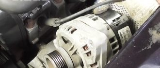
- 500/501 – incorrect generator power readings.
Lada Kalina errors, interpretation for automatic transmission (P0000)
- 720 – failure of the output shaft rotation sensor;
- 717 – turbine rotation sensor;
- 705-706 – no selector signal or multiple values;
- 973/974 – solenoid on/off, open circuit or short circuit to ground;
- 962/963 - the same element responsible for pressure - there is a break or short circuit;
- 740/743 – LOCK UP SOL open or closed;
- 17AB/AA – L/C SOL;
- 17АЭ/AD – 2-4/B SOL;
- 17B1/B0 – H/C and L and R/B;
- 1735-1738 – the 1st-4th gear lock is closed, respectively;
- 744/1744 – LU CLUTCH;
- 731-734 – incorrect ratio for positions 1-4;
- 17A0-A4 – reverse and forward gears do not work alternately in accordance with the last digit of the code;
- 711-713 – network malfunction or DTM failure;
- 863 – connection failure with the diagnostic computer;
- 062F – memory error;
- 1701 – main controller power failure.
Malfunction of data transmission from the BC to the diagnostic unit (U0000)
- 1 – test tire is broken;
- 9 – similar value with a short circuit in the line;
- 73 – connect the CAN connector;
- 0100 – connect the engine check connector;
- 305 – software incompatibility with EBKK.
Important! The specified data is similar to the VAZ Granta car.
Exhaust system
Exhaust gases are discharged from the engine through exhaust pipe 1, Figure 22, of the muffler with neutralizer assembly, additional muffler 8 and main muffler 10. A sealing gasket 20 is installed between the flanges of the exhaust pipe and the additional muffler. There is a vibration compensator on the pipe of the additional muffler. The pipes of the main and additional mufflers are connected to each other by flared ends using a clamp 13 with an intermediate ring 14. The gas exhaust system is attached to the car body using muffler suspension cushions 9 and 11.
Figure 22 — Exhaust system:
- muffler intake pipe with neutralizer assembly
- washer 8
- M8 nut
- oxygen concentration sensor
- exhaust pipe bracket clamp
- washer 8
- M8 nut
- additional muffler
- muffler suspension cushion
- main muffler
- muffler suspension cushion
- bolt M8x65
- connecting clamp
- ring sealing
- washer 8
- M8 nut
- muffler mounting nut
- locking plate for the nuts securing the exhaust pipe of the muffler
- lower exhaust pipe screen
- muffler flange gasket
- bolt M8x16
- spring washer 8
- washer 8
- exhaust pipe bracket assembly
- gas pipeline laying assembly
Removal
Place the vehicle on a lift and apply the parking brake. Open the hood and disconnect the negative terminal from the battery (electrohydraulic lift type PV-3-T-SP, lifting capacity 3 tons, wrench 10).
Disconnect the sensor harness connectors 4, Figure 22, oxygen concentration.
Unscrew the upper oxygen sensor on the exhaust pipe 1 of the muffler with the neutralizer assembly (wrench 22).
Raise the car to a height convenient for work, unscrew two nuts 16 bolts 12 of the clamp 13 connecting the main muffler with the additional one, remove the clamp and sealing ring 14 (ring wrench 13, wrench 13).
Remove the muffler suspension cushion 9 from the front bracket of the main muffler and remove the main muffler 10 (using a flat-head screwdriver).
Unlock and unscrew three nuts 4, Figure 23, of the studs securing the additional muffler 5 to the exhaust pipe 1 with the neutralizer assembly, remove the nut locking plate and the lower exhaust pipe shield 2 of the muffler (flat screwdriver, replaceable head 13, extension and ratchet wrench).
Figure 23 — Connection of the exhaust pipe of the muffler with the neutralizer assembly and the additional muffler:
- muffler intake pipe with neutralizer assembly
- lower exhaust pipe screen
- muffler flange gasket
- muffler mounting nut
- additional muffler
Remove the additional muffler 8, Figure 22, assembled with suspension cushions 9 from the body brackets and gasket 20 of the muffler exhaust pipe flange (flat-head screwdriver).
Unscrew the two nuts 7 securing the clamp 5 of the exhaust pipe bracket and remove the bracket clamp (replaceable head 13, extension and ratchet handle).
Unscrew the seven fastening nuts 3, disconnect the exhaust pipe 1 of the muffler with the neutralizer assembly from the cylinder head and remove the exhaust pipe downwards, remove gasket 25 of the gas pipeline. The nuts of the studs securing the exhaust pipe to the cylinder head must be replaced (wrench 02.7812-9500 or replacement head 13, extension and ratchet wrench).
Installation
Install gas pipeline gasket 25, exhaust pipe 1 of the muffler with the neutralizer assembly and tighten the seven nuts 3 of the studs securing the exhaust pipe to the cylinder head.
Lada Kalina is considered a practical and affordable vehicle for use in families and businesses. However, a domestically produced car can cause its owner many problems, since not all elements of its systems are “brought to perfection.” One of the problematic parts of the car can be considered the muffler. However, its structure and fixation are such that the car owner can carry out all the work on diagnosing and replacing it himself.
Fixing breakdowns
After the diagnostic procedure, and determining why the VAZ Kalina 8 valves are capricious, it is necessary to completely check the entire line of the unit, which is indicated by the decoding of the index. This must be done by testing the main line and replacing the blocks with known good ones. Additionally, the specifics of operation should be taken into account - due to constant shaking on broken roads, the standard terminals can become loose, which provokes a breakdown in contact. In this case, the computer will also indicate the presence of a malfunction. In order to prevent this, experienced craftsmen recommend treating connectors with special impregnations that repel water and carry out preventive maintenance in a timely manner.
Not a repair, but a replacement of the Kalina muffler corrugation
It is not worth shifting all the sins onto the manufacturer due to breakdowns of individual parts. Much depends on the driver - any master will tell the owner of Kalina. Imported muffler elements will also not last forever for two reasons:
- Constant thermal impact on the corrugation. Since the part is an integral link in the exhaust system chain, gases with an unquenched temperature pass through it, and the wave will create internal pressure on the walls.
- Constant mechanical impact on the corrugation. As soon as the driver starts the engine, vibrations and vibrations are transmitted to this part, which, due to its plasticity, compensates for them, thereby protecting other parts of the system from rapid wear.