1200 rub. for the photo report
We pay for photo reports on car repairs. Earnings from 10,000 rubles/month.
Write:
Malfunctions of vehicle electrical equipment are very common and occupy one of the leading places in the list of breakdowns. They can be roughly divided into faults of power sources (batteries, generators) and faults of consumers (optics, ignition, climate, etc.). The main sources of power for a vehicle are batteries and generators . The malfunction of each of them leads to a general malfunction of the car and its operation in abnormal modes, or even to immobilization of the car.
In the electrical equipment of a car, the battery and generator work in an inextricable tandem. If one fails, after a while the other will also fail. For example, a damaged battery leads to an increase in the charging current of the generator. And this entails a malfunction of the rectifier (diode bridge). In turn, if the voltage regulator supplied from the generator malfunctions, the charging current may increase, which will inevitably lead to systematic recharging of the battery, “boil-off” of the electrolyte and rapid destruction.
Common battery problems:
- short circuit of battery electrodes/plates;
- mechanical or chemical damage to the battery plates;
- violation of the tightness of battery cans - cracks in the battery case as a result of impacts or improper installation;
- chemical oxidation of the battery terminals. The main causes of these malfunctions are:
- gross violations of operating rules;
- expiration of the product's service life;
- various manufacturing defects.
It is very useful for a motorist to know the main causes of generator malfunctions , how to eliminate them, as well as preventive measures to prevent breakdowns.
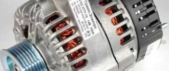
All generators are divided into alternating and direct current generators. Modern passenger vehicles are equipped with alternating current generators with a built-in diode bridge (rectifier). The latter is necessary to convert current into direct current, on which the vehicle's electrical consumers operate. The rectifier, as a rule, is located in the cover or housing of the generator and is integral with the latter.
All electrical appliances of the car are designed for a strictly defined operating voltage range. As a rule, operating voltages are in the range of 13.8–14.7 V. Due to the fact that the generator is “tied” with a belt to the engine crankshaft, it will work differently . It is for smoothing and regulating the output current that the relay-voltage regulator is designed, playing the role of a stabilizer and preventing both surges and dips in the operating voltage. Modern generators are equipped with built-in integrated voltage regulators, colloquially referred to as “chocolate” or “tablet”.
It is already clear that any generator is a rather complex unit, extremely important for any car.
Basic information about the excitation effect
ATTENTION! A completely simple way to reduce fuel consumption has been found! Don't believe me? An auto mechanic with 15 years of experience also didn’t believe it until he tried it. And now he saves 35,000 rubles a year on gasoline! Read more". As is known, the voltage generated by the gene at different engine speeds is regulated by excitation windings
The current is maintained at a constant voltage – 13.8-14.2 V
As is known, the voltage generated by the gene at different engine speeds is regulated by excitation windings. The current is maintained at a constant voltage - 13.8-14.2 V.
To provide the automotive system (numerous consumers) with current, a regulator or LV is provided. It can be found on domestic cars and some foreign cars; as a rule, it is built inside the generator. In everyday life, such a regulator is called a chocolate bar, a tablet, etc.
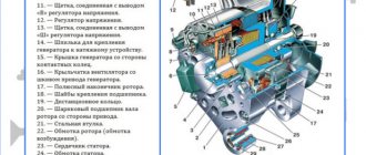
The gene is connected to the positive terminal of the battery through terminal “30”. It is also called plus, "B" or "BAT". As for the negative output, it is designated as “31” or minus. Also in everyday life there are other designations: “D”, “B-”, etc. The tablet terminal used to supply power from the vehicle network when the ignition is on - terminal “15” or “S”. Finally, the terminal designed to supply current to the charging test lamp is designated “61” or “D+”.
Voltage regulator or chocolate bar
If the battery stops charging, this in most cases indicates damage to the chocolate bar. However, you shouldn’t despair here, because it will be enough to apply voltage to the windings, that is, to excite the generator in order to get to the store or the nearest service station.
So, in order to get to the right place without subjecting the battery to a deep discharge, you need to remove the chocolate bar and excite the gene.
Types of generator faults
Due to the fact that any generator is an electromechanical device, there will be two types of faults - mechanical and electrical.
The first includes the destruction of fasteners, housing, malfunction of bearings, pressure springs, belt drive and other failures not related to the electrical part.
Electrical faults include winding breaks, diode bridge faults, brush burnout/wear, turn-to-turn short circuits, breakdowns, rotor beating, and relay-regulator faults.
Often, symptoms that indicate characteristics of a faulty generator can also appear as a result of completely different problems. As an example, poor contact in the fuse socket of the generator field winding circuit will indicate a generator malfunction. The same suspicion may arise due to burnt contacts in the ignition switch housing. Also, the constant lighting of the generator malfunction indicator lamp can be caused by a breakdown of the relay; the blinking of this switching lamp may indicate a generator malfunction.
The main signs of a faulty generator:
- When the engine is running, the battery discharge warning lamp flashes (or stays on continuously).
- Discharging or overcharging (boiling) of the battery.
- Dim car headlights, a rattling or quiet beep when the engine is running.
- Significant change in headlight brightness with increasing speed. This may be acceptable when increasing the speed (re-throttle) from idle, but the headlights, having lit up brightly, should not increase their brightness any further, remaining at the same intensity.
- Extraneous sounds (howling, squeaking) coming from the generator.
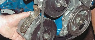
It is necessary to regularly monitor the tension and general condition of the drive belt. In case of cracks and delaminations, immediate replacement is necessary.
How to test a generator with a multimeter
The diode bridge of the generator can be checked with a multimeter, but you can also use the stand that was used to check the regulator.
But before that, first of all, without removing the rectifier bridge from the generator, connect the red wire of the tester to terminal 30 of the generator, and the black wire to the housing. Set the tester operating mode to dial (diode icon). If it is not there, then set it to 1-2 kOhm. The multimeter should show infinity. If the readings are different, the diode bridge is faulty.
Then check the current rectifiers for breakdown. Leave the positive (red) probe on terminal 30, touch the negative one to the bridge mounting bolts one by one. The multimeter display should show infinity in all cases; any others mean a breakdown.
Next, connect the positive probe to the axle mounting bolts, and the negative probe to the generator housing. In this case, the tester should also output infinity.
But in practice, such verification is most often not enough. In most cases, it is necessary to ring the generator in more detail.
Careful testing
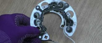
To do this, unscrew the fastening bolts of the rectifier unit, disconnect the copper wires of the stator winding and remove the diode bridge from the generator.
Now you can test each semiconductor individually. Before checking, it is advisable to rinse the stabilizer with running water using a medium-hard brush, and then dry thoroughly. For quick drying, a hair dryer is quite suitable. Attach one of the tester probes to the diode plate, connect the second to the central terminal of each diode fixed to this plate. Then swap the probes. In one case, the multimeter should show infinity, in the other - a nominal resistance of approximately 570-590 Ohms. Rectifiers are considered faulty if:
- In the first and second measurements (when the polarity was changed), the multimeter readings are the same;
- Diode resistance is greater or less than nominal values.
Perform the same actions with the second plate of the diode bridge. If a fault is detected in one or more diodes, it will be easier to replace the entire rectifier unit. True, there are craftsmen who replace failed diodes individually, but such work requires a certain skill and dexterity.
Checking the armature and stator windings
Further inspection requires completely disassembling the generator.
First of all, visually check the anchor. Brush rings should not show any blackening, chipping or wear on the treadmills. Blackening and slight wear can be smoothed out with zero-grade emery cloth. Rings with deep grooves must be replaced or, if the thickness of the rings allows, turned on a lathe. The armature winding should not clearly smell like burning . The color of the winding must be uniform and free of damage and breaks. To check the armature winding for a break, you will need a multimeter. Set the operating mode to continuity testing or resistance measurement and connect the probes to the brush rings. The winding resistance should be within 3-5 Ohms. Then leave one probe on the ring, connect the other to the body. The multimeter display should show infinity.
The generator stator is diagnosed after removal from the housing. First of all, carry out a visual inspection. There should be no visible damage to the wire or its insulation. Then connect the tester wire to the stator housing. With the second wire, touch the terminals one by one. There are only three of them. The tester must be in dialing mode. If the display shows infinity, this indicates that the stator is working properly.
Further testing consists of diagnosing the windings. The resistance of all three windings must be the same.
Before assembling the generator, you need to check and, if necessary, replace the bearings. When turning, they should not jam or make a creaking sound. This means that they are very worn out and will soon fail. Therefore, it is better to replace them immediately .
Generator repair kits
To eliminate these generator malfunctions, you will need to carry out repairs. When you start searching for a generator repair kit on the Internet, you should prepare for disappointment - the kits offered usually contain washers, bolts and nuts. And sometimes the generator can only be restored to functionality by replacing brushes, a diode bridge, a regulator... Therefore, the brave person who decides to repair it makes an individual repair kit from those parts that fit his generator. It looks something like this, as shown in the table below, using the example of a pair of generators for a VAZ 2110 and a Ford Focus 2.
| Generator KZATE 9402.3701-03 | ||
| Detail | Catalog number | Price, rub.) |
| Brushes | 1127014022 | 105 |
| Voltage regulator | 844.3702 | 580 |
| Diode bridge | BVO4-105-01 | 500 |
| Bearings | 6303 and 6203 | 345 |
What else could it be?
Often, the culprit for charging problems may not be the regulator itself, but its terminals; over time, like many on a car, they oxidize - which prevents the generator from working normally and recharging our battery, so first, before changing this unit, try to clean it, remove oxides and other deposits. By the way, this also applies to the battery terminals; they need to be cleaned and protected at least once a season.
Therefore, first of all, if the multimeter gives you 11 or slightly below 12V at the terminals of the machine, try cleaning the terminals and contacts first, then measure again. It is quite possible that this is the reason.
This is where I end the article, I think it was useful, read our AUTOBLOG.
(
31 votes, average: 4.32 out of 5)
Similar news
Spark plug gap. What should it be and what does it affect?
DIY brake caliper repair. Plus detailed video
Is there an automatic clutch? Let's look at the technical components.
Troubleshooting
On modern cars, using the “old-fashioned” diagnostic method by removing it from the battery terminal can lead to serious damage to many of the car’s electronic systems. Significant voltage drops in the vehicle's on-board network can damage almost all on-board electronics. That is why modern generators are always checked only by measuring the voltage in the network or diagnosing the removed unit itself on a special stand. First, the voltage at the battery terminals is measured, the engine is started, and readings are taken while the engine is running. Before starting, the voltage should be about 12 V, after starting - from 13.8 to 14.7 V. A deviation towards the higher side indicates that you are “overcharging”, which implies a malfunction of the relay regulator, towards a lower level - that no current is flowing. The absence of recharging current indicates a malfunction of the generator or circuits.
How to test the generator regulator relay. Do it yourself, using a multimeter. Very simple
Problems of “undercharging”, as well as “overcharging” of the battery in principle, can be caused by many reasons, but the very first and most common on many cars (our VAZs are no exception here), as well as on many motorcycles, is the output of the generator relay-regulator from building. This device, despite its compactness, will protect your battery and make its service life much longer. However, if they fail, it can simply kill the battery in a matter of weeks, so if you see white streaks, and also, the engine does not start after night, even the starter does not “turn” - it’s time to check the relay regulator of your car, and here’s how it works do it yourself, and today I’ll tell you in detail...
THE CONTENT OF THE ARTICLE
To begin with, the definition
A relay regulator is a device that regulates the current from the car's generator, preventing the battery from overcharging, protecting it from overcharging, which is detrimental to the battery. Thus, this device greatly extends the battery life.
Essentially, this is just a voltage stabilizer that prevents the voltage from the generator from exceeding the threshold of 14.5 Volts; it is a very accurate device and is required for all types of cars. However, it can be distinguished into two types.
Causes of breakdowns
Common causes of generator malfunctions are simple wear and corrosion. Almost all mechanical failures, be it worn brushes or collapsed bearings, are a consequence of long-term use. Modern generators are equipped with sealed (non-maintenance) bearings, which simply must be replaced after a certain period or mileage of the vehicle. The same applies to the electrical part - often the entire components must be replaced.
Also reasons may be:
- low quality components;
- violation of operating rules or operation outside normal operating conditions;
- external factors (salt, liquids, high temperature, road chemicals, dirt).
Types of Voltage Regulators
Having understood what types of these devices there are, what their features and properties are, a complete understanding of the procedures carried out during testing will come. This will also give the answer to what scheme, in what way and how to check the generator voltage regulator. There are two types of regulators:
In the first case, it is meant that the regulator housing is combined with the brush assembly directly in the generator housing. In the second case, the regulator is a separate unit, which is located on the car body, in the engine compartment, and wires from the generator go to it, and wires from it go to the battery.
A special feature of the regulators is that their housings are non-separable. They are usually filled with sealant or special resin. And there is no particular point in repairing them, since the device is inexpensive. Therefore, the main problem in this regard is to check the generator voltage regulator relay. Regardless of the type of regulator, the voltage symptoms will be the same.
Self-test of the generator
The easiest way is to check the fuse. If it is in good condition, the generator and its location are inspected. The free rotation of the rotor, the integrity of the belt, wires, and housing are checked. If nothing arouses suspicion, the brushes and slip rings are checked. During operation, the brushes inevitably wear out, they can become jammed, skewed, and the grooves of the slip rings become clogged with graphite dust. A clear sign of this is excessive sparking.
There are frequent cases of complete wear or failure of both bearings and stator failure.
The most common mechanical problem with a generator is bearing wear. A sign of this malfunction is a howling or whistling sound when the unit is operating. Of course, the bearings must be replaced immediately, after first inspecting the seats. Loose drive belt tension can also cause poor generator performance. One of the signs may be a high-pitched whistle from under the hood when the car accelerates or accelerates.
To check the rotor field winding for short-circuited turns or breaks, you need to connect a multimeter, switched to resistance measurement mode, to both contact rings of the generator. Normal resistance is from 1.8 to 5 ohms. The readings below indicate the presence of a short circuit in the turns; above – direct winding break.
To check the stator windings for ground fault, they need to be disconnected from the rectifier unit. If the resistance readings given by the multimeter are infinitely large, there is no doubt that there is no contact between the stator windings and the housing (“ground”).
To check the diodes in the rectifier block, use a multimeter (after completely disconnecting it from the stator windings). The test mode is “diode test”. The positive probe is connected to the plus or minus of the rectifier, and the negative probe is connected to the phase terminal. After this, the probes are swapped. If the values of the multimeter readings differ greatly from the previous ones, the diode is working; if they do not differ, it is faulty. Another sign indicating the imminent “death” of the generator diode bridge is oxidation of the contacts, and the reason for this is overheating of the radiator.
How to excite a gene
So, what needs to be done to excite the generator? As mentioned above, the tablet should be removed from the generator, since the malfunction arose precisely there. Next, connect the positive terminals of both devices, and cut the negative terminal in the chocolate bar. During the assembly process, connect it to a mass of brushes.
Insulate the wire from terminal “30” of the gene, connect an indicator with a power of no more than 15 W to the output circuit “15”. This applies to the genes of the G222 series. If the units are of other models, then they must be excited by connecting the indicator to terminal “B”.
Self-excitation of a generator can be imagined this way.
Scheme 6
In the diagram above, the leftmost arrows indicate diodes. They are installed only in generators of modern models; they do not exist in older units. More precisely, the circuit without the presented diodes is considered classic, and with them - modernized, modern.
In some gene models, the anchors imply the presence of brushes. They are also removed and the tablet is drilled out. One contact goes directly to the armature through the diodes to the plus, as can be seen in the diagram, the second contact goes to the minus (lowest arrow).
Accordingly, the diagram shows: plus and minus.
The current will not begin to flow immediately, that is, not at low speeds. Somewhere, if you look at the tachometer, voltage will begin to be generated after 4000 rpm. In other words, we rev up to 4 thousand rpm and current appears. If we go down to 1 thousand rpm or less, the voltage disappears and we will need to rev the throttle again. This is approximately the principle of current generation during self-excitation.
Some cars have a low-speed engine. In this case, you will have to do something with the pulleys to increase the initial rotation speed. For a normal engine everything should be fine.
Excitation system in the generator
Go ahead. The output is not 12 volts, you should know this from the beginning. Without a regulator, the gene will output whatever it can, up to 20-30 volts. For example, during start it reaches 36 volts. This can be checked by using a light bulb of this voltage connected to the outputs. Then it drops to 20 volts.
The scheme can certainly be improved. For example, embed a capacitor into the positive wire going to the armature. This is done in order to prevent a drop in voltage when the engine speed drops. A good capacitor can also be placed at the output to smooth out the first voltage surge and regulate and smooth out dips.
When implementing this circuit, it is important to remember about delivering high voltage. This is not 12 volts, you can easily burn out light bulbs, the ECU and basically all car electrics
Warning. In self-excitation mode, the gene will give everything it can without any restrictions, which is fraught with overheating for itself. A little more load, and write a eulogy to the generating device. Therefore, this method is applicable only as a necessary measure, again, if you are left on the road and need to get to the nearest service station.
Repair and troubleshooting
All mechanical problems are eliminated by replacing faulty components and parts (brushes, belt, bearings, etc.) with new or serviceable ones. Older generator models often require grinding of slip rings. Drive belts are replaced due to wear, maximum stretching or expiration of service life. Damaged rotor or stator windings are currently being replaced with new assembled ones. Although rewinding is common among auto repair services, it is becoming less and less common - it is expensive and impractical.
But all electrical problems with the generator need to be solved by checking both other elements of the circuit (in particular the battery), and directly its parts and output voltage. One of the common problems that car owners have to deal with is overcharging , or, conversely, low voltage of the generator . Checking and replacing the voltage regulator or diode bridge will help eliminate the first malfunction, but low voltage output will be a little more difficult to deal with. There may be several reasons why the generator produces low voltage:
- increased load on the on-board network by consumers;
- breakdown of one of the diodes on the diode bridge;
- failure of the voltage regulator;
- slipping of the poly V-belt (due to low tension)
- poor contact of the ground wire on the generator;
- short circuit;
- drained battery.
Without a properly charged battery, the machine cannot be operated. If you notice that there is no charging on your VAZ 2107, the problem must be repaired immediately. If you continue to use the car, especially at night, the battery will run out very quickly and you will have to use a tow truck or tow truck. To figure out why the battery is not charging and how to fix the problem, you need to start with theory.
Checking the combined relay-regulator of the car
First we will check the combined relay-regulator circuit together with the brush assembly. These are now installed on many foreign cars, and by the way, on many domestic cars (often labeled Y212A).
As you understand, it is necessary to remove the generator and disassemble it, since this combined unit is attached at the back next to the generator shaft, along which these brushes run. For this:
- We look for a special “window” on the back of the generator where the brushes are immersed.
- Unscrew the fastening bolt.
- Remove the brush assembly.
- We clean it - as a rule, it will be covered in graphite dust; the brushes are made of graphite, using special carbon.
Then we need to check it, but for this we assemble a certain circuit, it is advisable to use a power supply with an adjustable load or a charger. We also need to take a regular 12V light bulb from a car, for example from a “dimensions”, we will need wires to assemble the entire system.
We may need a battery, because many chargers do not work without it. But from the wire from the battery we connect the relay-regulator, to the brushes of which we connect a 12V light bulb, this can be done with small alligator clips, the main thing is not to break the graphite elements. A small diagram for understanding.
If you connect everything in a calm state, the light will simply light up and stay lit, this is normal, since the brush assembly is a conductor of electricity from the shaft. Let me remind you that in a calm state, the voltage on the brushes will be approximately 12.7V.
Now we need to raise the voltage on the charger to 14.5 V, the lamp will light, but when this threshold is reached it should go out! That is, 14.5 V is a kind of “cutoff” for a further increase in voltage! If you lower the value, the lamp should light up again. Then your relay-regulator is working, it passed the test.
VAZ 2107 generator and reasons for lack of charging
To start the engine and proper operation of the ignition system and other electrical circuits of the VAZ 2107, it is necessary to have DC voltage in the on-board network. When the engine is not started, the battery maintains the proper voltage. After the engine starts, the car's generator charges the battery and maintains the on-board voltage at 13.6-14.2 V. Regardless of engine speed, the output voltage at the generator remains constant. A relay-regulator is responsible for this, which changes the voltage of the generator excitation circuit. If the voltage rises above the permissible level, the winding current decreases, reducing the output voltage. And vice versa.
A little theory
During operation, a dead battery is charged with a constant voltage of 13.6-14.2 V in the vehicle's on-board network. For proper operation of the car and its systems, this voltage is maintained by the battery itself until the generator rotor begins to rotate at a frequency of 800-900 rpm. Then it produces electricity sufficient for normal operation of the car and charging the battery. Under different engine operating modes, when the engine crankshaft speed changes, the generator rotor speed also changes, which leads to an increase in the voltage at the generator output. To maintain a voltage of 13.6-14.2 V in the on-board network, a voltage relay-regulator (RR) is included in the generator excitation circuit, which, when the network voltage increases above the rated voltage, reduces the current going to the generator excitation winding. The magnetization of the rotor poles decreases, which leads to a decrease in its output voltage.
The reasons that the generator does not charge the battery are related to the elements of the excitation circuit or the output voltage circuit from the generator to the battery, including parts of the generator.
When the ignition is turned on, the lock also turns on the ignition relay. In this case, +12 V passes through the relay contacts and fuse No. 10 of the mounting block, then is supplied to the on-board network and to the output of the battery charge indicator lamp and the charging sensor. Then they go through the diode, the mounting block (plugs Ш5-Ш10), and are fed to plug “61” of the generator 37.3701, which have been installed on the VAZ 2107 since 1988. Next, +12 V goes to the terminal of the built-in PP and through the brush and slip ring to the winding excitation - the starting excitation of the generator is performed. As the engine speed increases, and with it the generator rotor, the phase voltage increases, and through a block of additional diodes it increases the voltage on the excitation winding and on the output diode of the battery charging indicator light. When the output phase voltage reaches +12 V at both terminals of the battery lamp, the voltage is equalized, and due to the absence of a voltage difference, it goes out. In this case, the VAZ 2107 generator produces a voltage of more than 12 V, which charges the battery.
The electrical circuit diagram of the VAZ 2107 car injector differs from the circuit diagram of the VAZ 2107 carburetor only in the presence of a piece of equipment that controls the power system, and does not affect the battery charge. Quite the contrary - malfunctions in the battery charging system can affect the operation of the injection engine ECU.
Powerful electricity consumers are controlled using electromagnetic relays connected to the network. Let's look at ways to troubleshoot battery charging problems for both injection and carburetor engines.
How to determine if the VAZ 2107 battery is not charging
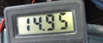
The first sign of a lack of charging is a burning indicator lamp on the instrument panel or a voltmeter needle that is not in the green sector when the engine is running. A more reliable way is to check the voltage on the battery using the will class=”aligncenter” width=”600″ height=”450″[/img]
When the engine is running, the normal voltage on the battery is 13.9±0.3 V. When the battery is not charging, the voltage on it is approximately 12 V.
Important: to avoid failure of the regulator relay and the electronic engine control unit, it is prohibited to remove the battery terminals while checking the on-board voltage while the engine is running.
Low and high voltage of the on-board network harms the battery. In the first case, it is discharged, in the second, the electrolyte boils away, which leads to battery failure.
What is needed to repair VAZ 2107 battery charging
To identify and troubleshoot problems, the following devices and tools are needed:
- multimeter;
- control lamp 12 V;
- flat screwdriver;
- knife;
- pliers;
- sandpaper.
How the charging system works
The battery in any car, in particular in the VAZ 2107, is only necessary for the functioning of the power supply system while the engine is turned off. But when the engine is running, all electrical equipment runs from the generator. It provides power to the injector - nozzles, fuel pump, electronic control unit. But the main load is the battery. It charges while the engine is running.
And the service life of the battery directly depends on how well the charging occurs. A generator is just one source of electricity. But it may be in working condition, but charging is not going to the battery. There can be a lot of reasons for this behavior; you need to thoroughly study the electrical circuit of the charging circuit of the VAZ 2107 car.
Troubleshooting VAZ 2107 battery charging problem
First, you should check the serviceability of the alternator belt - it is this that causes the alternator to rotate and generate current. This belt drives the coolant pump, so this malfunction also manifests itself in engine overheating.
If the charge indicator lamp does not light up, and the voltmeter shows normal voltage of the on-board network, and the battery does not charge, the reason is in the contacts at the terminals.
You should remove the wires from the battery and clean the battery terminals and wires with emery cloth. If the charge does not appear, it is necessary to measure the voltage at terminal “30” (generator output) with the engine running. If the voltage at this terminal and the battery is very different, you need to clean the contacts and ring the wire going from the generator to the battery. The faulty wire must be replaced.
If, when the engine is running, the voltage in the on-board network is within normal limits, but when a load (headlights) is connected, it drops, the reason lies in the weak tension of the alternator belt. As the load increases, the weakened belt slips. A correctly tensioned belt should bend by 12-17 mm with a force of 10 kgf. A loose belt must be tightened or replaced.
Important: if the belt is over-tensioned, excessive load occurs on the bearings of the generator and pump, which can lead to their failure.
Other reasons for the lack of charge may be a broken rectifier diode on the generator, an open or shorted rotor or stator winding.
Diodes can be checked using a multimeter or a test lamp. Using a multimeter, you can check the resistance of the diodes in the direction in which they should be locked. To check with a test lamp, you must remove the “+” terminals from the battery and connect the test lamp. The wire of the test lamp must be touched in succession to the three bolts of the rectifier devices. Then perform the same operation, only disconnecting the “-” terminal. If the lamp lights up, the diode being tested is broken.
If one of the diodes malfunctions, the diode rectifier assembly must be replaced.
A break in the stator winding is determined with a multimeter by measuring the resistance between the rectifier unit mounting bolts. Lack of contact between the winding and the other indicates its breakage. In this case, it is necessary to replace the winding or generator assembly.
A common cause of generator failure is brush wear. To check them, you need to dismantle the brush assembly. The length of the brushes must be more than 5 mm, otherwise they need to be replaced. Also, the brushes may become warped or “stick” in the wells. Therefore, it is necessary to check the condition of their side surface.
Note: the VAZ 2107 generator (carburetor) is no different from the unit for the injection version of the “Seven”. Therefore, all tips for checking and repairing the generator are relevant for both modifications of the car.
If the warning lamp does not light up and other devices do not work when the engine is running, and the battery is not charging, the reason is a blown fuse or a breakdown of the ignition switch (relay).
The reason for the lack of battery charging may be a breakdown of the relay regulator. To check it, you need to connect “+” from the battery to the top contact, and “-” to the left one and check the voltage on the brushes, which should be 12 V. If the voltage is lower, the relay regulator must be replaced.
There are two energy sources in a car. Battery and generator. Moreover, the generator is the main one, since it is able to charge the battery while driving. In the most extreme, desperate cases, battery energy can be used. According to various estimates, in the most optimistic case, you can drive about 100 km on a flat road on a battery. In this case, the headlights should not be turned on, the heater should not be turned off, and, preferably, the ambient temperature should be low and the speed should be constant so that the radiator fan does not turn on. And the battery will be fully charged. Only in this case all the energy will go into the “spark”.
If the VAZ 2107 engine (injector) is running and there is no battery charge, there may be many reasons.
Types of relay-regulator
To exaggerate, there are only two types, but each works on the same principle, namely, “cuts” or increases the voltage to the desired level.
- Combined with brush assembly. Usually it is mounted on the generator itself, in the housing where the brushes are located, there is also a relay regulator.
- Separate. Usually it is mounted on the car body, the wires go from the generator to it, and only then to the battery.
The housings are non-separable and tight and of a different type (often filled with sealants or special adhesives), that is, they cannot be repaired. To be honest, they are quite cheap, especially for our VAZs, so it’s easier to buy a new one than to tinker with an old one.
These are the most common types, of course, previously there were so-called ones combined with terminals, but they didn’t catch on because the device is not very convenient, so I won’t talk about them.
If your relay is “broken” and is constantly recharging, then it’s worth changing it, but first you need to make sure that this is the problem. Now there are only two ways to check: - without removing it on the car itself, and checking an already removed relay. Let's look at both options.
What reasons can cause the charging relay to fail?
Only two, not counting severe damage to the generator housing:
- “planned” wear of brushes, which are graphite electrodes. In this case, the contact is gradually broken and disappears completely. As a result, no current is supplied to the excitation winding of the generator, and it does not work;
- A short circuit has occurred in the electrical circuit itself, while there is an output current on the generator and battery, but it is higher than 14.8 V.
The charging relay is located on the generator, on its back cover, and, no matter what shape and color the “tablet” is, a yellow wire comes out of the generator body to it. The relay is located so that it can be replaced without removing the generator. But for convenience, the pictures show work on a removed generator.
Powering the rotor with direct current: process features
In order for the magnetic field in the rotor not to change direction, its coil must be powered by a direct current of the same polarity. Current is supplied to the rotating coil through carbon brushes and commutator rings.
To power the rotor winding with direct current, two methods are used: self-excitation and excitation from an external source (usually from a battery).
Rice. 3.14. Toothed generator rotor.
Generator Excitation: Understanding the Definition
Excitation of the generator is a process that occurs on the basis of magnetomotive force. It carries out the process of inducing a magnetic field, which, in turn, produces the process of generating electricity. To excite the first generation generators, special DC rotators were used, which are also called exciters. Their winding received DC power from another generator, which is usually called a sub-exciter. All components are placed on one shaft, and their rotation occurs synchronously.
Generator field winding: familiarization with the definition
The generator excitation winding is one of the main structural elements of a synchronous generator. It receives power from a source providing direct current. Most often, the source function is performed by an electronic voltage generator. Such regulators are used in new models operating on the basis of a self-exciter. And self-excitation, in turn, is based on the fact that the initial excitation occurs with the help of the residual magnetism of the magnetic circuit of a synchronous generator (SG). It is important to understand that alternating current energy comes precisely from the SG stator winding, transforming it into direct current energy.
What is the generator excitation winding used for?
The rotor winding is excited by a direct current source. The rotor rotates with the help of the prime mover, thereby the magnetic field created in the rotor also rotates with it at the same speed. Now the magnetic field lines cross the stator winding located around the rotor. As a result, an alternating electromotive force (emf) is formed in the winding.
How to replace the charging relay?
- Important! First, as always, we turn off the ground, remove the negative wire from the battery terminal, then remove the yellow wire going from the generator to the relay, then use a Phillips screwdriver to unscrew it;
- Then we take it out together with the brushes:
- Now we need to carry out diagnostics. To do this, we test the voltage on the brushes with a voltmeter, and we power the relay itself from the battery, “simulating” the rectified current of the generator. At the same time, we apply (+) to terminal “B”, to the yellow wire, and connect (-) to the other terminal, “ground”. We are familiar with the signs of trouble. If you don’t have a tester, you can take a 1-3 W, 12 V light bulb.
- When installing a new relay, you need to press it firmly during installation, since new, unworn brushes provide more resistance.
If after taking these measures there is no effect, you need to look for the cause in the generator, we’ll talk about this next time. At the same time, remember that if you are removing a generator, then either you have decent knowledge in electrical engineering, or you have someone to give it to. There is no third option, especially if you have an injector.
In conclusion, let me tell you about several other reasons for the lack of charging or imitation, and also give advice:
- If you have a VAZ 2107 injector, then it is strictly not recommended to reset the battery terminal for various “checks” while the engine is running, and especially to allow strangers near the hood for this purpose. This is very harmful to electronic “brains”.
- It is advisable for those who like to “light up” to be able to say a firm “no” if you have a VAZ 2107 injector.
- On the instrument panel, the connectors are not soldered to the board, but riveted. Therefore, in some cars in the cold, while the interior is cold, there is no contact with the charging lamp. It lights up, simulating a lack of current from the generator. After the interior has warmed up, contact is restored and the lamp goes out.
- The next reason for those who like to go to the car wash in the cold. When water gets into the relay and brush assembly and freezes there, there is no charging. The solution is to heat it with any powerful hairdryer.
FakeHeader
Comments 16
My brain explodes at the end of the article! Maybe I didn’t understand correctly, but from what I read I concluded that from the generator, namely, from the brushes, we throw the wire to the relay on pin 67, and from pin 15 we throw the wire again on the generator, namely on the M8 threaded stud, where 2 thick wires. So? Did I understand everything correctly?
So, here it would be necessary to be more precise. if you have a wire from the brushes going to the diode bridge, then you need 67 from the brushes and 15 to the wire that was inserted into the brushes. if not, then the wire comes from the brushes at 67 and 15 goes to that pin. But in this and in the case that the wire is a pin, this is the + output.
In general, I have an Oda and it has a VAZ2105 type generator with a tablet in the generator on the brushes, I bought myself a generator from a VAZ 2101 and now I’m looking for information on how to connect it. I have only 2 wires coming from my original generator, one double, on the M8 stud, the other to the terminal on the generator, and now a terminal has formed from the brushes, that’s the question, that’s why I’m asking how to properly connect with an external relay. I myself am not an electrician, for me these are murky miracles))) That is, as I understand it, we loop the relay on the generator from brushes 67 and from 15 to the M8 pin, leaving everything else unchanged? I looked at the diagram in the article, where the wire from the gene goes to 67 in the relay, and from 15 to the fuse block, here I am in a stupor... firstly, where to connect in the block, and secondly, the option with a loop confused me, because . It turns out 2 different connection options.