05 November 2015 Lada.Online 260 166 11
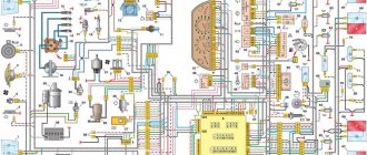
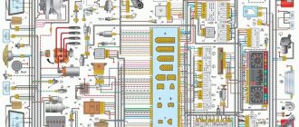
During the operation of the car, problems may arise that can only be solved after studying the electrical circuits. The article presents detailed wiring diagrams for the Lada 4×4 SUV (VAZ 2121), which will help you not only repair the car, but will also be useful when installing additional electrical equipment, for example, a car alarm, DVR and other accessories..
Circuit breakers
F1 (5A)
- License plate lamps
- Instrument lighting lamps
- External lighting indicator lamp in the instrument cluster
- Engine compartment lamp
- Additional brake signal lamp
- Left side marker lamps
F2 (7.5A)
- Low beam lamp (left headlight)
- Electric headlight corrector
- Corrector motor gearbox
F3 (7.5A)
- High beam lamp (left headlight)
- Indicator lamp for high beam headlights
F4 (10A)
Left fog lamp
F5 (30A)
- Power window relay
- Electric windows
F6 (15A)
- Before 2009:
Door lock control unit - After 2009:
Cigarette lighter
F7 (20A)
- Before 2009: Cigarette lighter
- Horn relay
- Sound signal
- Horn relay
F8
- Before 2009 (20A): Heated rear window relay (contacts)
- Rear window heating element
- Heated rear window relay
F9 (20A)
- Before 2009: Glove compartment lamp
- Windshield wiper relay
- Windshield wiper switch
- Windshield wiper motor
- Headlight wiper relay (contacts)
- Electric motors for headlight wipers
- Headlight washer motor
- Heated tailgate glass switch
F10 (20A)
- Before 2009:
Reserve - After 2009:
Electrical accessories remote control unit (door lock)
F11 (5A)
- Tail lamps
- Instrument lighting control
F12 (7.5A)
- Low beam lamp (right headlight)
- Corrector motor gearbox (right headlight)
F13 (10A)
High beam lamp (right headlight)
F14 (10A)
Right fog lamp
F15 (20A)
- Exterior mirror control unit
- Electric drives for exterior rear view mirrors
- Exterior mirror control unit
F16 (10A)
Relay-breaker for direction indicators and hazard warning lights (in hazard warning mode)
F17 (7.5A)
- Individual lighting lamp
- Immobilizer warning lamp
- Brake light bulbs
- Additional brake signal
- Interior lighting
F18 (25A)
- Before 2009: Reversing lamps
- Electric heater fan
- Windshield washer motor
- Heated rear window relay (coil)
- Rear window wiper relay
- Rear window wiper motor
- Rear window washer motor
- Door lock control unit
- Heater motor switch
F19 (10A)
- Before 2009: Relay interrupter for direction indicators and hazard warning lights (in turn signal mode)
- Instrument cluster (except engine management system malfunction warning lamp)
- Differential lock indicator lamp
- Starter relay
F20 (7.5A)
- Before 2009:
Rear fog lights - After 2009:
- Rear fog lights
Anti-theft system control unit (Since 2009)
Buzzer (Since 2009)
- Fog lamps in the rear lights
- Anti-theft system control unit (Since 2009)
- Buzzer (Since 2009)
K1
- Until 2009:
Relay for monitoring lamp health (jumpers are installed instead of relays) - After 2009:
Windshield wiper relay
K2
- Before 2009:
Windshield wiper relay - After 2009:
Relay-breaker for direction indicators and hazard warning lights
K3
- Before 2009:
Relay interrupter for direction indicators and hazard warning lights - After 2009:
Low beam relay
K4
- Before 2009:
Low beam relay - After 2009:
High beam relay
K5
- Before 2009:
High beam relay - After 2009:
Auxiliary Relay (Tailgate Defogger Relay Coil, Heater Fan, Windshield Wiper and Washer, Tailgate Wiper and Washer)
K6
- Before 2009:
Additional relay (Relieves ignition switch contacts) - After 2009:
Heated tailgate glass relay
K7
Heated tailgate glass relay
Video “Laying wiring in the sports version of the Niva”
You can learn more about this process from the video (author - Suprotec Racing channel).
Scheme of the first VAZ-2121
Years of manufacture: 1977-1993 content-27.foto.my.mail.r…ail/mr.chvans/79/s-94.jpg With tail lights and instruments from 2106
Scheme VAZ-21213 (Carburetor)
Years of manufacture: 1993-2009 content-25.foto.my.mail.r…ail/mr.chvans/79/s-97.jpg The diagram shows a relay for rear fog lights, used since 2000, before that they were turned on directly from the latching switch.
Since 2004, the car was renamed from NIVA to LADA 4x4
Since 2013, daytime running lights began to be used: a 2-filament lamp is installed at the side lights in the side light section. When the ignition is turned on, the power comes to the 21W thread (running lights mode), when the external lighting is turned on, the power switches to the 5W thread (side lights mode).
Schemes of the carburetor mixture control system are here www.drive2.ru/b/2168677/ There is a little information about the devices at the end of this article www.drive2.ru/b/1087776/
No more information available. I'll add what I find out. If you have anything to add or correct, write in the comments.
Designations of fuses and their purpose
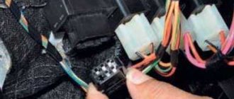
To protect electrical circuits on cars, fuses are used, located in a special mounting block. On a Chevrolet Niva VAZ 2123, this block is located inside the instrument panel, to the left of the plastic steering column cover.
The placement of blocks in the cabin is the same for cars of all years of manufacture.
The main blocks of machines are divided into two types - before 2009 and after. These devices are not interchangeable. The blocks behind the glove box are identical in design.
On a 2005 car, you can easily install a block from a 2011 car. The designation of the fuse rating is marked on the body; on the assembly itself there is a number of the fuse link and a pictogram of the purpose.
There are no fuse markings on the main unit cover.
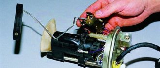
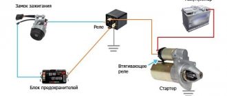
A typical fuel pump relay 75.3777-10 has 4 contacts, a coil with an armature, and a spring for opening the contact. When voltage is applied to the control contacts, the rod is drawn into the winding and another pair of contacts is closed. It turns off automatically as soon as the low-current connectors are de-energized.
Advantages of using relays in Niva Chevrolet cars:
- spontaneous leakage current in the on-board system is eliminated;
- reliable control of all electric motors;
- quick and guaranteed start of electrical mechanisms;
- Network overload protection.
Lada 4×4 3D 2121 › Logbook › Electric fans 21214 in 2121
Just a short note about the installation. Inspired by an article on Niva-Fak and tired of constant boiling, I broke my piggy bank and went to the local car market, where I purchased: 1. Electric valves 21214 2. Tee for a sensor from a GAZelle 3. Sensor TM-108 87-92 degrees 4. Relay 711.3747-01 5. Fuse 30A 6. VAZ-2101 heater control button 7. Rubber radiator pads from VAZ-2108 2 pcs. So, part one is installation. In the article at the link, the guy writes that he barely inserted the valves into the face, raised the steering wheel, tightened it, sawed it off and installed it - DON’T DO THIS!
The valves rest with their lower legs against the holes in the muzzle, and with the upper rubber bands they press the radius against the top of the muzzle, and that’s it. Nothing warps or rubs, everything works PERFECTLY. And the sides on the upper elastic bands hint to me personally that this is how it should be, there is no need to cram in what cannot be squeezed in. At the same time, they unscrewed the native Carlson so that it would not take away the power from the already shaky Pihl. Also in the process, the gene belt was replaced, because it was slightly worn. The threesome with the sensor was cut into the lower pipe, it didn’t go in without a curse, but it went in.
The photo is not so great, but the car looks clearly better
Part two - connection. The diagram in the article, unlike the instructions, is more clear. Everything was connected according to it, only the wires on the button were swapped: ground with any other.
Result: the scheme works, but they hum - mother, don’t worry. for some reason you immediately feel like you’re on a Junkers
The sensor turned out to be too hot - according to the display meter, it turns on when the needle has already crept well over 90. The voltage at 2000 rpm with the valves on drops to 13 volts
Features of electrical equipment
The standard wiring on the VAZ 21213 differed from the circuit used on the VAZ 2121. In particular:
- The fuse box on the VAZ 21213 uses more modern “knife” fuses, for which the contact pad is modified;
- The power system uses EPHH - forced idle economizer, for which there is a separate harness with a block in the engine compartment wiring;
- The ignition system uses a non-contact circuit built on a microcontroller.
Differences in the engine compartment
The EPHH control unit is located in the engine compartment and is a plastic box with a connector for connecting a wiring harness to it. Its purpose is to ensure stable engine operation when coasting, including fuel economy.
Self-diagnosis capability
To make it easier to determine engine failure, car owners use a search algorithm based on the car manufacturer’s recommendations.
The manufacturer recommends using it first, and only then resorting to the help of another car:
- Use of known good parts;
- Easy start (“lighting up”), etc.
Conclusions: self-service of a car has long become the norm for our car owners. Moreover, video manuals with explanations of the work have become more accessible today, allowing you to avoid mistakes when troubleshooting the electrical network.
Ignition system
The operation of the internal combustion engine installed on the VAZ 2121 car is based on a classic scheme, a video of which is shown in driving courses:
- The generator produces electric current;
- The ignition coil increases its power;
- The ignition distributor supplies electrical impulses to the spark plugs when the piston reaches TDC;
- The spark plugs ignite the air-fuel mixture in the engine cylinders.
The photo shows the following components:
- From pos. 3 to 12 – ignition coil and its structure;
- From pos. 13 to 20 – spark plug;
- From pos. 21 to 42 – ignition distributor (distributor).
For reference: The distributor slider, which is responsible for closing the contacts with the high-voltage wires going to the spark plugs of each cylinder, is shown separately. In the diagram presented, it is indicated by pos. 41-45.
Engine modernization
The all-wheel drive transmission of the VAZ 2121, in addition to significant advantages, also had domestic disadvantages. In particular:
- Fuel consumption was quite high compared to passenger cars (13.4 liters per 100 km in urban conditions and off-road);
- This was reflected in operating costs - the price of 1 km was much more expensive for the owners. And the power of the existing engine was insufficient for harsh off-road conditions.
For reference: the automaker, by modernizing the existing engine, increased its technical parameters. In particular, the volume increased from 1480 cubic meters. cm up to 1680 cc see Cars with such a power unit received the factory index VAZ 21214.
An increase in engine displacement and the use of a non-contact ignition system led to the need to modernize the electrical circuit in the engine compartment. Replacing the VAZ 2121 wiring solved this problem completely.
Ignition system modernization
Since the high-voltage coil is traditionally responsible for the sparking power, the automaker has made changes to its operation. In particular, the wiring on the VAZ 2121 was supplemented with a harness that connected the switch and other components of the ignition system.
This factory manual contains:
- Ignition switch acting as an electrical circuit switch with pins 30/1 and 15;
- Ignition relay with pins 85,86,30 and 87;
- Switch with 6-pin terminal block;
- Upgraded ignition coil with terminals “B” and “K”;
- Distributor (ignition distributor);
- Candles.
Electrical wiring of VAZ 21213: differences in the engine compartment and the possibility of self-diagnosis
Like any other domestic car, the VAZ 21213 is in most cases serviced by the hands of its owner. This is the specificity and even the mentality of our car enthusiasts, who, in addition to tools, also require a technical description of the main components and assemblies.
And the detailed wiring diagram of the Niva VAZ 21213 is just one of them, since in harsh operating conditions it is often necessary to restore the car in field conditions, because:
- VAZ 21213 is an off-road vehicle;
- Used by owners away from service stations and workshops;
- The life and safety of people (the owner and his family members) living far from large cities often depends on its technical condition.
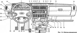
Dashboard
For subsequent modifications of the VAZ 2121, the instrument panel was thoroughly redesigned. In particular, the design and location of the warning lamps have changed, and new scales have appeared on the instrument panel indicators.
Conclusions: the owners of the VAZ 2121 car often serviced it themselves. And servicing electrical systems is impossible without original circuit diagrams. This was especially true for modernized versions, where changes were made to the operation scheme of components and assemblies.
Maintenance of wiring VAZ 21214 and other Niva models injector and carburetor: electrical diagram
Every modern car today is equipped with an electrical part. The electrical diagram of the VAZ 21214 Niva injector allows, if necessary, to find all the elements included in the on-board network, which is especially important when faults occur in the wiring. Everything a driver needs to know about electrics in domestic SUVs is described in this article.
Detailed electrical diagram of Niva
The wiring diagram may vary slightly depending on the design features of the vehicle.
First, let's look at the index notation:
- VAZ 21213. This index designates a vehicle equipped with a carburetor. The volume of the power unit is 1.7 liters.
- 21214. In VAZ 21214 cars, the scheme involves the use of a similar engine with the same volume. The only difference is that the car is equipped with a fuel injection system.
- There is another model with the index 21213. In VAZ 21213 cars, the electrical circuit includes the same elements, only depending on the year of manufacture, the car can be equipped with a 1.8 liter engine.
- Version 21073. The SUV is equipped with either an injection engine with nozzles or a Solex carburetor engine. One of the features of these cars is a contactless ignition circuit.
- 21215. These SUVs were originally produced for export, so these cars are difficult to find on our roads. It is worth noting that they were equipped with Citroen diesel engines.
At the beginning of the article there is a diagram of the VAZ electrical equipment using the example of the Niva 2121 model. If you are the owner of version 2131 or any other, then there will be a difference in the circuit diagram, but not fundamentally. If we are talking about carburetor engines, then in this case the battery charging circuit, as well as the ignition, will not be protected (video author - Nail Poroshin).
Features of electrical equipment
The electrical circuit of the VAZ model 21213 has certain differences with the model 2121, in particular:
- 21213 vehicles use more modernized foot fuses in the fuse box. Of course, the use of such devices led to the fact that the block site also became different.
- The power supply system of these vehicles additionally includes an idle speed saving device. For this option to work properly, another connector with wiring was added in the engine compartment.
- Another difference is that these cars use a non-contact ignition circuit, the main element of which is a microcontroller.
It should be noted that differences in the Niva circuit may lie both in the generator units and in the electrics themselves.
Differences in generators
In any case, the differences in the wiring diagram of the models will primarily depend on the power unit - carburetor or injection.
The main differences in carburetors:
- models 21213 use the generator unit model 371.3701;
- in the engines of models 21214, the manufacturer decided to install a more powerful generator device; it is marked with the numbers 9412.3701 (video author - Sergei Chekhonin).
And although these generators are different, they have certain similarities in design. In any case, it is a synchronous AC device. In addition, these units have a built-in rectifier and output voltage regulation mechanism.
Wiring differences
If we talk directly about wiring, then depending on the car model, it may also have differences. It should be noted that these differences greatly simplify do-it-yourself maintenance and repair of the system. As for injection modifications of SUVs specifically, in this case the system is equipped with three outputs intended for installing electronic ignition.
In addition, 21214 cars use two ventilating devices that perform the function of cooling the radiator assembly. Accordingly, due to the use of additional fans, the wiring also underwent, albeit not significant, differences. Of course, they are not fundamental.
Power supply for electrical equipment
Electrical equipment installed on Niva receives power from the main elements of the system:
- if the engine is not running, the current is supplied by a battery installed in a special compartment;
- As soon as the power unit starts, the electrical alternator takes over control. It is equipped with all necessary protection mechanisms, a rectifier and an electronic output voltage regulator.
The battery, which is used when the engine is turned off, begins to restore its charge when it starts and does not take part in any processes.
Operating principle
The cooling system of VAZ Niva models does not come into contact with the atmosphere in operating condition, and therefore requires pressure. The coolant is antifreeze with a freezing point of 40 degrees Celsius. The composition of the solution is water and ethylene glycol. The total volume of the cooling circuit is 10.7 liters. Antifreeze can boil after a temperature of +110 degrees Celsius.
The main functional unit in the system is the thermostatic valve, which distributes the coolant flow depending on the engine temperature. The thermostat, controlled by a temperature-sensitive sensor, regulates the direction of movement of antifreeze. A simplified work flow looks like this:
In summer and during transition periods in models with an injector, the movement of the cooler is limited by a special tap. The Niva Chevrolet model does not have such a blocker, so the heating is turned off by directing the air flow past the heat exchanger.
Summarizing
The need to understand the wiring diagram may arise if there are malfunctions in the operation of the system and they need to be eliminated. Of course, complex malfunctions associated with the operation of the generator unit and other devices that are not simple in terms of design will be problematic to solve in a garage without certain knowledge. However, even simple knowledge of the electrical circuit and the ability to decipher the symbols can greatly help the car enthusiast during repairs. In addition, the need to understand wiring may also arise if you decide to upgrade your speakers or install a more advanced audio system.
About standard engine protection
The Niva is designed primarily for off-road driving or very bad roads. This leads to regular landings “on the belly”, hitting the ground and stones. The standard crankcase protection for Niva 21214 is a curved metal plate 2-3 mm thick. Several fins and holes are provided for additional engine cooling.
In reality, according to reviews from most drivers, when driving on real off-road or deep snow, the ventilation clogs instantly. If you do not clean it regularly, then after a while a dense layer of mud will form between the crankcase and the protection. It leads to additional heating of the engine. In addition, the factory protective plate will save the maximum from soft ground. It can only withstand a blow against a large stone.
Therefore, it is strongly recommended to replace the standard crankcase protection with a professional one from a store or make it yourself. Some models consist of one element, others - of two (1 plate for the engine, 2nd for the gearbox and underbody). There are three materials for making parts, each of which has its own characteristics:
- Iron or steel. Factory version of the tread, which actually does not fulfill its purpose during aggressive off-road driving. It is cheap, but is present under the crankcase purely nominally.
- Aluminum (duralumin). The plate is 4-5 mm thick, but at the same time significantly lighter than its iron counterpart. The material does not rust and is practically not subject to corrosion; it does an excellent job of cooling and protecting the engine. A significant disadvantage is that the cost is almost 2 times higher than factory models.
- Composite The material provides maximum “armor”, not much heavier than duralumin plates. The main problem is the price (the average price tag is 8,000 rubles).
How to replace fuses and relays of a VAZ-2121 car
Most of the vehicle's electrical circuits are protected by fuses. Electric motors of gear motors (windshield wipers, tailgate glass, headlights - if installed) are protected by automatic reusable bimetallic fuses.
The power supply circuit of the injection system (VAZ-21214 engine) is protected by a fuse-link made of wire with a conductor of reduced cross-section (1 mm 2 ). The battery charging, ignition (VAZ-21213 engine), engine starting, and the “generator – ignition switch – fuse box” circuits are not protected. Powerful consumers (starter, headlights, electric motors for cooling system fans, electric fuel pump, etc.) are connected via a relay. The fuses are grouped in two fuse blocks located on the left under the instrument panel. The fuse ratings and the circuits they protect are shown in the table. The injection system fuses (VAZ-21214 engine) are located in a separate block on the left side panel under the instrument panel. A 30 A fuse protects the power supply circuit for the electric radiator fans, and three 15 A fuses protect the electric fuel pump, the control unit (constant power input) and the injection system main relay circuits, respectively.
Circuits protected by fuses
Protected circuits (current)
Heater fan motor. Relay (winding) for headlight cleaners and electric motors for headlight cleaners in all brush positions except the initial one. Relay (coil) for turning on the heated glass of the tailgate. Electric motors for the tailgate glass cleaner and washer. Windshield washer motor
Windshield wiper relay and motor. Turn signal lamps and relay-interrupter for turn signals and hazard warning lights (in turn signal mode). Turn signal indicator lamp. Rear lights (reversing lamps). Generator field winding (when starting the engine) and battery charge indicator lamp*. Differential lock warning lamp. Relay breaker and warning lamp for the parking brake system. Warning lamp for insufficient brake fluid level. Oil pressure warning lamp. Coolant temperature gauge. Fuel level indicator with reserve indicator lamp. Tachometer 3 (8 A) Left headlight (high beam). High beam warning lamp
Right headlight (high beam)
Left headlight (low beam)
Right headlight (low beam)
Left front lamp (side light). Right rear light (side light). License plate lights. Side light warning lamp
Right front lamp (side light). Left rear light (side light). Instrument cluster lighting lamps. Illumination panel for heater control levers. Cigarette lighter lamps. Switch illumination lamps
Direction indicators and relay-interrupter for direction indicators and hazard warning lights in hazard warning mode. Rear window heating element and relay (contacts) for its activation
Sound signal. Plug socket for portable lamp. Interior lighting lamps. Tail lights (brake lights)
Rear lights (fog light). Electric motors of headlight cleaners at the moment of start-up and at the moments when the brushes pass the initial position. Relays (contacts) for headlight cleaners. Headlight washer motor
* On cars produced before 1996, a voltmeter was installed in the instrument cluster instead of a warning lamp, which was also protected by fuse No. 2.
Electrical diagram of VAZ-Front
These cookies do not store any personal information. Level indicator and fuel reserve sensor. This category only includes cookies that ensures basic functionalities and security features of the website. Windshield wiper motor. Owners of domestic SUVs often use trailers - to connect them correctly, you also need to understand the wiring. Air duct of the starting device. With sufficient vacuum in the nozzles of the main metering systems, the fuel is mixed in emulsion wells with air entering through the main air jets 6 and 13, and in the form of an emulsion is sucked into the diffusers of the mixing chambers. Only after this can you resort to the possibility of easier starting of the car. Out of these cookies, the cookies that are categorized as necessary are stored on your browser as they are as essential for the working of basic functionalities of the website. Handbrake sensor. Main air jet of the first chamber. The second begins to open and operate when the throttle valve of the first chamber is opened more than two-thirds. As mentioned above, each electrical circuit of equipment in VAZ cars has its own characteristics. Rear fog lamp switch. Closing search Niva 21213
Chevrolet Niva spare parts stores in Moscow
You can select the part you are interested in for Chevrolet NIVA Chevrolet NIVA cars and order and purchase spare parts in Moscow online, as well as install them in one of our service centers according to the standards of an official dealer
Specify the make, model and VIN number of the car for a more accurate selection of spare parts or select it from the garage.
Indicate the catalog numbers of spare parts or simply write down which spare parts you need in a list, and our specialist will select the correct numbers, check prices and availability.
Pay for your order online or in our offices upon receipt. Pick it up at a car dealership convenient for you in Moscow.
Heater fan for VAZ 2121
The interior of the VAZ 2121 Niva has never been called warm, especially in severe frosts. Many people fight this problem using various liquids for complete prevention of the entire heating system, while alcohol and glycerin are used in the liquid for a better effect. This is necessary because some parts on the Niva car are installed and designed very poorly. It is necessary to eliminate all cracks or gaps using sealant or foam rubber. The interior of a NIVA car must first of all be warm and not allow moisture to pass through, because the VAZ 2121 is a car for extreme conditions. You need to know how the nozzles are located, where the air comes from to the windshield. Some car enthusiasts plug up the air ducts that are used to blow the side windows. Naturally, one can argue with such an option, but sealing the air duct, which is installed in the middle of the entire dashboard, is a very bad idea. The air intake, which is installed on the front of the car, takes only 2/3 of the grille on the hood itself. In this case, the air flow is divided into two parts.
Only 1/3 of the flow passes into the smaller part, in the case where there is very little air resistance. As a result, only 1/3 of the grille needs to be sealed and this is done with tape. If possible, it is best to replace the standard fan with brass bearings with a fan with ball bearings. Such additional work will not have a strong effect on improving heat flow, but the noise level will still decrease. You also need to carefully inspect the entire coolant supply system. Sometimes you come across small faucets with a reduced flow area. Precipitates from low-quality coolant are created in the radiator and, as a result, air pockets are created. You should also check the thermostat.
Standard car insulation is unimpressive and many people remove it over time. All insulation can be re-done to a high standard. But, back to the topic of replacing the fan on a VAZ 2121. First you need to disconnect the battery ground. First you need to remove the panel that secures the radio, then you need to unscrew the nut that secures the breaker relay for the turn signals and hazard warning lights. Next, you need to remove the negative wire of the heater fan from the stud. On this pin you can find two more negative wires. We pull out the rod from under the spring clamp, which is located on the right side of the fan casing. Using a screwdriver, carefully disconnect the spring clips that secure the fan casing. Remove the casing, guide casing and the fan itself. You also need to disconnect all the fan wires from the additional resistor, after which we remove the fan from the casing. We carefully remove the rubber motor mountings and the lock washer to the side. We remove the fan impeller and at this stage the process of removing the heater fan on the VAZ 2121 can be considered complete. Reassemble and install the fan in reverse order. Many also recommend replacing the additional fan resistor. To do this, you need to disconnect the negative battery again, remove the fan direction casing, disconnect the wire tips from the terminals of the additional resistor, remove the two spring washers, pull out the resistor and replace it.
Engine control system VAZ-21214
Connection diagram of the VAZ-21214 engine management system with central fuel injection under US-83 toxicity standards with controller 21214-1411010 (EFI-4 type) on VAZ-21214 vehicles: 1 - “CHECK ENGINE” control lamp; 2 — instrument cluster (fragments); 3 — electric fans of the engine cooling system*; 4 — electric heater of the intake pipe; 5 — air temperature sensor; 6 — absolute pressure sensor; 7 — coolant temperature sensor; 8 — block connected to the throttle position sensor; 9 — central fuel injection unit; 10 — block connected to the idle speed regulator; 11 — block connected to the nozzle; 12 — diagnostic block; 13 - controller; 14 — knock sensor; 15 — speed sensor; 16 — oxygen concentration sensor; 17 - adsorber; 18 — battery; 19 - main relay; 20 — fuse block of the engine control system; 21 — relay for turning on the electric fuel pump; 22 — relay for turning on the electric fan*; 23 — relay for turning on the electric heater of the inlet pipe; 24 — electric heater protection fuse; 25 — starter activation relay; 26 — ignition relay; 27 — main car fuse box (fragment); 28 — spark plugs; 29 — tachometer; 30 — electric fuel pump with fuel level sensor; 31 — ignition module; 32 — crankshaft position sensor; 33 - courtesy light switch, located on the driver's door pillar; 34 — control unit of the automobile anti-theft system**; 35 — status indicator of the car anti-theft system**; A - wire going to plug “50” of the ignition switch; B - wire going to plug “15” of the ignition switch; B - wire going to terminal “30” of the generator; G - rear wiring harness wires connected to the fuel level indicator; D - rear wiring harness wire connected to switch 33.
The order of conditional numbering of plugs in the blocks: a - controller; b — control unit of the automobile anti-theft system; c — indicator of the state of the automobile anti-theft system; g — speed sensor; d — central fuel injection unit; e — electric fuel pump and oxygen concentration sensor; g — ignition module; h - absolute pressure sensor.
Connection diagram of the VAZ-21214 engine management system with distributed fuel injection under Euro-2 toxicity standards with controller 2123-1411020-10 (type MP 7.0) on VAZ-21214 vehicles: 1 - control lamp of the engine management system; 2 — instrument cluster (fragments); 3 — electric fans of the engine cooling system; 4 — courtesy light switch, located on the driver’s door pillar; 5 — status indicator of the car anti-theft system; 6 — control unit of the automobile anti-theft system; 7-coolant temperature sensor; 8 — air flow sensor; 9 — throttle assembly; 10 — block connected to the throttle position sensor; 11 — block connected to the idle speed regulator; 12 - controller; 13 — oxygen concentration sensor; 14 — knock sensor; 15 — crankshaft position sensor; 16 — speed sensor; 17 - adsorber; 18 — battery; 19 - main relay; 20 — diagnostic block; 21 — fuse block of the engine control system; 22 — relay for turning on the electric fuel pump; 23 — relay for turning on electric fans; 24 — main car fuse box (fragment); 25 — block connected to the additional wiring harness*; 26 — ignition module; 27 - tachometer; 28 — electric fuel pump with fuel level sensor; 29 — nozzles; 30 — spark plugs; A - rear wiring harness wire connected to switch 4; B - wires connected to plug “1” of fuse block 24 (one wire goes to plug “15” of the ignition switch, and the other to plug “85” of the ignition relay); B - rear wiring harness wires connected to the fuel level indicator.
The order of conditional numbering of plugs in the blocks: a - controller; b — control unit of the automobile anti-theft system; c – air flow sensor; g — speed sensor; d — indicator of the state of the automobile anti-theft system; e — electric fuel pump and oxygen concentration sensor; g - throttle pipe; h — ignition module.
Download all schemes in high quality, you need to log in to the site
Let us remind you that you will find detailed instructions for repairing the Niva SUV in this section.
Maintenance Tips
The factory instructions require troubleshooting the ignition system in the following sequence:
Ignition system: wiring for Niva 21213
- From the ignition switch (terminal 15), connect the wire to the coil (terminal +B) to a test lamp;
- Connect its negative terminal to ground;
- Turn on the ignition - turn the key in the lock to position “II”;
- If the control lamp lights up, then the circuit is working. If not, look for damage to the wire;
- With the ignition on, pull out the central wire from the coil from the distributor;
- Bring its metal tip to the cylinder block so that a gap of 3-4 mm forms between them;
- Turn on the starter for a few seconds;
- If the spark jumps, the coil is working.
Tip: you can quickly check the switch in one way - take it from a working car. If the car starts with the new switch, then you need to buy a new one.