Adjusting the fuel level in the float chamber
An incorrectly set gasoline level in the PC is an imbalance in engine operation.
If it is too high, the mixture will be enriched, and one of the most noticeable consequences of this state of affairs will be increased fuel consumption. At a level below the norm, the fuel assembly will be lean, which is even worse for the engine, since it can lead to serious damage requiring expensive repairs. Thus, the fuel level in the float valve is a critical indicator for any carburetor, regardless of the brand and model.
To accurately adjust the float in the K-151 chamber, we will need a ruler and a drill with a diameter of up to 2 mm.
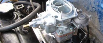
Float chamber of carburetor K-151
we install the machine on a flat horizontal platform (this is important since we will be working with liquid); dismantle the air filter housing located on the power unit; we start the engine, let it run at XX for about 5-7 minutes; unscrew and remove the top carburetor cover; measure the fuel level in the float chamber in millimeters. This operation should be carried out promptly, since gasoline is characterized by a high volatility rate, especially in the heat, which will also be facilitated by engine heating
By delaying, we risk getting distorted results; for K-151, measurements should give about 215 millimeters - this is an indicator considered normal for efficient engine operation; if the level does not correspond to the standard level, we perform an adjustment, which consists of changing the position of the float; To do this, we need to use something that allows us to measure the position of the float during adjustment work - the drill suggested at the very beginning, or a piece of wire, or any similar cylindrical object will come in handy. The main thing is that its diameter does not exceed two millimeters; turn the K-151 cover over and place it on a flat horizontal surface - only in this position will the measurements be accurate; Using a ruler, measure the distance from the carburetor cover (choose a cardboard gasket as a reference point) to the lower edge of the float. This distance should be no more than two mm; if this is not the case, you should bend the tongue of the float lever in such a way as to achieve the standard clearance.
The same operation can be performed using a caliper, but in this case you need to measure the distance from the cardboard spacer to the top edge of the float. The correct result is 30 millimeters. If there is a discrepancy, we again bend the lever tongue, achieving the required value.
Removing the K-151S carburetor cover
Please note that when making all the settings described above, there is a possibility of errors, especially if this is done by an inexperienced car owner. Therefore, after making the adjustment, you must check its correctness. This is done like this:
- move the K-151 cover to a vertical position;
- we monitor the tongue that we bent (or did not touch if the level was normal);
- If everything is done without errors, the tongue should lightly press and press the damping ball located on the IR. In this case, the lever tongue should be located at a level running strictly parallel to the needle valve;
- We also look at the float stamping axis, which should be located at a level coinciding with the carburetor cover.
If at least one of these conditions is not met, the procedure for adjusting the fuel level in the PC will have to be repeated. Many drivers limit themselves to two iterations, even if the situation requires otherwise. We recommend that you complete the setup properly, regardless of the time spent - the experience gained will definitely be useful to us!
From the very beginning of production, the Gazelle was equipped only with the ZMZ 402 engine, but since 1996, the ZMZ 406 engine began to be installed on the car as a series. The internal combustion engine was equipped with an electronic ignition system, but unlike the Volga, which already had an injector, the Gazelle had an injector. decided to leave the carburetor.
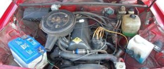
Engine installed on Gazelle 406
Assembly of the unit
Assembly is carried out in the same way, only the actions are carried out strictly according to the reverse dismantling scheme. It is necessary to replace the gaskets if their condition raises questions. Clean everything thoroughly using a special carburetor fluid or a rag soaked in gasoline.
It is recommended to start assembly with the jets, which just need to be put in place. It is important to decide on the primary and secondary cameras so as not to confuse the channels. Some tubes are short, others are long, this must be taken into account.
Here are some important assembly tips:
- The primary chamber can be immediately identified by the direction of the fuel spout towards it.
The fuel spout is always directed towards the primary chamber
An emulsion nozzle with 5 rows of holes is placed in the first chamber
The membrane must have an iron tip
The pump spring must be placed under the cover
Now important recommendations for installing hoses:
Fittings K-151 for connecting hoses
- A hose from the idle speed solenoid valve is attached to the lower carburetor fitting, number 6.
- A hose is placed from the valve onto the idle speed economizer into fitting 3. Otherwise it is called a vacuum intake tube.
- A hose from a distributor or vacuum regulator is mounted in output 7.
- K 5 - small crankcase ventilation hose.
The K-151 carburetor is considered a reliable device. However, it needs adjustment, disassembly and cleaning from time to time.
UAZ is a legendary car that has become famous not only among the military, but also among the civilian population. The plant really spared no effort and time on it. It is reliable, easy to maintain and repair, but requires constant attention, as it is a breeding ground for problems. One of the sore spots is the food system. Adjusting such a complex unit as the K151 carburetor on the UAZ Bukhanka is not a complicated procedure. However, it requires the correct technique. Today you will learn how to clean and tune, as well as adjust the carburetor to 151 on the UAZ.
Disassembling the carburetor K-151, K-151D
It is not recommended to unscrew the screws securing the throttle valves on the axles and remove the valves unless absolutely necessary, since their displacement can lead to jamming of the valves in the channels.
The brass connecting tubes of the channels pressed into the body should not be removed in order to avoid disturbing the tightness of their fit.
The carburetor should be disassembled only as a last resort if washing and blowing with compressed air without disassembly does not eliminate sticking of the throttle and air valves and does not lead to complete cleaning of the jets and channels from deposits.
1. Disconnect rod 1 of the air damper drive from the profile lever by removing cotter pin 2 from the hole at its curved end.
2. Remove the seven screws securing the cover to the body and remove the carburetor cover.
3. Unscrew the two screws securing the throttle body and, disengaging the connecting link, remove the body.
4. Unscrew the three fastening screws 1 and remove the cover 2 of the vacuum diaphragm of the carburetor starting device.
5. On the back side of the carburetor cover, remove the bent end of the carburetor trigger diaphragm rod from engagement with the trigger lever. Remove diaphragm 1 from the carburetor cover.
6. Disconnect tension spring 1 of the air damper from the cover pin. Unscrew the two fastening screws 2 and remove the cover 3 of the ventilation channel of the float chamber. Unscrew the fastening screw 4 and remove the econostat sprayer 5.
7. Unscrew the mounting screws and remove the starter drive levers.
Device
As with all carburetors, the tasks of this unit include preparing the fuel assembly (a mixture of air and fuel). Mixing must be carried out according to a clear and programmed scheme, otherwise the car engine will receive unbalanced power. The device must recognize the dissimilarity of power unit loads at idle, medium and optimal speeds.
Carburetor components:
- Housing with float chamber.
- Dampers controlled by an actuator integrated with the vehicle's gas pedal.
- A lid in which the design provides a locking mechanism and an air damper.
- The idle system is designed for stable operation of the engine in this mode. It, in turn, includes in the design a return channel, screws for settings with O-rings, jets, etc.
- The main dosing system (MDS) is necessary for direct mixing of fuel assemblies. Consists of channels for various purposes.
- The econostat is designed to enrich the fuel assembly when the engine is operating at its limit. In essence, this is a system of additional channels that supply additional portions of gasoline when the dampers are opened.
- An accelerator pump that allows the car to accelerate without any jerks or dips. A group of additional paths in a housing with a ball valve, a membrane and a fuel atomizer.
- The transition system is used to smoothly increase the speed. Refers to the secondary chamber, consists of separate jets.
Setting up the K-151 carburetor
Complex adjustment of the K-151d carburetor includes the following activities:
- adjustment of the float chamber (PC);
- adjustment of the starting device (PU);
- adjustment of the idle speed system (idle speed).
PC adjustment
First you need to remove the carburetor cover. At least a quarter of the fuel is sucked out of the float chamber using a rubber bulb. Then set the engine crankshaft to a position that blocks the movement of the fuel pump diaphragm. Start pumping the fuel mixture manually. Once the level stabilizes, stop the operation. The liquid mirror should be at a height of 3 cm from the upper edge of the middle part of the carburetor. To increase the fuel level to the required level, use a screwdriver to slightly bend the float tongue upward without removing it. To reduce the level, the tongue must be bent down. In this case, you need to hold the float so that it does not rise.
After making the adjustment, perform a secondary fuel level check. It must match the parameters recommended by the manufacturer. This setting does not need to be done regularly. The cause of the violation may be natural wear and tear of the device elements or unqualified intervention.
PU adjustment
The adjustment can be performed both on a removed carburetor and on the device located in its standard place in the car.
Adjusting the PU on a previously removed carburetor. First, you need to slightly open the throttle by turning it all the way and locking the trigger control lever. Then we release the shutter and, using a drill or other tool, check the gap between the edge of the damper and the chamber wall. It should be within 1.65 ± 1.5 mm. To correct this gap, first unscrew the lock nut and then rotate the stop screw. It must be remembered that for correct operation of the mechanism, the plane of the screw head must always be in a position perpendicular to the plane of the cam. In other words, the screw should be rotated in multiples of half a turn.
Following this, we adjust the thrust, which connects the air damper axis to the PU control lever. When the damper is fully closed, the gap between the levers should be 0.5 ± 0.3 mm. If necessary, increase or decrease the length of the rod by rotating its head.
At the next stage, we check the gap if there is a vacuum. Without releasing the PU control lever, use a screwdriver to recess the rod and measure the gap at the lower edge of the damper. Its value should be within 6.5 ±0.5 mm. If necessary, adjust the gap by rotating the screw, which tightens the halves of the PU lever.
Adjusting the PU on a car. First, remove the air filter and start the engine. Then gently press the gas pedal and pull the throttle control lever towards you as far as possible. At maximum opening of the air damper, the engine speed should be within 2600 ±1000 rpm. If the rotation speed goes beyond these limits, unscrew the locknut and turn the stop screw of the first chamber remote control lever in one direction or another until the required speed is reached. After this, tighten the locknut.
Note. Due to the difficult access to the screw, experienced drivers perform this adjustment by carefully bending the PU control lever.
Service
Carburetors are reliable and unpretentious devices. K-151, like other components in the automotive system, requires periodic maintenance. Basically, problems arise in the event of unqualified intervention in its design or due to inappropriate maintenance. Neglecting the simplest maintenance procedures for the K-151, it may happen that the carburetor ceases to function fully due to the clogging of the calibrated holes with hard tarry deposits. For its correct operation, it is necessary to timely adjust the main systems.
Idle speed adjustment
The design of the K-151 does not allow dirt and dust to penetrate directly into the unit; in addition, during its operation, due to the movable joints, self-cleaning of the most important functional elements occurs. A simple but extremely effective layout allows even a dirty K-151 carburetor to work no worse than an absolutely clean copy. But at least 1-2 times a year you should clean it from the outside using compressed air. This is the minimum required maintenance for the device. Don't forget about adjusting the most important systems.
Adjusting the XX on the K-151 carburetor is necessary for normal engine operation. A properly operating engine contributes to the formation of a minimum amount of carbon monoxide in the exhaust gases. Since most car enthusiasts do not have even the most ordinary gas analyzer at their disposal, monitoring the operation of the system is not so easy. But there is a way out of this situation - it’s enough to arm yourself with one tachometer.
The procedure is as follows:
- Initially, the engine warms up, then the quality screw rotates until the maximum idle speed is established. In this case, the quantity screw remains in the same position.
- Afterwards, the speed is set to exceed the initial value by 100-120 rpm.
- It is recommended to do the above steps twice to be on the safe side.
- Then the quality screw is tightened until the speed reaches a normal value.
It is especially effective to adjust the idle speed if you have a high-precision tachometer. Such work can be carried out at any time, but it is most advisable to do it two or three times within one year.
Adjusting the float mechanism
Any carburetor adjustment must include adjusting the float mechanism - a responsible and extremely important task. But no difficulties in carrying out such work should arise even for those who have only recently become owners of a car with a carburetor power system. However, it is worth understanding that any inaccuracies in the adjustments can lead to further interruptions in the operation of the power system
That is why it is important to prepare thoroughly before starting to manipulate this mechanism.
Procedure:
- The upper part of the housing is removed.
- About a quarter of the fuel is pumped out.
- The crankshaft is installed in such a position that nothing interferes with the movement of the fuel pump diaphragm.
- Gasoline is pumped in manually.
- Once the required fuel level is set, the shank of the caliper with the height set at 21.5 mm is lowered between the wall and the shut-off needle.
When adjusted, the shoulders of the caliper will rest against the top of the body, and the shank will come into contact with the fuel. At a low level, the tongue must be bent upward, and at a high level, accordingly, downward.
It is important to drain the fuel from the chamber each time after changing the position of the tongue.
K-151 D
For Gazelle cars with a ZMZ-406 engine, the manufacturer has provided a separate carburetor. It differs from the element for the Volga with a 402 engine. Carburetors also had different markings. For the Volga the marking was K-151 C, and for the Gazelles it was K-151 D. Externally, both models of carburetors had no differences. There is a slight difference in the design, the rating of the jets and other technical nuances.
In the Gazelle carburetor, the accelerator pump nozzles supply fuel to two chambers, while for the Volga the accelerator pump operates only in the first chamber.
What are the disadvantages of this mechanism? The problem with this carburetor with the 406 engine is the huge fuel consumption. This is especially noticeable when the car is loaded (which is important for Gazelles) and moves at a speed of more than 60 kilometers per hour. This problem exists, and it is widespread. Owners of commercial vehicles are trying to solve it in any possible way.
Among the owners it is believed that this model is very capricious. The unit is not suitable for everyone; many often abandon this device in favor of other models.
Additional analogue features
Setting up a VAZ-2109 carburetor with your own hands
The K151s carburetor also has:
- New small diffuser device. The mass production market is characterized by more stable performance. Promotes high vacuum.
- Acceleration pump. Its peculiarity is the output of nozzles into both chambers.
- The starting drive mechanism is stepless type. In start-up and warm-up mode, it promotes more flexible engine control. Eliminates the need to press the gas pedal before starting a cold engine.
- Modernized adjustment of dosing elements. Responsible for ensuring the best driving performance of the car, subject to compliance with exhaust gas toxicity standards.
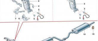
Connecting hoses
The complex structure of the K-151 is also evident when it is connected to the engine. It provides for the use of a whole range of hoses, but only two different sizes are used, so it is quite possible to confuse them, and the motor will malfunction in certain modes. The order of connecting the hoses to the carburetor:
Fuel is supplied through the fuel pipe to a fitting located under the float chamber on the engine side; the return hose is put on the lower fitting - it looks in the direction opposite from the power unit and is located below the inlet; two small cross-section hoses are connected to the solenoid valve, the other end of one of them is connected to the economizer valve; the second end of the thin hose is put on the fitting located in the lower part of the K-151 on the back side of the DZ body (there are two of them standing next to each other, we use the lower one); onto the upper fitting of this pair we pull the hose that goes to the vacuum ignition advancer (it is located on the distributor); a large diameter fitting on the DZ housing is used to connect the forced crankcase ventilation pipe, a device usually located on the valve cover; a small diameter fitting located in the middle part of the K-151 is used to connect a thermal vacuum switch, however, this pipe is used only if the engine has an exhaust gas recirculation system. If such a system is not provided for a specific modification of the motor, simply install a plug on this fitting
True, such a precaution is unnecessary - there is no air leak through this fitting.
If you lack experience, these connections should be made by consulting the instructions for the device.
Connecting carburetor hoses K-151D
Repair
During the operation of the car, various malfunctions may occur in the carburetor; the main signs of malfunctions in this device are:
- increased fuel consumption;
- black smoke from the muffler pipe, it is especially noticeable if you press the gas pedal sharply;
- unstable operation at idle, the engine may also stall when the speed is reduced;
- poor car dynamics;
- failures when accelerating.
If the carburetor is faulty, the engine may not develop speed, and popping noises and shots from the muffler are often heard in the intake manifold. K-151 is a rather complex unit, and almost any element of it can fail.
There are reasons why a carburetor most often fails:
- jets, fuel and air channels become clogged;
- heating causes deformation of the body;
- the float chamber shut-off valve stops working;
- Over time, the jets wear out.
Many repairmen, when restoring the functionality of the carburetor, first of all try to replace the jets, believing that because of them fuel consumption increases and the engine runs unstable
One rather important note - the jets wear out very rarely, and most often wear occurs when the carburetor is often operated in dusty conditions. The most common reason for poor carburetor performance is its clogging, but in order to thoroughly clean the unit, it is necessary to completely disassemble it
Repair of the K-151 carburetor is carried out with the removal of the device, complete washing and purging of all its parts.
Problems with the carburetor when installing HBO
Most car owners with carburetor engines in their cars convert them to use gas equipment. For example, you can take Gazelle. But there is a big disadvantage of using gas equipment - when gas is frequently used at the carburetor, unexpected situations begin to occur. And the most famous cold start problem. On most cars, a spacer is made in the HBO for it on the K-151. It is placed between the main and throttle valves. This increases the space between the top and bottom of the carburetor. In this case, disturbances occur in the starting system when the engine is not preheated. In this case, the driver has to continuously hold down the gas pedal and the choke with his foot. Gas equipment has no relation or influence on the operation of the engine and a poorly functioning choke.
The fact is that in winter a cold start of the engine must be done on gasoline. It is difficult to start an internal combustion engine with the air damper not tightened tightly. When strong vibration is created, the axial fastening sometimes becomes unscrewed.
How to resolve identified problems
Solution methods:
- Weld an additional strip onto the air damper rod. This will help compensate for the difference in thickness of the conventional gasket between the body and the gas spacer;
- Making a strip from a microcircuit (electrode) 2 mm thick.
Tuning
A simple modification can optimize its operation and significantly extend its service life. To do this, perform the following operations on a cold engine.
- The fuel nozzle plug is unscrewed from the carburetor.
- The jet itself is removed from the socket using a thin copper wire.
- The jet is removed from the solenoid valve.
- The hole in the nozzle increases by 0.05–0.1 mm, depending on the modification.
- The modified jet is screwed onto the valve.
- The removed device is returned to its place.
Increasing the flow rate of the jets improves vehicle dynamics
In this case, it is necessary to replace the rubber valve seal. The solenoid valve gasket is the most vulnerable point of the K-151 series carburetors.
Increasing the capacity of the fuel nozzle will significantly improve the dynamics of the car.
The air jet can be modified in the same way.
Gazelle
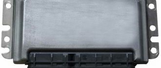
Model ZMZ 40524.10 is a gazelle carburetor known to everyone. The car brand “Gazelle” is one of the most popular and affordable trucks in Russia, which were originally intended for transporting not very large loads. Due to the huge number of such machines, we will consider several nuances of different gazelle systems. For example, a microprocessor ignition system, which is installed on the 406 model.
If the driver claims that his car makes some popping noises, jerking noises and loses its power. In this case, the power system, engine and ignition system should be checked. We checked the carburetor with a gas analyzer not during the operation of the 1st and 2nd chambers, cutoff, enrichment and during idling and did not find any violations. Next they check the engine. When checking the compression, no problems were identified, but the next time deviations from the norm were detected. It was concluded that the jerks and pops that the driver did not like were due to the jumping of the teeth of the upper chain.
Carburetor ZMZ 406 series
What to do if a gazelle loses power?
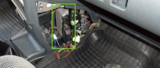
From the very beginning, you need to check how the diagnostic circuit and the on-board diagnostic system function, because when the travel image mode is activated, a malfunction code of 12 should be obtained. To read the code, the 10th and 12th contacts of the diagnostic block must be closed. Using a diagnostic toaster, engine sensor parameters are measured and then compared with typical values for average engines. The most common reason for a decrease in car power is contamination of the tube that connects the intake manifold and the pressure sensor.
Gazelle ignition system
The microprocessor ignition system ignites the working fluid in the cylinders and sets the required vehicle ignition timing for all engine modes. The ignition system performs the function of regulating the operation of the forced idle economizer. Thanks to the ignition system, engine operation becomes more economical, compliance with all exhaust gas toxicity standards is monitored, detonation is eliminated and the vehicle's power is increased. If we compare the classic system with this one, then this ignition system is much more reliable and durable. Here only the spark plugs can wear out.
Blog about UAZ
About the book: Guide. Edition 2003. Book format: pdf file in zip archive Pages: 76 Language: Russian Size: 9.3 mb. Download: free, without restrictions and passwords
Carburetor K-151. Device, adjustment, repair.
The book examines the design and operation features of automobile carburetors of the K-151 family produced by PEKAR OJSC. The main characteristics and parameters of carburetor components and systems are given. The features of operation and maintenance of carburetors and related vehicle systems - forced idling economizer and toxicity reduction - are outlined.
Recommendations for detecting and eliminating typical faults are given. Provides instructions for disassembling, assembling, diagnosing, adjusting and repairing carburetor components and systems. Color illustrations contribute to a better understanding of the material.
Carburetors of the K-151 series are made according to general standard designs, but in design they are fundamentally different from the widely used carburetors of the Weber, Ozone and Solex types and have practically no common parts with them. The need to create carburetors of the K-151 series is caused by the expansion of the model range of the Gorky and Ulyanovsk Automobile Plants, the cars of which are equipped with engines from the Zavolzhsky Motor Plant (ZMZ).
Compared to previous models of carburetors of OJSC PEKAR, carburetors of the K-151 series provide better mixture formation and accurate fuel dosing in all operating modes, which sufficiently meets the requirements of existing and future exhaust gas toxicity and fuel efficiency standards.
OJSC PEKAR produces the basic carburetor of the K-151 series and seven of its modifications - K-151V, 151G, 151E, 151I, 151D, 151P and 151N, intended for installation on four-cylinder ZMZ engines of GAZ cars, UMZ - UAZ cars and UZAM - cars Izh.
All modifications of carburetors of this family are of the same type: two-chamber, two-diffuser with a falling flow of the combustible mixture and pneumatic fuel braking, a balanced float chamber, elements of a closed crankcase ventilation system and sequential opening of the throttle valves. They differ mainly in calibration data and sets of additional elements.
Carburetors of the K-151 series are equipped with a single-section float chamber with a hollow brass float; autonomous idle system (ASXX); main dosing systems in the primary and secondary chambers, transition system of the secondary chamber; control vacuum selection systems for the vacuum corrector of the ignition distributor and exhaust gas recirculation valve (not on all modifications); valve for shutting off the fuel supply in forced idling mode (FID); mechanical drive of the throttle valve of the secondary chamber; diaphragm mechanism for starting and warming up a cold engine with a manual air damper drive; econostat; diaphragm accelerator pump.
Modifications K-151V and K-151G are designed for engines of the UMZ-417.10 family with a displacement of 2.45 liters. UAZ-31512, 31514, 3741, 3962, 2206, 3303, 3909 cars. They differ from the base carburetor, and from all other modifications of the family, in calibration data, the presence of an electrically driven float chamber unbalance valve, the absence of fuel return fittings and control vacuum selection for EGR valve.
Both modifications have the same calibration data and differ only in the design of the throttle valve drive: the K-151V modification has a lever installed on the axis of the throttle valve of the primary chamber for connecting to the accelerator pedal using a rod system; the K-151G has a sector for connecting a flexible cable instead of a lever.
Adjusting the K-151 carburetor
The adjustment procedure is not particularly difficult, but if you have no experience, it is better to study the adjustment of the K-151 carburetor in the video:
The old Soviet school of carburetor construction ensures that the K-151 or K-151E can be repaired and adjusted using a simple or Phillips screwdriver.
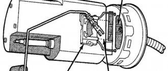
Monitoring the level of imbalance of the float chamber K-151
For normal operation, a properly functioning valve is required to compensate for the air pressure in the float chamber. If problems arise with the operation of the balancing valve, fuel consumption jumps sharply, and it is useless to adjust it. At the same time, the click of the drive does not at all indicate pressure balancing; before repair, it is better to check by replacing it with a known-good version. For further adjustments of the K-151, you should first clarify and adjust the fuel level in the float chamber.
Setting idle speed K-151
We carry out a simple procedure for setting idle speed in the following order:
- warm up the engine to operating temperature;
- Using a screwdriver, we display on the tachometer the position of idle speed 550-650 (for a three-liter 700-750). the large screw is easy to see on the rear wall of the carburetor;
- Use the screw to set the air-fuel mixture composition - turn the engine speed up to maximum;
- use the idle speed adjustment screw to raise the idle speed by a hundred more than necessary;
- Use the mixture quality screw to set the required idle speed K-151.
Let's work with the throttle position screw
The carburetor design uses a thrust screw for adjustment and repair, which limits the extreme position of the damper. The thing is very useful, but there is a nuance. The screw tends to self-tighten, thereby leaving the damper suspended. The damper begins to rub against the walls of the chamber and after a certain period of time wedges in the extreme position.
To prevent this situation, after adjustment, the screw should be secured with a drop of paint.
If you have good mechanic repair skills and a desire to “sharpen” and adjust the K-151 carburetor to suit your car, choose K-151S. Otherwise, the old, reliable K-126G, or for vehicles with off-road properties with the GU index, will do.
Malfunctions and their elimination
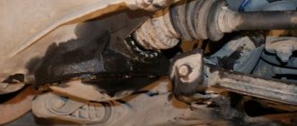
Freezing of the economizer housing
The K-151 carburetor on some engines has one unpleasant feature. In humid subzero weather, the fuel mixture in the carburetor actively condenses on its walls. This occurs due to the high vacuum in the channels at idle (the mixture moves very quickly, which leads to a decrease in temperature and the formation of ice). The economizer body freezes first, since air enters the carburetor from here, and the flow cross-section of the channels here is the narrowest.
The trunk of the air intake hose can be thrown directly to the manifold. Or make a so-called “brazier” - a heat shield made of a metal plate, which rests on the exhaust pipes and to which the air vent hose is connected (see figure).
"Brazier"
Also, in order to reduce the risk of the economizer freezing problem, before the trip we warm up the engine to an operating temperature of 60 degrees. Despite the thermal insulation gasket from the engine, the carburetor still receives some heat.
Flange straightening
With frequent disassembly and removal of the carburetor, as well as with excessive force when tightening the flange to the engine, its plane may be deformed.
There are many ways to solve this problem. But the simplest and most accessible method is the following:
- We heat the plane of the carburetor flange using a gas burner. First, we remove all the components and parts of the carburetor (fittings, levers, etc.).
- Place the plane of the float chamber on a flat surface.
- As soon as the carburetor heats up, place a thick, even piece of hard metal on top of the flange. We don’t hit the piece too hard, moving it to different places each time. Basically, the bending of the flange occurs along the edges, in the area of the bolt holes.
Useful video
For more information about the method of straightening a flange, we recommend watching this interesting video:
To prevent further bending of the flange, simply tighten it evenly once to the engine and do not remove it again. As we saw above, the carburetor can be cleaned and adjusted without removing it from the engine.
Description of design
The K-151D carburetor, installed on a car with a ZMZ-4063 engine, has two adjacent vertical channels (chambers) for the passage of air, in the lower part of each of which a rotary throttle valve is installed.
The throttle valve drive is designed in such a way that as you press the accelerator pedal, first one valve and then the other opens. The chamber in which the throttle valve opens earlier is called the first, the other is called the second. In the middle part of each of the main air channels there are cone-shaped constrictions-diffusers, which create a vacuum in the air flow necessary for sucking fuel from a special container located in the carburetor body - the float chamber. The fuel level in the float chamber required for normal operation of the carburetor is maintained using a mechanism with a float and a needle valve. The carburetor float mechanism is completely located (together with the needle and float) in the carburetor body and is accessible for visual inspection after removing the cover (the fuel level in the float chamber can be measured without removing the float). The carburetor consists of three main parts: the top - the housing cover, with a flange and studs for fastening the air filter housing, with a float chamber ventilation device and starting device parts. The cover is attached with seven screws to the carburetor body through a cardboard gasket; the middle one - the carburetor body, with a float chamber and float mechanism, fuel supply fitting and fuel metering systems; the bottom - the throttle body, with the throttle valves and their drive mechanism, as well as an idle device attached to the carburetor body from below with two screws through three gaskets (two thin - cardboard and one thick - plastic). The carburetor has the following systems, devices and mechanisms: float mechanism; fuel metering systems; main dosing systems of the first and second chambers; idle system; transition system of the second chamber; econostat; accelerator pump; starting device economizer valve for shutting off fuel supply in forced idling mode (EFH); crankcase ventilation system; float chamber ventilation system; throttle valve control mechanism. The idle system is autonomous, with adjustment of the mixture composition. In the second chamber of the carburetor there is a transition system with fuel supply directly from the float chamber, which comes into operation when the throttle valve of the second chamber is opened. A diaphragm-type accelerator pump, which comes into operation when the accelerator pedal is sharply pressed. To enrich the combustible mixture at full load, an econostat is provided in the second chamber. The starting device is a semi-automatic type, consisting of a pneumatic corrector, a system of levers and an air damper, which is closed before starting a cold engine using a manual drive. At the moment of starting the engine, the pneumatic corrector, under the influence of vacuum arising in the intake manifold, automatically opens the air damper to the required angle, ensuring stable operation of the engine when warming up. The fuel supply cut-off system (forced idle economizer) comes into operation in forced idle mode when the vehicle is braking by the engine, when there is no need to supply fuel to the engine. This ensures fuel savings and reduces the emission of toxic substances into the atmosphere. Calibration data for carburetor K-151D
| Options | First camera | Second camera | |
| Main fuel jet* | 225±3,0 | 340±4,5 | |
| Main air jet* | 330±4,5 | 330±4,5 | |
| Idle system jet block with emulsion tube*: | fuel jet | 95±1,5 | – |
| air jet | 85±1,5 | – | |
| Idle air jet | 425±6 | – | |
| Emulsion jet of idle system* | 280±3,5 | – | |
| Transition system fuel jet* | – | 150±2,0 | |
| Air jet of transition system* | – | 270±3,5 | |
| Diameter of the hole in the screw holder of the econostat atomizer, mm | – | 2+0,06 | |
| Diameter of the fuel bypass hole into the tank, mm | 1,1+0,06 | – | |
| Fuel valve seat diameter, mm | 2,2+0,06 | – | |
| Diffuser diameter, mm: | small | 10,5+0,1 | 10,5+0,1 |
| large | 23+0,045 | 26+0,045 | |
| Accelerator pump performance for 10 full strokes, cm3 | 10±2 | ||
| Fuel level from the top edge of the housing, mm | 21,5+1,5 | ||
| * The table shows the markings on the jets indicating the error in measuring their throughput. |
Idle systems
K-151 have an autonomous idle system, which is a miniature carburetor. The throttle valve is almost completely closed at this time, the gap between it and the walls is minimal; this should not create a vacuum in the tube of the vacuum ignition timing regulator. The autonomous system ensures good atomization of fuel and uniform distribution of the mixture among the cylinders (by composition), which allows the air-fuel mixture to be leaned to a ratio of 1:15. As a result, it is possible to reduce the concentration of CO in the exhaust gases to 0.3–0.6% (usually regulated with a certain margin - 0.7–1.1%), and CH to 180–230 ppm. Regulation is carried out mainly with the mixture quality screw.
In forced idle modes, including engine braking and slowing down the crankshaft, the membrane mechanism displaces the forced idle economizer valve until it stops, closing the outlet and stopping the fuel supply. The use of an autonomous system with EPH reduces CO and CH emissions by 30–40% and, when tested in the urban cycle, reduces fuel consumption by 4.5%, and also increases engine braking efficiency by approximately 25% (these are “official” or “textbook” values effectiveness of EPHH - Ed.). EPHH also performs the “anti-diesel” function, i.e. With low-octane gasoline, self-ignition is prevented after the ignition is turned off.
In K-151, fuel from the main metering system channel rises to the emulsion tube with fuel and idle air jets. Having passed through the side holes in the tube and the emulsion jet, it is mixed in the form of a fuel-air emulsion with additional air entering through the second air jet. To ensure stability of the mixture composition when regulating the quantity with a screw in the lower part of the carburetor body, the idle system has two channels. According to the first of them, the emulsion enters the cavity in front of the vias through the adapter sleeve, and then through the cross section, adjusted by the lower quality screw, into the main diffuser with the quantity screw. Through the second channel in the carburetors of the first releases, the emulsion passed through a cross section controlled by an additional (upper) quality screw. In the latest arburetors, this screw is replaced by a metering hole in the channel. Next, the emulsion enters an additional diffuser in the throttle body.
The EPHKH K-151 valve control system (for “402” engines - Ed.) consists of an electronic unit that turns on an electro-pneumatic valve when the crankshaft speed decreases below the set one and turns it off when they increase above 1,500 rpm, and microswitch. In the operation of any carburetors, the greatest number of failures occurs in the idle system. This is not surprising - after all, its fuel nozzle has a very small cross-section. Therefore, if the idle speed “disappears”, then it is the first candidate for purging. True, before disassembling the carburetor, it makes sense to carry out simple diagnostics.
You need to remove the wire ends from the microswitch and close them. If the engine starts, it means the electronic unit has failed. Temporarily, until it is replaced, you can drive by insulating the shorted wire tips. If the engine does not work even after closing the tips, remove the hose coming from the throttle body and connect it directly to the EPHH membrane mechanism. The engine starts idling, which means it is necessary to replace the solenoid valve. If the engine does not work again, then it is necessary to remove the diaphragm mechanism cover and check whether the valve moves freely and whether the diaphragm is not torn. If the diaphragm is torn, you can cut off a piece of the hose, cut it lengthwise, slide it under the diaphragm and put it on the valve stem. If the engine is unstable or stalls during the initial period of opening the throttle, then adjust or replace the microswitch. It should close the contacts at the very beginning of turning the throttle lever.
The electronic unit can be checked by connecting to it, instead of the wire going to the electro-pneumatic valve, a light bulb with a power of no more than 3 W. The other wire from the light bulb is connected to ground. The wire from the microswitch must be disconnected. When the speed increases above 1,200–1,500, the light should go out, and when it drops to 900–1,000, it should light up again. In this case, the block is OK.
Fuel consumption – according to factory standards and real
According to technical passport data, fuel consumption at a speed of 60 km/h with the ZMZ 4063 and ZMZ 4061 engines is 10.5 liters, at a speed of 80 km/h – 13 liters. But during control measurements many factors are not taken into account:
- Car load;
- Weather;
- Road conditions;
- Technical condition of the car.
These standards can be met if the car is operated in the summer on a dry road, without a load and in fully working order. Much still depends on driving style. The harder the driver presses the gas, the more fuel is consumed. Gasoline consumption also depends on its quality. It has been noticed that fuel with a higher octane number is consumed less. Therefore, for the Gazelle it is preferable to fill with AI-95 fuel instead of AI-92.
Comparison table for fuel consumption in various modifications of the Gazelle car
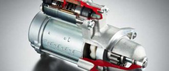
How to remove the K 151 Pekar carburetor on an UAZ?
To do this, you need to go into the car's interior in the driver's or passenger's seat in the front and open the engine compartment hatch. The next step is to remove the air filter. To do this, first unscrew the upper fastening nuts, after which the filter element itself is removed. Be careful not to drop the nuts into the diffuser!
Now unscrew the nuts securing the filter housing. Lift it up, disconnect the thin hose and set the housing aside. Now disconnect all the linkages associated with the throttle valve. To avoid breaking the plastic elements, it is recommended to use a flat-head screwdriver.
Unscrew the fastenings of all hoses holding the unit and remove them. There will be four nuts that hold the carburetor to the manifold. Unscrew them and remove the unit.
Still have questions about withdrawal? Let's watch this video:
This is interesting: How to bleed a clutch: let’s break it down point by point