What to do if there is no light in the house? A current generator can help solve the problem. But if this equipment also fails, checking the generator with a multimeter will help determine the malfunction. Regardless of the type and brand, with the help of this device, once you find out the cause of the malfunction, you can carry out simple repairs yourself.
There are many types of generators, from large and powerful industrial devices to small automotive devices. But the testing algorithm using the tester is the same for any generator.
What components and parts are checked using a multimeter?
This operation involves diagnosing the electrical part, and checking the following parts:
Voltage measurements are taken at the generator output;- the rotor excitation winding is checked for open circuit or short circuit to the housing;
- checking the stator windings for breakdown and open circuit;
- carry out fault detection of the diode bridge, capacitor;
- faults in the voltage regulator and brushes are detected;
Performing each of the listed operations requires special knowledge and skill to carry out measurements, so each test should be considered in more detail.
Do-it-yourself generator repair, maintenance and replacement
Good maintenance, which any car requires, will allow it to serve its owner for many years without serious problems. You just need to monitor the serviceability of the main components and systems. These include a converter of mechanical energy into electrical energy. Replacing and repairing car generators is one of the main operations of service center workers.
After all, without power supply, the comfort of the vehicle disappears, and it turns into a horseless cart made of stamped metal. The generator rarely stops functioning immediately. It usually gives the owner signals for quite a long time by “winking” its sensor in red and making noise from under the hood. You must carefully study the operating manual of the machine.
Weak or overcharging of the battery is also a symptom of its suffering. Checking it will show a number significantly less than 13 Amps on the multimeter. Then you need to seek help from specialists. Although, if a car enthusiast feels sufficiently prepared and experienced to try to find and fix the breakdown on his own, then he can begin to master the profession of a car mechanic.
Of course, technologically repairing generators is not difficult, but it is better to stock up on a sufficient set of tools and enlist the support of a friend experienced in this matter. The soldering skills of at least one of your friends will be very useful. Otherwise, you will have to invite a third one. You can start the event. It should be led by the most experienced member of the team.
Preliminary identification of the cause of the breakdown
- Noise during operation indicates wear of the bearings. If one bearing breaks, it will make a small sound. If two bearings are involved, the generator will rumble.
- The regulator indicator flashes red and charging is normal. Most likely, the relay in the electrical circuit is broken.
- Insufficient battery charge can be explained by worn-out or broken brushes, diodes, relays, or voltage regulator. Or there is a short circuit in the windings of the unit.
Output voltage level measurement
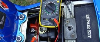
For each individual unit this value will be different. Let's take a closer look at checking a car generator. Set the voltage measurement mode on the multimeter scale. First you need to check the voltage with the engine turned off. To do this, measure the voltage value at the battery terminals.
We connect the red probe to the positive terminal, and attach the black one to the minus terminal. A charged, serviceable battery will produce a value of up to 12.8 V. We start the engine. Then we take a measurement.
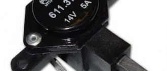
Now this value should be no more than 14.8 V, but no less than 13.5 V. If the voltage level is higher or lower, the generator is faulty.
Diode bridge
The diode bridge consists of six separate diodes: half of them are positive, the other half are negative. It is necessary to select the “Dial” mode on the multimeter. After this, as soon as the contacts on the tester close, a soft beeping sound will be heard. You need to check in both directions. If a squeak is heard in both cases, then this indicates a breakdown of the diode. Therefore, it needs to be replaced.
Checking the rotor winding
To perform this operation, it is necessary to dismantle and disassemble the unit. When performing a self-test, do not forget to set the device to the circuit resistance measurement mode.
Additionally, a value of no higher than 200 Ohm is set. These routine maintenance works are carried out in 2 stages:
- Measuring the resistance value of the rotor windings. To do this, we attach the probes to the rings of the moving part of the engine and determine the value. This will make it possible to determine the probability of a winding circuit break at a value above 5 ohms. If the device shows less than 1.9 ohms, a turn short circuit has occurred. Most often, the chain breaks at the junction of the rotor winding lead to the ring. You can determine the defect by moving the wire with a probe at the soldering points, as well as by detecting darkened and crumbling wire insulation. In the event of a break or short circuit (short circuit), the wires become very hot, so the breakdown can be detected by visual inspection.
- A circuit test is performed to detect a short circuit to the frame. We position the generator rotor conveniently for operation. Then we bring one probe to the rotor shaft, and attach the second to any ring. If the winding is working properly, the resistance reading will go off scale. If it shows low resistance, this part should be sent for rewinding. When rewinding the rotor, it is important to maintain perfect balancing.
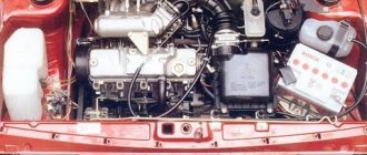
Design and basics of operation
A gasoline generator is a device that runs on liquid fuel. Its task is to convert the mechanical energy of the engine into electrical energy, which is produced by the alternator. These are two main nodes that are interdependent. Repair of gasoline generators is most often associated with the maintenance or replacement of elements that are part of the engine and alternator or are functionally connected to them.
Equipment design
The engine is equipped with a number of systems: starting, shaft speed stabilization, cooling, exhaust and air supply. This unit is driven most often in two ways:
- By hand pull;
- Electric starter.
In more functional models, the engine is started by autostart. If it is quite possible to repair autonomous gas generators of a mechanical starting system yourself, then understanding the automation is much more difficult.
There are single-stroke and four-stroke models of alternators (generators). In gasoline mechanisms, the second of these are most often used.
Checking the stator windings
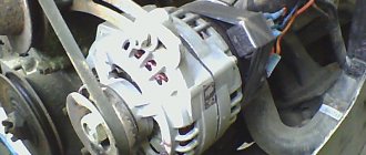
Checking the stator begins with a visual inspection. We pay attention to external damage to the housing and insulation, and places where wires are burned during a short circuit.
The faulty unit should be rewound or replaced. If the external integrity of the wires is established, we begin to investigate using a tester.
Before starting work, you should make sure that the unit is disconnected from the network and that there is no contact between the leads of the stator windings.
When performing work to check the normal state of the node, we make sure:
- The integrity of the winding circuit. To do this, set the device to resistance measurement mode. We attach the probes to the first pair of terminals, then check the 1st winding and the 3rd, 3rd and 2nd terminals. If, during a break, the pointer of an analog device goes off the scale, the windings should be rewinded.
- In the absence of an interturn short circuit and to the housing. To do this, connect one of the tips to the terminal, the second to the body. If the windings are short-circuited, the scale will have a lower resistance value than those in good condition.
How to test a generator with a multimeter
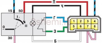
However, first of all, without removing the rectifier bridge from the alternator, connect the red test lead to terminal 30 of the alternator, and the black lead to the housing. Set the tester operating mode to diode (diode icon). If it is not there, set it to 1-2 kOhm. The multimeter should show infinity. If the readings are different, the diode bridge is faulty.
Then check that the rectifiers are not damaged. Leave the positive sensor (red) on terminal 30 and the negative sensor in alternate contact with the jumper mounting screws. The multimeter indication should indicate infinity in all cases, each other indicating a failure.
Then connect the positive sensor to the axle mounting bolts and the negative sensor to the generator housing. In this case, the tester should also give infinity.
However, in practice such verification is usually not enough. In most cases, it is necessary to perform a more detailed check of the generator.
To do this, unscrew the screws securing the rectifier unit, disconnect the copper wires of the stator winding and remove the diode bridge from the generator. Now you can test each semiconductor separately. Before checking, it is recommended to rinse the stabilizer under running water using a medium-hard brush, and then dry thoroughly. A hairdryer is good for quick drying.
Careful testing
Attach one of the tester probes to the diode board, and connect the other probe to the center contact of each diode attached to the board. Then swap the sensors. In one case, the multimeter should show infinity, in the other - a nominal resistance of the order of 570-590 Ohms. Rectifiers are considered faulty if:
In the first and second measurements (with reverse polarity), the multimeter readings coincide;
- The diode resistance is greater or less than the nominal values.
- Do the same with the second plate of the diode bridge. If one or more diodes fail, it will be easier to replace the entire rectifier assembly. True, there are craftsmen who replace damaged diodes separately, but such work requires a certain skill and dexterity.
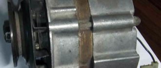
The generator must be completely disassembled for further testing. First of all, you should visually check the fittings. Brush rings should be free from darkening, spattering and raceway wear. Black spots and minor signs of wear can be removed with a cloth. Rings with deep grooves must be replaced or, if the thickness of the ring allows, turned on a lathe.
Checking the armature and stator windings
The armature winding should not have a distinct burning smell. The color of the winding must be uniform, without damage or tears. A multimeter is needed to check the armature winding for gaps. Set it up to test or measure resistance and connect the probes to the brush rings. The winding resistance should be within 3-5 Ohms. Then leave one probe on the ring and connect the other to the body. The multimeter display should show infinity.
The generator stator is diagnosed outside the housing. First perform a visual inspection. There should be no visible damage to the cable and its insulation. Then connect the probe to the stator housing. Touch the terminals one by one with the other wire. There are three of them in total. The tester must be in test mode. If the display shows infinity, the stator is OK.
A further check is the diagnostics of the windings. The resistance of all three windings must be the same.
Before reinstalling the generator, check the bearings and replace if necessary. They should not jam or squeak when turning. This means that they are very worn and will soon fail. Therefore, it is better to replace them immediately.
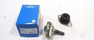
Voltage Regulator Troubleshooting
Remove and disconnect the wires from the part. We inspect the condition of the brushes. They should not have significant defects or chips. In the guide channels of the brush holder, the generator brushes must move freely. If they protrude beyond the edge by less than 5 mm, the generator regulator should be changed.
The test is carried out using batteries and a 12-volt light bulb. The voltage of the second power source must be at least 15 V, so we connect the batteries in series to the car battery and adjust the value to the desired value. We attach the plus from the 1st power source to the output contact, and the minus to ground.
The light bulb is installed between the brushes. When connecting a 16 V source, it should not light up. With a weaker battery, it lights up. If proper combustion is not observed, the regulator should be replaced.
Slip ring block
Disassembling the generator is the first thing to do.
In order to see the rings, it is enough to remove the back cover of the gene from the side of the diode bridge. However, to replace it you will need to disassemble the entire device. A block of rings is like this.
The rings, as you can see, come assembled. Factory rings have a decent thickness - 1-2 mm. Purchased analogues may be thinner. Blocks of rings “run” on generators, depending on operating conditions, for approximately 300 thousand vehicle kilometers. If the generating device did not fall into the area of primary concern of the car owner, and “lived out its life,” so to speak, in oil, the service life of the slip rings will decrease significantly.
The block is inexpensive. If you replace it along with the bearings and the tablet, you get an almost brand new generator.
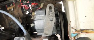
We independently check the generator on the “Ten” at home
On any modern car, the generator device performs the important function of powering the battery and all electrical devices while driving. Like any other component, this device can fail over time. In this article we will tell the owners of the “ten” how to properly check the generator on a VAZ 2110 with their own hands.