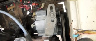
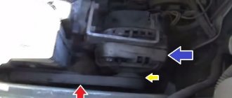
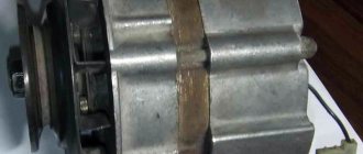
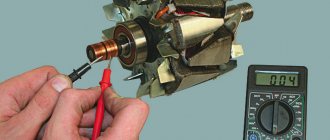
The correctness and stability of the operation of all vehicle electronics depends on the serviceability of the generator, because it powers all devices after the engine starts. Therefore, it is important to maintain the generator in “combat” condition, which means servicing it correctly. Periodically checking the generator with a multimeter will identify possible malfunctions of the device and increase its service life. More details on how to check a car generator with a multimeter (with and without removing the device) will be discussed in this article.
Multimeter - what is it
A multimeter is a measuring device used to measure resistance, current or voltage. Also, using such a device you can check the wiring for breaks. Each of these measurements involves the use of separate measuring instruments, such as a voltmeter, ammeter or ohmmeter. Therefore, a multimeter is considered a universal tool (mulmeter = voltmeter + ammeter + ohmmeter). In practice, analog and digital multimeters are used.
What is a multimeter
Analog
This multimeter is equipped with a special hand, like on a watch, by the movement of which the measurements are read. The analog multimeter is also equipped with a measuring scale with resistance, current and voltage values. The device is inexpensive, so it is very popular. The disadvantages of an analog multimeter include measurement errors (this mainly applies to products made in China).
Analog multimeter
Digital
Unlike an analog multimeter, a digital multimeter has an LCD or LED screen that displays data. These devices are easier to use and also have high accuracy, which cannot be said about cheaper analogues.
Digital multimeter
Note! Some types of digital multimeters can work in conjunction with a computer, transferring data obtained as a result of measurements to it.
Video - How to use a multimeter
Possible generator breakdowns
All generator malfunctions can be divided into two types - mechanical and electrical. Mechanical breakdowns can be identified by visual inspection of the device (cracks in the housing, wear of the tension roller or belt, delamination, etc.). To identify electrical faults, special tools are needed.
Common generator problems
Table. Damage to the electrical part of the generator.
| Malfunction, photo | Description |
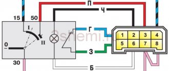
| Failure of the relay regulator | The relay is responsible for the battery, preventing the generator from recharging it. Failure of the relay-regulator leads to a complete lack of charge. In this case, diagnostics is required. |
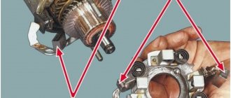
| Brush wear | The graphite brushes moving along the generator stator tracks wear out quite often. They need to be changed periodically. |
| Winding burnout | The winding on the rotor or stator may burn out as a result of overloading the device. It can also short out when exposed to moisture. |
| Bearing jamming | During the operation of the car, the alternator bearings wear out, as a result of which the generator begins to jam. This leads to a rupture of the belt and, as a result, to failure of the generator. |
Some faults are difficult to notice, so drivers come to the service center with a generator that is no longer working and a “tired” battery. Therefore, it is important to periodically diagnose the generator using a multimeter.
How to test a generator with a multimeter
What elements does the stator of a synchronous generator consist of and the principle of operation?
- Package of stator windings;
- Stator core or package;
- Wires for connection output.
The stator itself is made of three windings, three different current values are formed in them, this circuit is a three-phase output. The ends of each winding extend from the generator body (they are connected to it), the second end is connected to the rectifier. To concentrate and enhance the magnetic field in the generator, a core made of metal plates is used.
The stator winding of a synchronous generator is located in special slots, usually there are 36 such slots. In each slot, the winding is held by a wedge. This wedge is made of insulating materials.
Checking the generator without removing it
Step 1: Set the parking brake and raise the hood.
Lift the hood
Step 2 . Connect the multimeter to the battery terminals (do not mix up the “+” and “-” terminals). Place the device itself on the battery, as in the photo. When the car is not running, the battery charge should be about 12.5-12.6 V.
Connect the multimeter to the battery
Step 3: Start the engine.
Start the vehicle
Step 4: Monitor your metrics. 1-2 seconds after startup, the voltage should increase to 14.3-14.4 V.
Monitor your multimeter readings
Step 5. Give maximum load to the generator. To do this, you need to turn on all the car's consumers: lights, heater, heated windows and mirrors.
Turn on the light
Turn on the stove
Turn on the heated seats
Step 6. Monitor the battery voltage. If the indicators have changed slightly (14.1-14.2 V), then this indicates normal operation of the generator. If the voltage drops significantly when the devices are turned on (to 13-13.5 V), then diagnostics of the generator is needed.
Monitor the voltage coming from the generator
Voltage Regulator Diagnostics
To check the voltage regulator on a VAZ 2114, 2106 car, you should perform the following steps:
- Start and warm up the engine by turning on the headlights. Warm up the engine for about 15 minutes. For diagnostics, a multimeter or voltmeter capable of taking measurements in the voltage range 0-15 V is used.
- Measure the voltage between ground and terminal 30. For most cars in normal condition, the reading will be within 13.5-14.6 V. A value less than 13 V means the unit needs to be replaced.
Check with removal
No preparations or preparatory steps are required for testing. You just need to remove the generator itself and prepare a multimeter. A full check of the device consists of diagnostics of the relay regulator, diode bridge, stator and rotor windings. Let's consider the procedure for checking each of these elements separately.
Checking the generator with a multimeter and removing
Checking the relay regulator
Step 1. Remove the relay regulator and prepare a multimeter.
Remove the relay regulator
Step 2. Prepare a light bulb with two wires (as in the photo).
Connect a light bulb with two wires
Step 3. Connect the wires from the light bulb to the brushes ( See Replacing generator brushes ) of the relay regulator.
Connect the wires to the brushes
Step 4. Now you need to connect an regulated power supply to the “+” and “-” relays.
You need to connect the power supply to the plus and minus
Step 5. Connect the negative of the power supply to the negative of the relay. Secure the wire using a metal crocodile clip.
Connect the minus of the power supply to the relay
Step 6. Connect the second terminal of the power supply in the same way.
Now connect the plus
Step 7. The finished design should look like this.
This is what the design looks like
Step 8. Now connect the multimeter to the terminals of the relay regulator. Everything is the same: “minus” to “minus”.
Connect the negative of the multimeter to the relay regulator
Step 9. Connect “Plus” to “Plus”.
Connect the positive terminal of the multimeter
Step 10: Turn on the power supply to supply voltage to the relay. The multimeter shows 3.8 V after switching on.
Turn on the power supply
Step 11. Gradually increase the voltage, look at the light bulb and the meter readings. The brightness of the light bulb gradually increases.
Slowly increase the voltage on the power supply
Step 12. At around 14 V, the light should go out suddenly. If this happens, then the relay regulator is working properly. Otherwise, replacement of this element is required. At this point, testing the relay-regulator under load can be considered complete.
When the voltage increases to 14 V, the lamp should go out
Checking the diode bridge
Step 1. To work, prepare a multimeter with a ringing function and a diode bridge, which must be removed from the generator in advance.
Prepare the diode bridge and multimeter
Step 2: Check the first diode. It has positive polarity. The resistance of a working diode when tested in one direction should be from 400 to 700 Ohms.
Check the first diode with positive polarity
Step 3. In the other direction the resistance should be infinity. If this is the case, then the diode is fully operational.
Test the diode in the other direction
Step 4. Test the second negative diode in the same way.
Check the second negative diode
On a note! The resistance of the diodes can vary within certain limits and depend on the ambient temperature. When heated, the resistance decreases, and when cooled, it increases.
Step 5. Using this diagram, check all the remaining diodes. A burnt-out diode will have a resistance of infinity.
Repeat the procedure for the remaining diodes
Step 6. Small diodes are tested in the same way as large ones. The resistance of these diodes will be slightly lower than that of larger ones. A slight difference in the resistance of these diodes is considered normal. This completes the check of the generator diode bridge.
Check the small diodes on the bridge in the same way
Stator check
Step 1. Prepare the generator winding for testing. It is advisable to do this in a well-lit place.
Prepare the stator for diagnostics
Step 2. Take a multimeter and set it to test.
Set the ringing mode on the multimeter
Step 3. The winding has three outputs and they should all “ring” with each other.
The winding outputs should be directed upwards for convenience
Step 4. Connect the first terminal of the multimeter to one output, and touch the second terminal to the other two outputs in turn.
Connect the multimeter terminal to the winding output
Step 5. Check the stator for any holes in the metal. To do this, press the multimeter terminal to the edge of the winding, and the second one to the second edge.
Check the stator for metal damage
Step 6. Connect the second probe in turn to the winding outputs. If there are no signals, then the winding is intact.
Connect the terminal to the winding outputs one by one
Rotor check
Step 1. Prepare the generator rotor for further diagnostics.
Prepare the rotor for diagnostics
Step 2. Take a multimeter and set it to dial mode. The black probe should be in its original place, and the red one should be for measuring voltage.
Set the dialing mode on the multimeter
Step 3. Check the device for serviceability by connecting the black and red probes.
Connect the probes of the device to check its functionality
Step 4. Attach one feeler gauge to one rotor ring and the other to the other. In this way you can check for a break.
Attach the probes to the rotor rings
Step 5. Check the rotor for breakdown. To do this, one probe must be pressed against the ring, and the second against the body. If there is no breakdown, then the multimeter shows infinity.
Check the rotor for breakdowns
Step 6. Set the multimeter to resistance measurement mode in the 200 ohm range.
Set the resistance measurement mode on the multimeter
Step 7. Place one feeler gauge on one rotor ring, and the second on the other (as done previously). If the winding is intact, then the resistance should be around 3 ohms.
Reattach the probes to the rotor rings
Symptoms of malfunction
may indicate a generator malfunction :
- the warning light on the dashboard is constantly on;
- The battery began to discharge quickly, and recharging does not save the situation;
- there are malfunctions in the functioning of electrical equipment (ventilation and heating, multimedia devices, alarm system and lighting), even if the motor is working properly;
- there was a smell of something burnt in the car interior;
- the generator began to whistle or rustle.
If you notice these symptoms, you should immediately go to a car service center for a thorough diagnosis. However, you can check the functionality of the generator on your own, especially if you have the skills to use an autotester.
Additional recommendations
Before starting the test, you need to familiarize yourself with the type of generator set, because the relay regulator can support different values depending on the car model. We are talking about the range from 13.6 to 14.2 V. All these subtleties need to be learned before starting the test, because the final result may depend on them.
Checking the car generator
Otherwise, the process of checking the generator is simple, so even without experience, the driver can do it on his own. Of course, you need to start by checking the generator without removing it. Only by its results can you determine whether the device needs to be dismantled or not. Also, during the test, you can identify other faults related to the generator or other electrical devices of the car.
Generator diagnostics will help prevent serious malfunctions
