The correctness and stability of the operation of all vehicle electronics depends on the serviceability of the generator, because it powers all devices after the engine starts. Therefore, it is important to maintain the generator in “combat” condition, which means servicing it correctly. Periodically checking the generator with a multimeter will identify possible malfunctions of the device and increase its service life. More details on how to check a car generator with a multimeter (with and without removing the device) will be discussed in this article.
Multimeter - what is it
A multimeter is a measuring device used to measure resistance, current or voltage. Also, using such a device you can check the wiring for breaks. Each of these measurements involves the use of separate measuring instruments, such as a voltmeter, ammeter or ohmmeter. Therefore, a multimeter is considered a universal tool (mulmeter = voltmeter + ammeter + ohmmeter). In practice, analog and digital multimeters are used.
What is a multimeter
Analog
This multimeter is equipped with a special hand, like on a watch, by the movement of which the measurements are read. The analog multimeter is also equipped with a measuring scale with resistance, current and voltage values. The device is inexpensive, so it is very popular. The disadvantages of an analog multimeter include measurement errors (this mainly applies to products made in China).
Analog multimeter
Digital
Unlike an analog multimeter, a digital multimeter has an LCD or LED screen that displays data. These devices are easier to use and also have high accuracy, which cannot be said about cheaper analogues.
Digital multimeter
Note! Some types of digital multimeters can work in conjunction with a computer, transferring data obtained as a result of measurements to it.
Video - How to use a multimeter
First stage
To check the generator stator winding, use the ohmmeter indicated above. Measure the resistance of the generator field winding. Measurement results should be between 5 and 10 ohms. If the results are different, then there may be a break in the winding.
Now you need to check the insulation resistance of the generator. To do this, connect one of the ohmmeter probes to one of the stator contact rings, and touch the stator housing with the other probe.
The measurement result should be infinite resistance. If not, then the winding is “broken” and shorts to the housing (ground).
After the stator, it is necessary to check the generator rotor using the same method.
Possible generator breakdowns
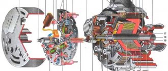
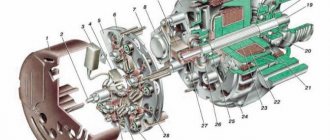
All generator malfunctions can be divided into two types - mechanical and electrical. Mechanical breakdowns can be identified by visual inspection of the device (cracks in the housing, wear of the tension roller or belt, delamination, etc.). To identify electrical faults, special tools are needed.
Common generator problems
Table. Damage to the electrical part of the generator.
| Malfunction, photo | Description |
| Failure of the relay regulator | The relay is responsible for the battery, preventing the generator from recharging it. Failure of the relay-regulator leads to a complete lack of charge. In this case, diagnostics is required. |
| Brush wear | The graphite brushes moving along the generator stator tracks wear out quite often. They need to be changed periodically. |
| Winding burnout | The winding on the rotor or stator may burn out as a result of overloading the device. It can also short out when exposed to moisture. |
| Bearing jamming | During the operation of the car, the alternator bearings wear out, as a result of which the generator begins to jam. This leads to a rupture of the belt and, as a result, to failure of the generator. |
Some faults are difficult to notice, so drivers come to the service center with a generator that is no longer working and a “tired” battery. Therefore, it is important to periodically diagnose the generator using a multimeter.
How to test a generator with a multimeter
How to check the operation of a generator in a car without measuring instruments
The functionality of the generator can be checked without a multimeter or tester by removing the minus terminal while the engine is running. This method is only suitable for older car models where the power circuit is not controlled by the ECM (Electronic Engine Control System). If you use this method on modern internal combustion engines, then as a result of a sharp surge in voltage, part of the electrical equipment may fail, the fuses in the unit may blow, the adjustment of many sensors may be disrupted, and the system will display a “Check Engine” error.
On old-type units, the check is performed as follows:
- Start the engine at idle speed.
- Remove the negative terminal from the battery during operation.
- If the generator is faulty, the engine stops spontaneously.
- If the unit is working, then you should add speed and make sure that the generator is working properly by turning on current consumers (headlights, air conditioning).
During the process, pay attention to the drop in speed when the terminal is removed: installing it in place should significantly increase torque without opening the throttle.
Important! Touching the battery power cables with bare hands is strictly prohibited. The terminal must be removed using insulating gloves, carefully moving it to the side.
Checking the generator without removing it
Step 1: Set the parking brake and raise the hood.
Lift the hood
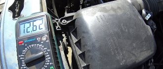
Step 2 . Connect the multimeter to the battery terminals (do not mix up the “+” and “-” terminals). Place the device itself on the battery, as in the photo. When the car is not running, the battery charge should be about 12.5-12.6 V.
Connect the multimeter to the battery
Step 3: Start the engine.
Start the vehicle
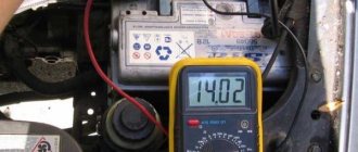
Step 4: Monitor your metrics. 1-2 seconds after startup, the voltage should increase to 14.3-14.4 V.
Monitor your multimeter readings
Step 5. Give maximum load to the generator. To do this, you need to turn on all the car's consumers: lights, heater, heated windows and mirrors.
Turn on the light
Turn on the stove
Turn on the heated seats
Step 6. Monitor the battery voltage. If the indicators have changed slightly (14.1-14.2 V), then this indicates normal operation of the generator. If the voltage drops significantly when the devices are turned on (to 13-13.5 V), then diagnostics of the generator is needed.
Monitor the voltage coming from the generator
Testing for functionality without a car using a battery and a light bulb
During the operation of a car, there are situations when it is necessary to purchase individual components and assemblies. For example, when purchasing a used generator, sometimes it becomes necessary to check the operating condition of the device without the car.
The functionality of the unit removed from the vehicle can be easily checked. To do this you will need a 12 Volt battery, a 3 Volt light bulb with two wires attached that easily lights up when exposed to voltage, two separate wires.
The check itself is carried out in the following order:
Such a test allows you to determine the functionality of the generator. In addition, it is important to carefully inspect the unit visually. To do this, you need to remove the plastic cover by pressing the latches and prying it off with a screwdriver.
Here attention should be paid to the integrity of the diode bridges, the absence of melted points, the integrity of the armature, and the absence of severe pronounced wear. In addition, you need to check the serviceability of the bearings when the shaft rotates. They shouldn't make noise.
And one more similar method. You will also need a battery for testing. But as an indicator, you can use a regular 12-volt light bulb from a turn signal.
The procedure is carried out in the following order:
If the generator is working properly, the control light should light up.
Every responsible motorist must monitor the operation of his car’s charging system. This should simply be included in the list of useful driver habits. The methods described above demonstrate high efficiency, accuracy and reliability against the backdrop of accessibility and simplicity. Therefore, it is better to take them into service.
Source
Check with removal
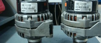
No preparations or preparatory steps are required for testing. You just need to remove the generator itself and prepare a multimeter. A full check of the device consists of diagnostics of the relay regulator, diode bridge, stator and rotor windings. Let's consider the procedure for checking each of these elements separately.
Checking the generator with a multimeter and removing
Checking the relay regulator
Step 1. Remove the relay regulator and prepare a multimeter.
Remove the relay regulator
Step 2. Prepare a light bulb with two wires (as in the photo).
Connect a light bulb with two wires
Step 3. Connect the wires from the light bulb to the brushes ( See Replacing generator brushes ) of the relay regulator.
Connect the wires to the brushes
Step 4. Now you need to connect an regulated power supply to the “+” and “-” relays.
You need to connect the power supply to the plus and minus
Step 5. Connect the negative of the power supply to the negative of the relay. Secure the wire using a metal crocodile clip.
Connect the minus of the power supply to the relay
Step 6. Connect the second terminal of the power supply in the same way.
Now connect the plus
Step 7. The finished design should look like this.
This is what the design looks like
Step 8. Now connect the multimeter to the terminals of the relay regulator. Everything is the same: “minus” to “minus”.
Connect the negative of the multimeter to the relay regulator
Step 9. Connect “Plus” to “Plus”.
Connect the positive terminal of the multimeter
Step 10: Turn on the power supply to supply voltage to the relay. The multimeter shows 3.8 V after switching on.
Turn on the power supply
Step 11. Gradually increase the voltage, look at the light bulb and the meter readings. The brightness of the light bulb gradually increases.
Slowly increase the voltage on the power supply
Step 12. At around 14 V, the light should go out suddenly. If this happens, then the relay regulator is working properly. Otherwise, replacement of this element is required. At this point, testing the relay-regulator under load can be considered complete.
When the voltage increases to 14 V, the lamp should go out
Checking the diode bridge
Step 1. To work, prepare a multimeter with a ringing function and a diode bridge, which must be removed from the generator in advance.
Prepare the diode bridge and multimeter
Step 2: Check the first diode. It has positive polarity. The resistance of a working diode when tested in one direction should be from 400 to 700 Ohms.
Check the first diode with positive polarity
Step 3. In the other direction the resistance should be infinity. If this is the case, then the diode is fully operational.
Test the diode in the other direction
Step 4. Test the second negative diode in the same way.
Check the second negative diode
On a note! The resistance of the diodes can vary within certain limits and depend on the ambient temperature. When heated, the resistance decreases, and when cooled, it increases.
Step 5. Using this diagram, check all the remaining diodes. A burnt-out diode will have a resistance of infinity.
Repeat the procedure for the remaining diodes
Step 6. Small diodes are tested in the same way as large ones. The resistance of these diodes will be slightly lower than that of larger ones. A slight difference in the resistance of these diodes is considered normal. This completes the check of the generator diode bridge.
Check the small diodes on the bridge in the same way
Stator check
Step 1. Prepare the generator winding for testing. It is advisable to do this in a well-lit place.
Prepare the stator for diagnostics
Step 2. Take a multimeter and set it to test.
Set the ringing mode on the multimeter
Step 3. The winding has three outputs and they should all “ring” with each other.
The winding outputs should be directed upwards for convenience
Step 4. Connect the first terminal of the multimeter to one output, and touch the second terminal to the other two outputs in turn.
Connect the multimeter terminal to the winding output
Step 5. Check the stator for any holes in the metal. To do this, press the multimeter terminal to the edge of the winding, and the second one to the second edge.
Check the stator for metal damage
Step 6. Connect the second probe in turn to the winding outputs. If there are no signals, then the winding is intact.
Connect the terminal to the winding outputs one by one
Rotor check
Step 1. Prepare the generator rotor for further diagnostics.
Prepare the rotor for diagnostics
Step 2. Take a multimeter and set it to dial mode. The black probe should be in its original place, and the red one should be for measuring voltage.
Set the dialing mode on the multimeter
Step 3. Check the device for serviceability by connecting the black and red probes.
Connect the probes of the device to check its functionality
Step 4. Attach one feeler gauge to one rotor ring and the other to the other. In this way you can check for a break.
Attach the probes to the rotor rings
Step 5. Check the rotor for breakdown. To do this, one probe must be pressed against the ring, and the second against the body. If there is no breakdown, then the multimeter shows infinity.
Check the rotor for breakdowns
Step 6. Set the multimeter to resistance measurement mode in the 200 ohm range.
Set the resistance measurement mode on the multimeter
Step 7. Place one feeler gauge on one rotor ring, and the second on the other (as done previously). If the winding is intact, then the resistance should be around 3 ohms.
Reattach the probes to the rotor rings
How to check the serviceability of a car generator without removing it (without dismantling)
A quick on-site check of the generator is carried out using a 12-volt light bulb and a tester. This method provides data on the correctness of the voltage readings in a parallel connection of the circuit with the battery.
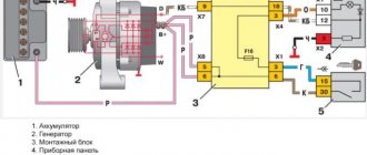
Scheme of checking with a light bulb and a tester
Procedure:
- Connect the lamp into the circuit using regular wires between the generator terminal B+ and the positive terminal of the rotor D+.
- Connect the minus terminal on the battery and the minus contact of the generator with power wires (fasten to ground).
- The positive terminal of the battery is also connected to the positive terminal B+ using a power cable.
- The tester is connected respectively to the battery contacts and the DC (voltmeter) mode is turned on. The voltage reading here should be 12.4 - 12.8 Volts. This indicates the serviceability of the circuit and the state of charge of the battery.
- Next, the generator drive must be cranked manually without starting the engine. To do this, remove the belt drive from the pulley and use a drill or screwdriver: select the appropriate adapter head for the centering nut on the pulley.
- At low speeds, the voltage on the tester will be 14–14.9 Volts, and the control light should go out.
- Then wait 1-2 minutes and measure the voltage in passive mode again. The value should return to 12.4–12.8 Volts.
Attention! When connecting a circuit, the ground wires are always connected last to avoid a short circuit to the battery.
This testing method gives the general state of the generator’s performance without identifying possible violations in the winding elements, relays, brushes and diodes. For a complete diagnosis, use a multimeter, testing each section separately in various modes.
Additional recommendations
Before starting the test, you need to familiarize yourself with the type of generator set, because the relay regulator can support different values depending on the car model. We are talking about the range from 13.6 to 14.2 V. All these subtleties need to be learned before starting the test, because the final result may depend on them.
Checking the car generator
Otherwise, the process of checking the generator is simple, so even without experience, the driver can do it on his own. Of course, you need to start by checking the generator without removing it. Only by its results can you determine whether the device needs to be dismantled or not. Also, during the test, you can identify other faults related to the generator or other electrical devices of the car.
Generator diagnostics will help prevent serious malfunctions
When is the inspection carried out?
Typically, this check is carried out before repairing the generator in order to find out what is the cause of the breakdown, and already know in advance how much it will cost.
The advantage here is obvious, since you will not deceive yourself, and after checking the car’s generator, you will receive reliable information.
In order to check the car's generator, get a special ohmmeter that supports diode testing and the ability to measure high resistances.
Checking a car generator can be divided into four main stages.
Checking the generator stator winding, checking the generator diode bridge, checking the voltage regulator, checking the generator capacitors.
Good to know - Replacing the VAZ 2110 generator bearing, do it yourself, video, photo.
Synchronous alternators
Synchronous generators operate in a similar way, but the shaft speed is maintained at a constant speed. Hence the parameters are more stable. Here are a number of differences that need to be taken into account in order to properly test the generator with a multimeter.
AC winding
The stator (called the armature) often has an alternating current winding that synchronizes the rotation. Its role is difficult to overestimate, and the turns are located, for example, between the windings of the main coil. The role of the poles in this case is synchronizing. A voltage of the required frequency is supplied here, which, through interaction with the inductor (rotor), sets the speed of rotation. Typically the winding dimensions are smaller than the main winding and the resistance is higher.
Subexciter
Large synchronous generators contain auxiliary equipment - a subexciter. This is a synchronous machine whose shaft is equipped with permanent magnets. The voltage generated by the generator is rectified and is subsequently used as current for the exciter. This saves energy. Permanent magnets also reduce the number of current collectors, which has a positive effect on the reliability of the entire system. The subexciter becomes, in fact, a simple synchronous motor; the stator winding is tested by the tester in the usual manner.
Diode bridge
In connection with the above, sometimes it is necessary to check the diode bridge of the generator with a multimeter. By the way, this is relevant for car enthusiasts, where a Larionov circuit is often used to rectify the current. The diode bridge is called depending on the design. In everyday life, the ones shown in the figure are the most common. The first is considered a typical solution for single-phase alternating current, and the second is the Larionov circuit.
According to the given figure we show how to ring. A single-phase diode bridge is safely assessed for the integrity of each diode individually. To do this, the appropriate mode is set on the multimeter, then, regardless of the position of the cathode and anode, the probes are presented on one side, then on the other. As a result, direct connection produces a value of 500 - 700 Ohms, and reverse connection produces a break.
Popular designs of diode bridges
The result is different if the bridge is shorted by resistors somewhere in the circuit, but this rarely happens, and their value is large enough to have no effect. The Larionov automobile bridge is called similarly. If possible, remove it from under the hood. The input of each phase is connected to the positive and negative output. Resistance value – up to 1 kOhm. The reverse connection is easy to check. It is necessary to put the red probe on the plus side and, in turn, make sure that all phases give an infinitely large resistance to the black probe. The mass is checked in the same way. Here the black probe goes along the negative output, and the red one goes through the phases.
Let's move on to the second stage
Checking the diode bridge.
We switch the ohmmeter to the mode in which diodes are checked. We connect the positive contact of the ohmmeter to the central (common) diode bus. We connect the negative terminal to the terminal of the diode that you are testing. If the resistance is infinite or tends to infinity, then the diode is working; if the device shows other parameters, then the diode is faulty.
The next step is to reverse the positions of the ohmmeter terminals. Resistance readings should be close to zero, but not zero.
So it is necessary to check each diode in order to get an accurate result of checking the diode bridge.
Now you need to check whether the diode is breaking through to the ground of the car. To do this, we connect the positive terminal of the ohmmeter to the plate in which the diodes are located, and the negative terminal, as in the previous case, to the terminal of the diode.
If the resistance tends to zero, then the diode is faulty, and if it approaches infinity, then it is faulty.
I would like to add that if you have identified at least one faulty diode, then replace the entire diode bridge, it will be more reliable.
The next step is checking the car generator.
Main signs of generator malfunction
The following signs will indicate that the generator has failed or problems have arisen in its operation:
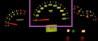
- constant lighting of the warning light in the form of a reddish battery on the dashboard, which indicates that the generator is not charging or is producing insufficient current;
- constantly discharging battery;
- interruptions in the operation of electrical equipment (lighting and alarm units, multimedia, heating and ventilation) while the engine is running;
- the appearance of a corresponding burnt aroma in the cabin (engine department);
- excess heating of the generator stator;
- rumble (rustle, whistle) of the generator.
Read also: Threaded inserts for thread restoration
The appearance of similar symptoms is a serious reason to conduct a diagnosis. To do this, it is absolutely not necessary to contact a service station, because you can completely check the generator for operability on your own, especially if you have even the slightest ability to use an auto tester. But first, let's talk about the main breakdowns.
Recharging the battery
The generator does not always undercharge the battery; it happens quite often when overcharging occurs, that is, the generator unit produces voltage above the prescribed norm. As a rule, the cause of overcharging is a faulty voltage regulator; it does not work as expected, and the generator continues to produce current when the battery is fully charged.
Without removing the generator from the car, the relay-regulator is checked in the same way as with undercharging, only in this case the multimeter shows the voltage of the on-board network when the load is on more than 14.7 V (readings can be even higher, for example, even more than 17 Volts) . Constant overcharging is dangerous because it:
- the electrolyte in the battery banks begins to boil;
- lead plates of the battery are exposed;
- sulfation occurs (destruction of the plates), the battery becomes inoperable;
- Due to increased voltage, light bulbs may burn out, electrical equipment may fail, and fuses may burn.
There is still a danger of a battery explosion, which occurs due to clogging of the holes in the plugs of the battery cans when the electrolyte is boiling.
On many VAZ cars of the “Classic” family (in particular, on the VAZ-2106), the voltage relay can be changed quite easily, as it is located separately, located next to the front fender of the car. The relay-regulator of the VAZ-2105 and 2107 type is located in the generator itself, it is a little more difficult to get to, but replacing it is also easy.
There are two power sources in a car - a battery and a generator. The first powers the electrical circuit when the engine is not running. The second is when the engine is already running. In this case, the battery goes into electric current consumer mode and replenishes the energy expended to start the engine.
In practice, malfunctions of one or another power supply are quite common. They often manifest themselves in the same way. The starter refuses to spin the engine, and as a result the engine does not start. When the engine is running, the warning light on the instrument panel with the battery icon lights up. It indicates that a malfunction has occurred and the battery is not charging.
Checking the voltage regulator
This is a little difficult for a non-technically unprepared driver, but still many people use this method and, at the same time, successfully.
The first thing to do is inspect the brushes. They should protrude from the holder no more than 5 millimeters. The brushes must move freely in the holder, they must be intact and not worn out.
Now comes the fun part. Here you will need a current source with which you can change the output voltage using a regulator and a control light.
We connect the positive terminal to the terminal of the device, and the negative terminal to the ground of the voltage regulator. We connect the control to the brushes.
We supply 13V to the voltage regulator, and the control should light up. After you increase the voltage to 14.5-15 Volts, the control lamp should go out because the regulator has stopped supplying voltage to the brushes. This is fine. By reducing the voltage to 13 volts, the lamp should light up again.
It is important to read: Why the battery does not charge, the reasons you need to know about.
Asynchronous alternating current generators
These generators are called asynchronous because the frequency of the generated current differs from the speed of rotation of the shaft (even taking into account the number of poles). Structurally, such a machine is considered a typical motor with a wound or magnetized rotor. Shaft winding differs from synchronous winding in the absence of a section between the poles. Due to this, the plus and minus are less pronounced. So, depending on the type of design of an asynchronous motor, the method of starting it in generator mode differs.
For a squirrel-cage rotor, it is necessary to pre-magnetize the shaft. This is done using a short but strong current pulse. The location of the poles depends on the polarity. Please note that the relatively small cross-section of the shaft will not allow creating a strong magnetic field. This means, in accordance with the above, we come to the conclusion that it will not be possible to obtain high voltage using the described generator. It is much more profitable to magnetize a phase rotor from plates by applying voltage to the coils. Voltage will begin to be removed from the stator. The driving force is:
- Burning gases or car engine shaft.
- Wind wheel.
- Bike.
Electricity is generated by changing the field. Magnets can be permanent (squirrel-cage rotor) or electric (wound rotor). The second type of device needs to be powered with current, for example, from a battery through a slip ring (ring on the shaft). In accordance with this design, methods for testing the multimeter generator emerge. In the case of a squirrel-cage rotor, we test exclusively the stator. The number of pins depends on the power phase and other features:
Asynchronous type generator
- The stator windings of a three-phase generator are connected in a star circuit. They form a common point, and the three opposite ends are placed on phases A, B and C. In this case, you should check the generator in pairs with a multimeter for the resistance value. The answer is always the same.
- Then the insulation on the body is checked. This will require special equipment: a 500 V test voltage driver and a current clamp (one option among others). The insulation resistance according to the standard is not less than 20 MOhm. If there is a short circuit, the motor is built according to a circuit with a solidly grounded neutral, which is typical for voltages up to 1 kV. In this case, the design is specified according to technical characteristics. It’s easier to find data on an asynchronous motor on the Internet.
- The stator of a household asynchronous motor is much more complex. Such machines are not used as generators, but... we will show you how to check their functionality. More often there are two windings, one is powered through a capacitor and becomes a starting or auxiliary one. In our case, it is permissible to relieve tension from each. The resistance of the auxiliary (or starting) winding is usually slightly greater than that of the working one. This is easy to check with a tester. Then the insulation resistance on the generator housing is measured.
The rotor is tested together with current collectors. Three-phase circuits are designed to work with an isolated neutral; to check the generator winding with a multimeter, you should measure the resistance between all three rings in pairs. The values must be equal. Sometimes there is a short circuit to the housing (circuit with a solidly grounded neutral). It all depends on the design features of the engines (generators). If there are one or two rings, we conclude that the power supply is single-phase. By calling the coil, we check the insulation on the body.
Alternator Auxiliaries
Alternators, like engines, are often equipped with thermal fuses, tachometers, Hall sensors and other auxiliary equipment. There are also specific stages, for example, a generator protection relay from asynchronous mode (which can lead to equipment failure). In general, keep in mind that ordinary engines are often started in a specific mode. Therefore, you need to be able to check the auxiliary equipment in the simplest possible way:
- Thermal fuses are designed for a certain temperature, usually indicated on the housing. When a certain threshold is exceeded, the insulation melts, which can lead to winding failure. If we take generators, they are protected from overload using overcurrent protection relays (overcurrent protection relays), which we consider to be analogous to fuses. The action is based on the power limit requested by the consumer. For example, if one phase short-circuits, it simply breaks off. As for thermal fuses in typical motors, their locations are usually limited to the surface of the magnetic circuit or the insulation of the windings (the bump is clearly visible among the turns). You should find the output terminals and test the circuit from the connector side.
- Thermal relays are considered analogues of thermal fuses with reusable operation, protecting the winding from combustion. When the engine has cooled down, current generation can be resumed.
- Frequency sensors are usually built on the principle of tachometers. The organization of devices varies, depending on which the check is carried out.
To summarize: each engine can be started in generator mode. This is written directly on Wikipedia. Be that as it may, the design of generators reveals peculiarities. Specific regulation and protection methods differ from those used for motors. The results of the shutdown impose restrictions: if the generator fails, the consequences are much more dire. Already due to the presence of such features, the price is very different.
In conclusion, we will say: according to anecdotal evidence, asynchronous generators have less vulnerability to short circuits on the load side, and the voltage shape is better. In addition, there is no need to maintain the shaft rotation speed, which will be a big plus for practitioners. As for the organization of hydroelectric power plants, they use exclusively synchronous machines due to the obviousness of the requirements of the standards.